

Elko eLAN-RF-003 Installation Manual
1/25
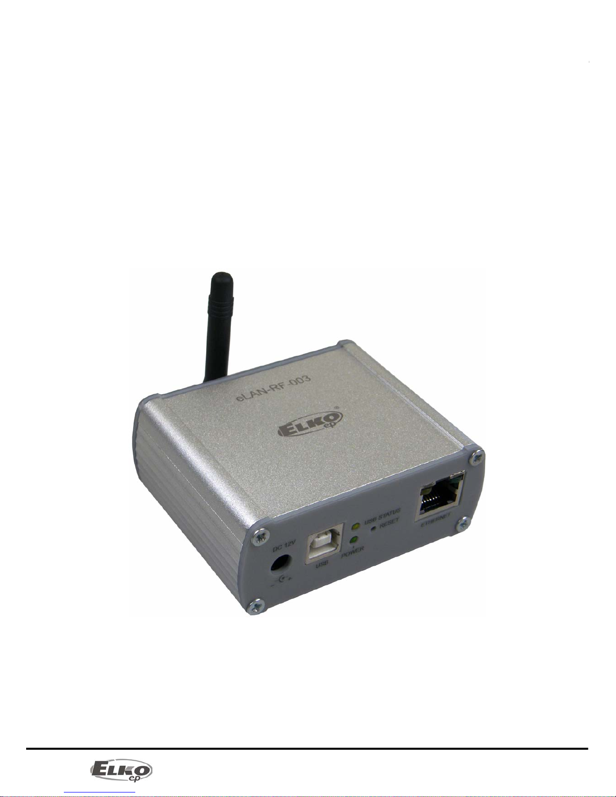
Converter Ethernet to RF signal
eLAN-RF-003
Introduction:
Installation Manual
02-040/2012
Instruction Manual for the
eLAN-RF-003

2/25
Converter Ethernet to RF signal
eLAN-RF-003
Introduction:
Installation Manual
02-040/2012
Contents
1. Introduction: ................................................................................................................................ 3
2. Main characteristics: .................................................................................................................... 3
3. Technical parameters: ................................................................................................................. 4
4. Hardware installation: ................................................................................................................. 5
4.1 Front panel: ........................................................................................................................... 5
4.2 Rear panel: ............................................................................................................................ 5
4.3 System requirements: ........................................................................................................... 6
4.4 Requirements for installation environment: ........................................................................ 6
4.5 Examples of use: ................................................................................................................... 6
5. Configuration of computer: ........................................................................................................ 8
6. Configuring the iMM Client: ...................................................................................................... 11
7. Configuration of the eLAN-RF-003: ........................................................................................... 12
8. Configuring the eLAN-RF-003 using the SW eLAN-RF-003 Configurator: ............................... 12
8.1 Administrator login: ............................................................................................................ 13
8.2 LAN parameters: ................................................................................................................. 13
8.3 About the device: ................................................................................................................ 13
8.4 Buttons: ............................................................................................................................... 13
8.5 Device settings: ................................................................................................................... 14
8.5.1 Basic settings. .............................................................................................................. 14
8.5.2 RF Repeater .................................................................................................................. 14
8.5.3 RF Router ..................................................................................................................... 16
8.5.4 List of addresses: .......................................................................................................... 18
8.5.5 User panel: ................................................................................................................... 19
9. Configuring the eLAN-RF-003: .................................................................................................. 20
9.1 Settings tab: ........................................................................................................................ 21
9.2 Tab Firmware: ...................................................................................................................... 22
9.3 Tab Builder: ......................................................................................................................... 23
9.4 Tab Panel: ............................................................................................................................ 24
9.5 Tab log out: ......................................................................................................................... 24
10. Troubleshooting: .................................................................................................................... 25

3/25
Converter Ethernet to RF signal
eLAN-RF-003
Introduction:
Installation Manual
02-040/2012
1. Introduction:
Congratulations on purchasing the eLAN-RF-003 control unit, an element of the RF Control wireless system.
Before you begin
The instruction manual provides information on installing and operating the device. The instruction manual is
always a part of the supply. Only per form installation after becoming thoroughly familiar with this User Guide
and device functions. Problem-free function of the device also depends on the way it was shipped, stored and
handled. If you notice any signs of damage, deformation, malfunction or a missing part, do not install this product
and return it to the point of sale. At the end of its service life, the product and its parts must be treated as electronic
waste. Before starting the installation, make sure that all wires and connected parts are not under voltage. When
assembling and performing maintenance, you must uphold safety regulations, standards, directives and special
provisions for working with electrical equipment.
2. Main characteristics:
The eLAN-RF-003 converter converts commands from the LAN TCP/IP network to an RF signal for
controlling RF actuators.
It enables bidirectional communication between the RF INELS and Ethernet systems.
It can be used to extend the range of the RF signal via UTP cable (Ethernet network) or WiFi (between
individual floors in the house).
Option of control and reading values from RF actuators (temperature, ON/OFF status) - in the iMM
environment.
Configuration and management of ELAN-RF-003 is performed via:
1) iMM server
2) its own web server
3) configuration SW eLAN-RF-003 Configurator
For access to eLAN-RF-003 from the Internet, you must connect the eLAN-RF-003 to a Public IP address.
The device is compliant with standards 802.3/802.3u (Fast Ethernet)
The device is compliant with standards ISO 802.3/ IEEE 802.3u ( 10BASE-T)
Automatic cable crossing detection of Ethernet cable - MDIX
10/100BaseT Ethernet, auto-detection
Option of powering by PoE – maximum voltage 27V / 200mA max. consumption.
Support for administration and configuration via web interface.
Supports firmware updates via a web interface.
It has its own web server
Aluminum design box in desktop style.

4/25
Converter Ethernet to RF signal
eLAN-RF-003
Technical parameters:
Installation Manual
02-040/2012
3. Technical parameters:
Interface RF Control
Communications protocol: Oasis & RF Touch Compatible
Transmitting frequency: 868 MHz
Signal transmission method bidirectionally addressed message
Output for antenna: SMA Connector
Indication of RF communication: 1 x red RF Status LED
Antenna: 1 dB (part of supply)
Range in open areas: up to 100m
Ethernet Communication
Operating status indication ETH: green LED
Communication indication ETH: yellow LED
Communications interface: 10/100 Mbps (RJ45)
Preset IP address: 192.168.1.1
Supply voltage / jm. Current: 10-27 V DC / 200 mA (safe low voltage)
Power supply PoE Max. 27V / 200mA max. consumption
Connection: connector Jack Ø 2.1 mm
Supply voltage indication: green LED
Other
Other powering options: connector USB-B
USB activity indication: yellow USB Status LED
Button RESET: restart product / reset product to factory settings
Power source: 230 VAC / 12 V DC part of supply
Working temperature: -20 .. +55 °C
Storage temperature: -25 .. +70 °C
Protection class: IP 20
Pollution degree: 2
Working position: any
Installation: free
Design: design box
Dimensions: 90 x 52 x 65 mm
Weight: 136 g
Factory settings:
Login: admin, user
Password: elkoep
IP address: 192.168.1.1
5/25
Converter Ethernet to RF signal
eLAN-RF-003
Hardware installation:
Installation Manual
02-040/2012
4. Hardware installation:
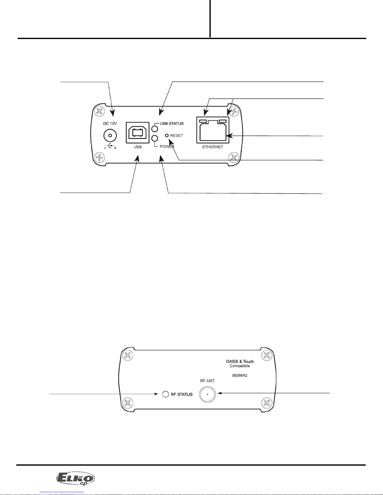
4.1 Front panel:
Power connector DC 12V – Input for connecting supplied power adapter.
Plug USB B – Used for servicing, (or can be used to power the product).
Green POWER LED power supply indicator.
Yellow USB Status LED – displays activity at the USB port.
Button RESET – used to restart or restore the product to factory settings*.
Connector Ethernet RJ 45 – used to connect mainly to the local network (LAN) or PC.
Yellow LED on Ethernet connector - indicates operating status.
Green LED diode on Ethernet connector - indicates communication.
*By shortly pressing (around 1s) the RESET button in the status where the product is connected to the supply
voltage, the product will restart. This restart neither changes nor deletes settings.
RESET to factory settings occurs after pressing and holding the RESET for min. 10s. This restart returns the product to
its factory settings, i.e. the IP adress is set to 192.168.1.1, the user name and password are set at: admin /
elkoep, user / elkoep, all learning and assigned IR codes and
the created web server control panel are erased.
4.2 Rear panel:
Red RF STATUS LED – Displays RF communication – during transmission the RF signal LED diode flashes.
SMA antenna connector – pro connecting the RF antenna.
Power connector
10-27V/200mA
Yellow USB status LED
LED indicator of Ethernet
communication
Ethernet connector (RJ 45)
RESET button
Green POWER LED power supply indicator
USB B connector
Red LED RF STATUS SMA antenna connector
6/25
Converter Ethernet to RF signal
eLAN-RF-003
Hardware installation:
Installation Manual
02-040/2012
4.3 System requirements:
Functioning iMM Client or PC with functioning Ethernet adapter.
For PCs, installed web browser (such as Mozilla Firefox,Opera, etc.).
You must have installed .NET Framework 3.5 and higher.
Connecting Ethernet cable with RJ45 connectors.
4.4 Requirements for installation environment:
The product cannot be placed where it is exposed to moisture or excessive heat.
Place the eLAN-RF-003 at a location where it can be connected to the Ethernet network, power source and
its RF antenna will be in sufficient distance from the controlled device.
For fault-free communication, adhere to the principles of installing the RF device, see RF catalog.
4.5 Examples of use:
Connect the power supply using the supplied adapter.
Connect the eLAN-RF-003 device to the Ethernet by a cable to the computer, iMM Client, eLAN-RF-003 or
Ethernet hub.(The cable must have an RJ45 connector, the device has an automatic cable crossover
detection function - so cable crossover does not present a problem).
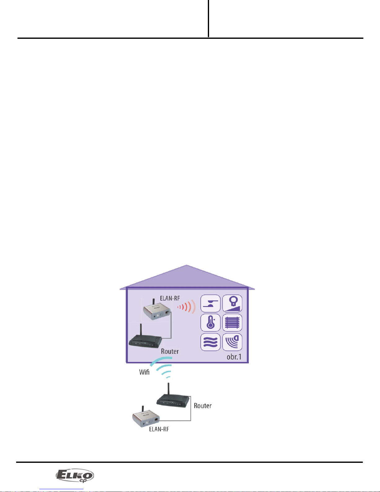
Example 1:
The example of use of two eLAN-RF-003 devices in connection with the WiFi network is advantageous when this
network is already in use, and is only augmented with the eLAN-RF-003 device. The eLAN-RF-003 device can
function if the WiFi routers are connected to a bridge and both eLAN-RF-003 devices can "see" each other. For this
case, it is necessary to set the eLAN-RF-003 to the routing function.
7/25
Converter Ethernet to RF signal
eLAN-RF-003
Hardware installation:
Installation Manual
02-040/2012
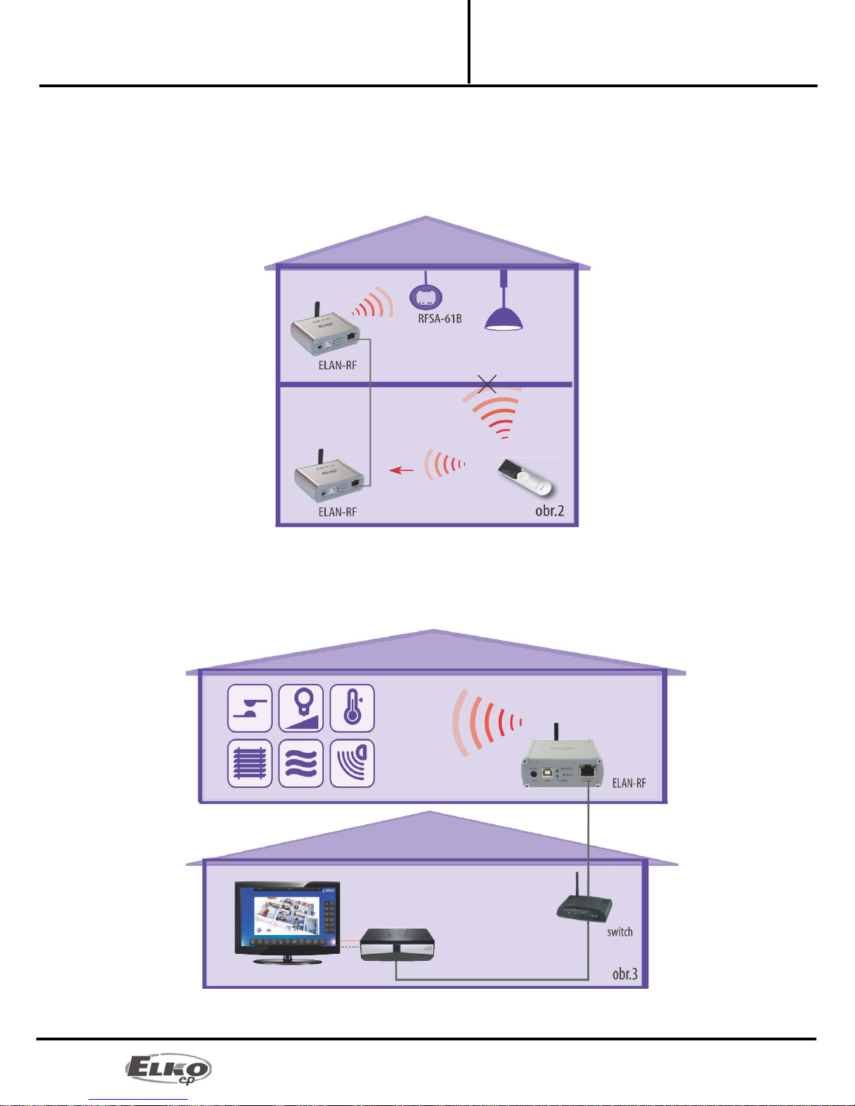
Example 2:
Basic use where the RF controller (RF Touch, RF Pilot, RFRF AP/USB, RF Key) cannot control the RF actuators, due to
great distance, and when it is not possible to use the RFRP-20 repeater. By simply connecting to the network or by
extending an Ethernet cable, you can extend the maximum range (distance) of RF controllers.
For this case, it is necessary to set the eLAN-RF-003 to the routing function.
Example 3:
The next example illustrates the case where you already own an iMM Client server and you want to control all the
RF actuators and maintain an overview on statuses of all RF actuators found within the range of the eLAN-RF-003.
8/25
Converter Ethernet to RF signal
eLAN-RF-003
Configuration of computer:
Installation Manual
02-040/2012
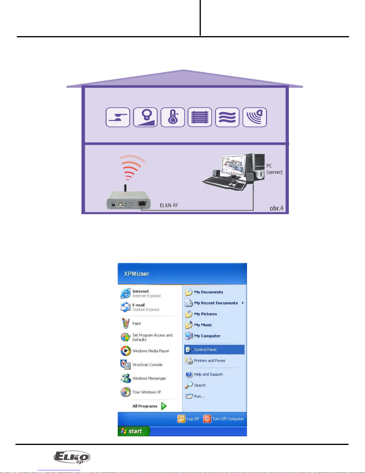
Example 4:
This example is similar to the previous one, except the device works via the PC. Thanks to the web server, it is easy to
control the RF actuators.
5. Configuration of computer:
For logging in to the web server or changing the IP address (192.168.1.1).
Example of configuration in the Windows system, proceed according to the following instructions:
1. In the computer Start menu, open the Control panel and select Network connections.
 Loading...