

Page 1
Page 2
Page 3
Instruktioner för antennförstärkare
ELKO Link Home R/TV Modul
Applikation
Förstärkaren används tillsammmans med ELKO
Link Home produkter. Förstärkaren är en grade 2
produkt och ej avsedd för kaskadkopplingar, den
inkluderar retursignaler för både kabelradio- och TVsignaler. Signalen från antenn för radio och TV
kopplas in på ingången och splittas ut på 6 parallella utgångar, varav 2 utgångar är med retursignal
(märkt Outputs sup. ret.path). Frekvensbanden på
förstärkarna för retursignalerna, se tabell.
AV-ingång; en extra port klarar ELKO Link Home
AV link, och är tillgänglig för AV-signaler (märkta ).
Signaler från ELKO Link Home modulatorer kopplade till den här porten mixas med antennsignalen
och distribueras till alla 6 utgångarna. Förstärkaren
klarar ELKO Link Home IR link system.
Konstruktion
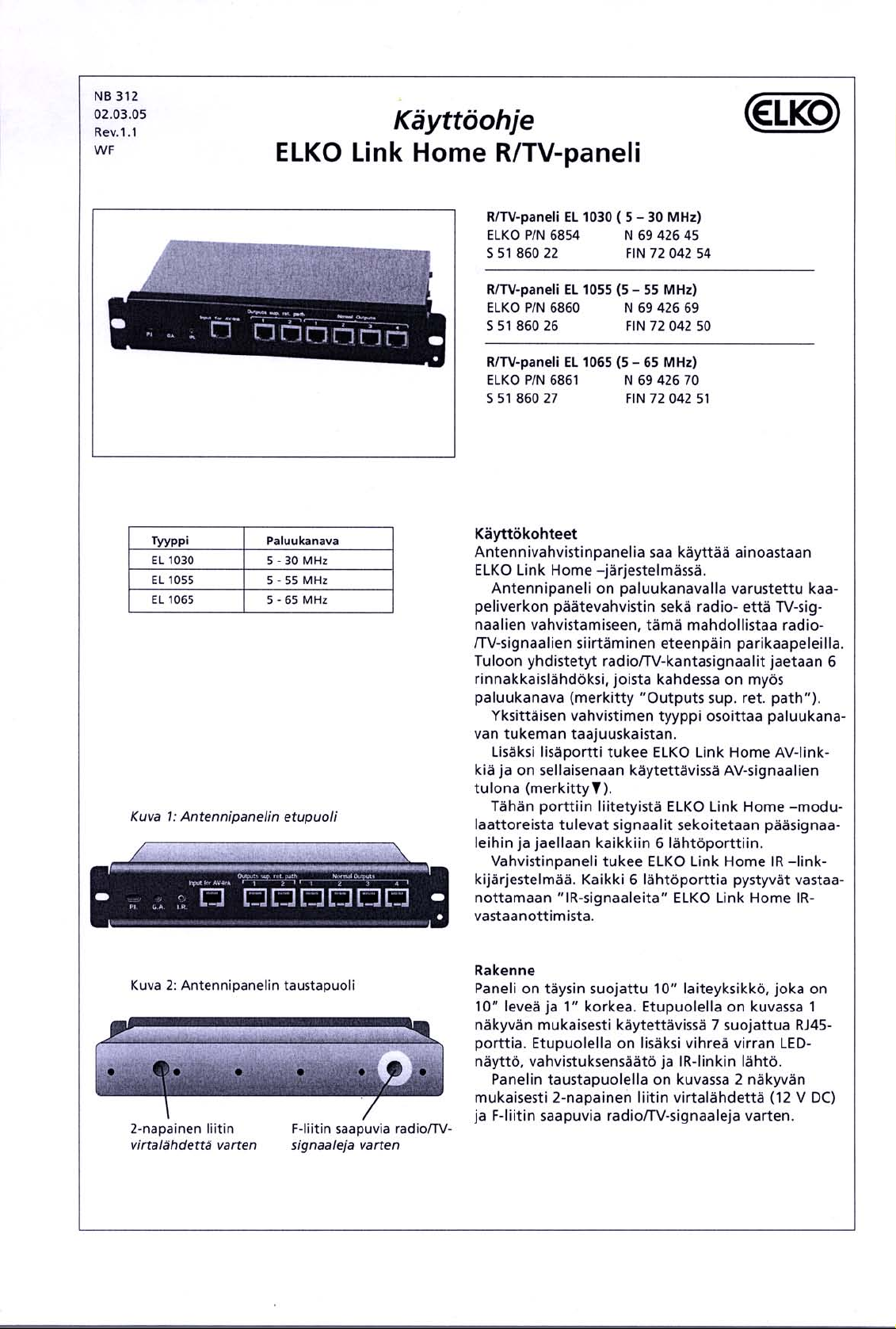
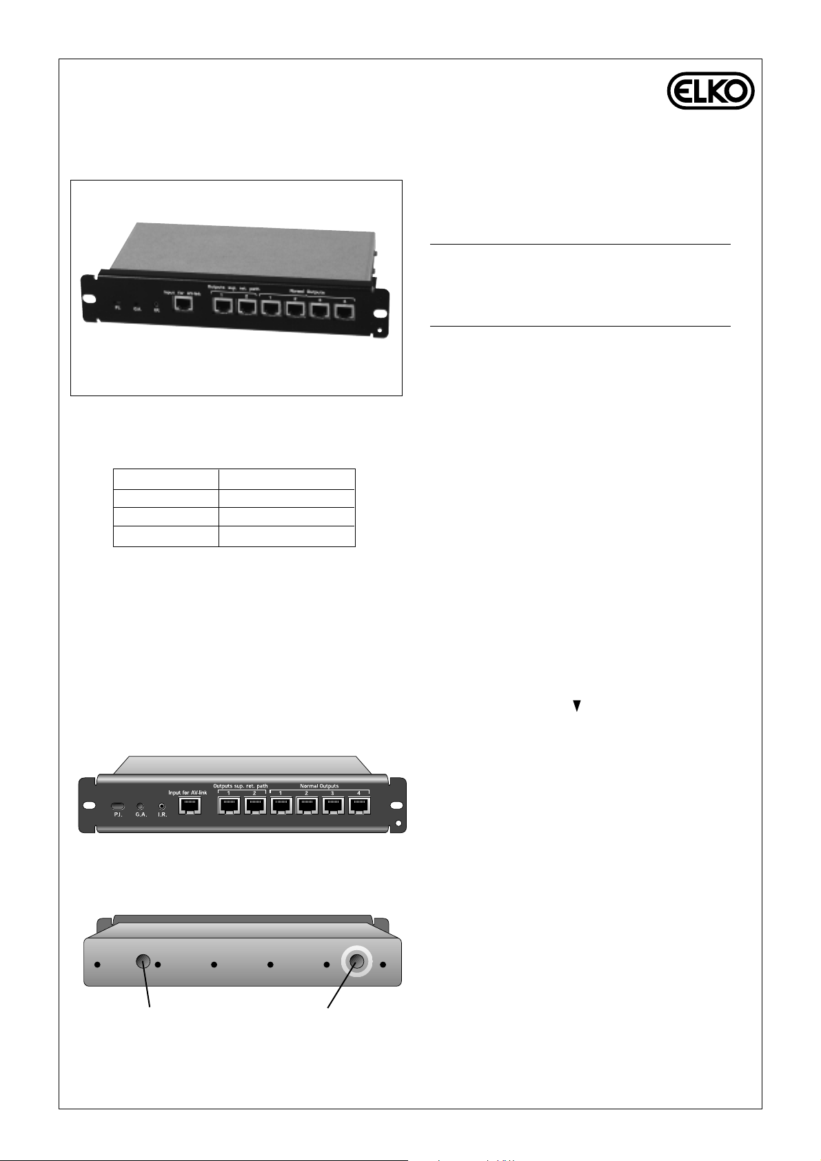
Förstärkaren är en fullt skärmad enhet i 10" utförande och 1HE. I fronten (se fig.1) finns 7 skärmade
RJ45 utgångar tillgängliga för användaren. En grön
LED indikator för på/av, en justerskruv för signalstyrkan samt ett utgående uttag för IR linken.
På baksidan av förstärkaren (se fig.2) finns en
tvåpolig kontakt för strömförsörjningen (12V DC)
samt en F-kontakt för inkommande radio- och TVsignal.
NB 312
02.03.05
Rev.1.1
WF
R/TV Modul EL 1030 (5-30 MHz)
ELKO P/N 6854 N 69 426 45
S 51 860 22 FIN 72 042 54
R/TV Modul EL 1055 (5-55 MHz)
ELKO P/N 6860 N 69 426 69
S 51 860 26 FIN 72 042 50
R/TV Modul EL 1065 (5-65 MHz)
ELKO P/N 6861 N 69 426 70
S 51 860 27 FIN 72 042 51
Typ
EL 1030
EL 1055
EL 1065
Retursignal
5 - 30 MHz
5 - 55 MHz
5 - 65 MHz
Fig 1: Antennförstärkaren sedd framifrån
Fig 2: Antennförstärkaren sedd bakifrån
2-polig kontakt för
strömförsörjning
F-kontakt för inkommande
radio- och TV-signal
Page 4
Gäller för samtliga:
Strömförsörjning
Strömförbrukning
Signaljustering
Dämpning
Ingångsimpedans
Utgångsimpedans
Ingångsnivå
Utgångsnivå
Antal TV kanaler
Störning
Isolering mellan utgångarna
Retursignaljustering
CTB
CSO
Stopp bands dämpning
AV link ingångsnivå
AV input frekvensområde
Arbetstemperatur
Standarder
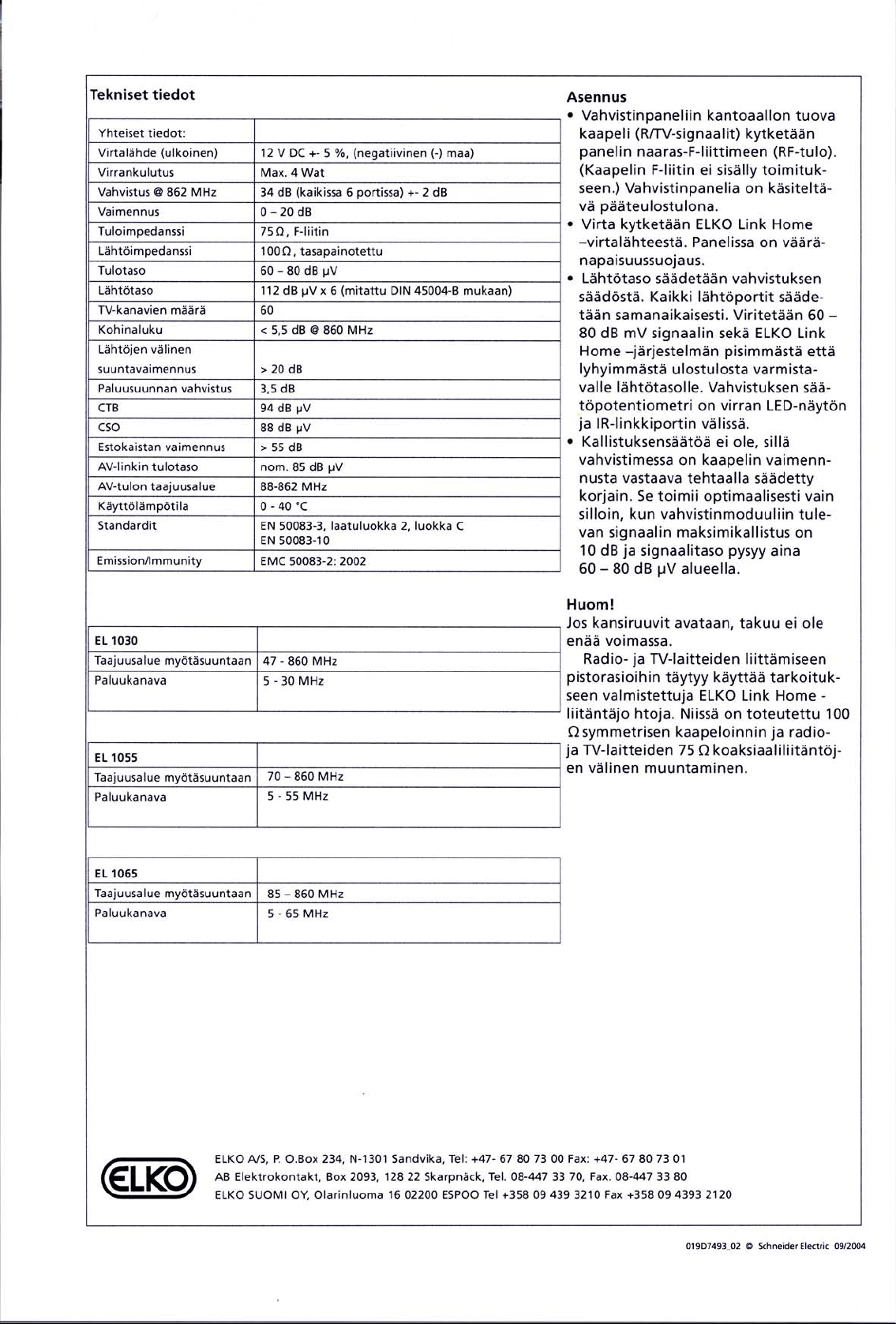
12 volt DC ± 5% , (Negative (-) put to GND)
3,5 Watt
35 dB (on all 6 ports) ± 2 dB
0 – 20 dB
75 Ohms , F-connector
100 Ohms , Balanced
60 – 80 dB µV
114 dB µV x 6 (Measured according to DIN 45004-B)
41
< 6.5 dB @ 860 MHz
> 20 dB
6 dB
94 dB µV
88 dB µV
> 55 dB
90 dB µV
88-470 MHz
0 - 40 °C
EN 50083-3 , quality grade 2 , cat. C
EL 1030
Frekvensområde, framåt
Retursignal
47 - 860 MHz
5 - 30 MHz
EL 1055
Frekvensområde, framåt
Retursignal
70 – 860 MHz
5 - 55 MHz
EL 1065
Frekvensområde, framåt
Retursignal
85 – 860 MHz
5 - 65 MHz
Tekniska specifikationer
Installation
• Kabeln för radio och TV signaler
kopplas in på F-kontakten (hona) RF
input på förstärkaren. (F-kontakt för
kabeln medföljer ej). Antennförstärkaren fungerar som ett slututtag.
• Strömmen kopplas från ELKO Link
Home nätadapter. Förstärkaren är
skyddad mot felaktig inkoppling av
polerna.
• Utsignal kan justeras med justerskruv, alla utgångar påverkas samtidigt. Signalen ska vara mellan 60 80 dB µV på både den längsta och
den kortaste installerade länken.
Justerskruven sitter mellan på/av
LEDoch IR link porten.
• Tiltsignalen behöver inte justeras
eftersom förstärkaren är anpassad
till ELKO Link Home kabeln
E49 370 83. Under förutsättning att
den inkommande signalen har ett
maximalt tiltvärde på 10 dB och
insignalen är mellan 60-80 dB µV.
Varning!
Om antennförstärkaren öppnas gäller
inte garantin.
När radio och TV ansluts till modularuttagen skall ELKO Link Home
anslutningskablage användas, i dessa
finns impedansanpassningarna mellan
ELKO Link Home 100 ohms nät och
radio och TV nätets 75 ohm.
ELKO A/S, P. O.Box 234, N-1301 Sandvika, Tel: +47- 67 80 73 00 Fax: +47- 67 80 73 01
AB Elektrokontakt, Box 2093, 128 22 Skarpnäck, Tel. 08-447 33 70, Fax. 08-447 33 80
ELKO SUOMI OY, Olarinluoma 16 02200 ESPOO Tel +358 09 439 3210 Fax +358 09 4393 2120
Page 5
User instructions
ELKO Link Home R/TV Module
Application
The amplifier module is to be used exclusively in
the ELKO Link Home system.
The module is a Quality Grade 2 product and is a
non-cascadeable amplifier, including return path,
used for both cable radio- and TV-signals. The main
radio-/TV-signals con-nected to the input are splitted
into 6 parallel outputs, where 2 of these also includes a return path (marked ”Outputs sup. ret. path”).
The frequency band supported by the return path
emerges from the type of the individual amplifier as
follows.
Further, an extra port is supporting the ELKO
Link Home AV link, and is as such available as input
for AV-signals (marked ).
Signals from ELKO Link Home modulators connected to this port are mixed with the main signals
and distributed to all 6 output ports.
The amplifier module is supporting the ELKO
Link Home IR link system. All 6 output ports are
able to receive “IR signals” from ELKO Link Home
IR receivers.
Construction
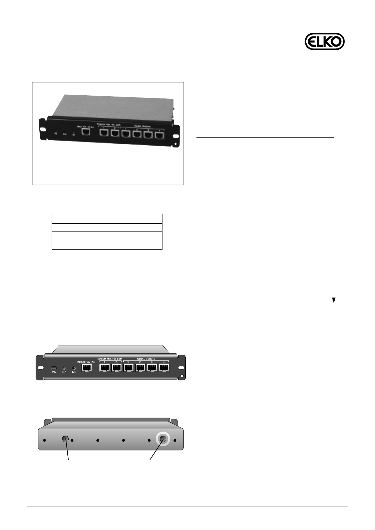
The module is a fully shielded unit made in 10'' format, 10'' wide and 1 Height unit. On the front, as
shown in Fig. 1, there are 7 shielded RJ45 ports
avail-able to the user. Also a green LED indication
for Power, adjustment for the gain, and an output for
the IR link are located on the front.
On the back of the module, as shown i fig 2, a 2
pole connector for Power supply ( 12 V DC ), a F
connector for the incomingt radio-/TV signals are
located.
NB 312
02.03.05
Rev.1.1
WF
R/TV Module EL 1030 (5-30 MHz)
ELKO P/N 6854 N 69 426 45
S 51 860 22 FIN 72 042 54
R/TV Module EL 1055 (5-55 MHz)
ELKO P/N 6860 N 69 426 69
S 51 860 26 FIN 72 042 50
R/TV Module EL 1065 (5-65 MHz)
ELKO P/N 6861 N 69 426 70
S 51 860 27 FIN 72 042 51
Type
EL 1030
EL 1055
EL 1065
Return Path
5 - 30 MHz
5 - 55 MHz
5 - 65 MHz
Figure 1: Front view of the Antenna module
Figure 2: Back view of the Antenna module
2 pole connector for
Power supply
F-connector for incoming
Radio-/TV signals
Page 6
COMMON
Power supply (external) :
Power Consumption:
Gain @ 862 MHz :
Attenuation :
Input impedance :
Output impedance :
Input level :
Output level :
No of TV-Channels :
Noise figure :
Isolation between outputs :
Return Path Gain :
CTB:
CSO:
Stop band attenuation :
AV link input level:
AV input frequency range:
Temperature (operating):
Standards :
12 volt DC ± 5% , (Negative (-) put to GND)
3,5 Watt
35 dB (on all 6 ports) ± 2 dB
0 – 20 dB
75 Ohms , F-connector
100 Ohms , Balanced
60 – 80 dB µV
114 dB µV x 6 (Measured according to DIN 45004-B)
41
< 6.5 dB @ 860 MHz
> 20 dB
6 dB
94 dB µV
88 dB µV
> 55 dB
90 dB µV
88-470 MHz
0 - 40 °C
EN 50083-3 , quality grade 2 , cat. C
EL 1030
Frequency range, forward
Return path
47 – 860 MHz
5 - 30 MHz
EL 1055
Frequency range, forward
Return path
70 – 860 MHz
5 - 55 MHz
EL 1065
Frequency range, forward
Return path
85 – 860 MHz
5 - 65 MHz
Technical specifications
Installation
• The cable (R/TV signals) carried to
the distribution board is connected
to the female F-connector (RF input)
on the module. (F-connector for the
cable is not supplied). The amplifier
module is to be regarded as an endoutlet.
• Power is connected from the ELKO
Link Home Power supply. The
module is protected against wrong
polarity.
• The output level is adjusted from the
Gain regulation. All output ports are
adjusted simultaneously. Tune to an
output level that ensures a signal
between 60 and 80 dBµV at the outlets of both the longest and the shortest links in the ELKO Link Home
installation. The gain adjust potentiometer is located between the power
indicator LED, and IR link port.
• There are no tilt adjustment since the
amplifier has a factory set equaliser
matching the cable attenuation. This
is performing optimal only on the
condition that the incoming signal
connected to the amplifier module
has a maximum tilt of 10 dB and
always lays in the area between 60
to 80 dBµV in terms of the signal
level.
Notice!
If opening the top cover screws, the
guarantee is no longer valid.
When connecting the radio- and TVappliances to the wall outlets, it is
necessary to use dedicated ELKO
Link Home connection cords. In these,
the conversion between the 100 Ohm
balanced cabling and the 75 Ohm
coaxial connections on R/TV appliances is carried out.
The 100 Ohm termination plug
MUST be fitted in the AV link port
when leaving the installation.
ELKO A/S, P. O.Box 234, N-1301 Sandvika, Tel: +47- 67 80 73 00 Fax: +47- 67 80 73 01
AB Elektrokontakt, Box 2093, 128 22 Skarpnäck, Tel. 08-447 33 70, Fax. 08-447 33 80
ELKO SUOMI OY, Olarinluoma 16 02200 ESPOO Tel +358 09 439 3210 Fax +358 09 4393 2120
 Loading...