

Elko CRM-91H, CRM-9S, CRM-93H User Manual
02-186/2016 Rev.: 1
1 / 2
CRM-91H
CRM-93H
CRM-9S
A1
16 18
26 28
36 38
S A2
1 5
2 5
3 5
CRM-93H
1 5
16 18
A1
S A2
CRM-91H CRM-9S
A1/B1
S A2
18
18
+
+
16 18
1 5
S A2
A1
Un
CRM-91H CRM-9S
+
15 16 18
A1 S A2
-
Un
CRM-93H
-
+
A1 S A2
35 36 38
25 26 28
15 16 18
Un
B1 18 18
A1 S A2
Un
cos φ ≥ 0.95
M M
HAL.230V
K
M M
cos φ ≥ 0.95
M M
HAL.230V
K
M M
AC12
250V / 10A
DC14
24V / 2A
AC1
250V / 16A
AC13
250V / 6A
AC2
250V / 5A
AC14
250V / 6A
AC3
250V / 3A
AC15
250V / 6A
AC5b
800W
DC5
24V / 4A
AC6a
x
DC12
24V / 16A
AC7b
250V / 3A
DC13
24V / 2A
AC12
250V / 1A
DC14
x
AC1
250V / 8A
AC13
x
AC2
250V / 3A
AC14
250V / 3A
AC3
250V / 2A
AC15
250V / 3A
AC5b
300W
DC5
24V / 2A
AC6a
x
DC12
24V / 8A
AC7b
250V / 1A
DC13
24V / 2A
CRM-93H
CRM-91H
Made in Czech Republic
Multifunction time relay
- Multifunction time relay can be used for electrical appliances, control of lights,
heating, motors, pumps and fans (10 functions, 10 time ranges, multi-voltage,
16 A or 3x 8 A contacts).
- Ful lls all requirements for time relays
- 10 functions: - 5 time functions controlled by supply voltage
- 4 time functions controlled by control input
- 1 function of latching relay
-
Comfortab le and well-arranged function and time-range set ting by rotary switches.
- Time scale 0.1 s - 10 days divided into 10 ranges: (0.1 s - 1 s / 1 s - 10 s / 0.1 min
- 1 min / 1 min - 10 min / 0.1 hrs - 1 hrs / 1 hrs - 10 hrs / 0.1 day - 1 day / 1 day 10 days / only ON / only OFF).
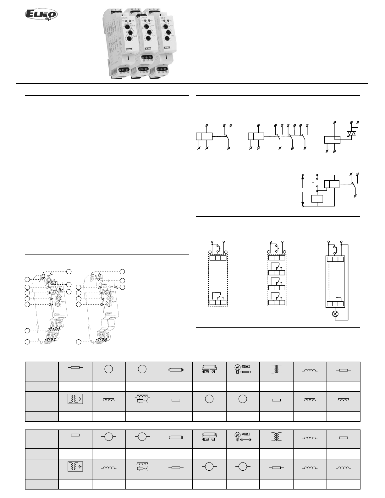
- CRM-91H, CRM-93H:
- universal supply voltage AC/DC 12 - 240 V or AC 230 V
- output contact: CRM-91H: 1x changeover/SPDT 16 A
CRM-93H: 3 x changeover/SPDT 8 A
- CRM-9S:
- universal supply voltage AC 12 - 240 V, absolutely noise-less switching.
- 1x static contactless output (triac) 0.7 A (60 A / <10 ms), switches potential A1.
- Multifunction red LED output indicator ashes or shines depending on the status
of output.
- 1-MODULE, DIN rail mounting.
Characteristic
Description
Symbol
Connection
Load
Possibility to connect load onto controlling input:
It is possible to connect the load (e.g.: contactor)
between terminals S-A2, without any interruption
of correct relay function.
AC5a
uncompensated
230V / 3A (690VA)
DC1
24V / 16A
AC5a
compensated
x
DC3
24V / 6A
Type of load
mat. contacts AgNi,
contact 16 A
Type of load
mat. contacts AgNi,
contact 16 A
AC5a
uncompensated
230V / 1.5A (345VA)
DC1
24V / 8A
AC5a
compensated
x
DC3
24V / 3A
Type of load
mat. contacts AgNi,
contact 8 A
Type of load
mat. contacts AgNi,
contact 8 A
1) Output contacts of CRM-93H do not allow switching of di erent phases or 3-phase
voltages (voltage > 250 V).
2) When mounting into steal-plated switchboards, it is necessary to keep a safety distance
of min. 3 mm from terminal’s screws 35-36-38 and 25-26-28 towards the shutter of a
switchboard.
Notes
CRM-93H
8
1
3
4
7
7
7
2
5
6
CRM-9S
1
83
4
7
2
5
6
1. Supply terminals
2. Control. input “S”
3. Supply indication
4. Rough time setting
5. Fine time setting
6. Function setting
7. Output contact
8. Output indication
ELKO EP, s.r.o.
Palackého 493
769 01 Holešov, Všetuly
Czech Republic
Tel.: +420 573 514 211
e-mail: elko@elkoep.com
www.elkoep.com
EN
2 / 2
CRM-91H CRM-93H CRM-9S
j
PULS PULStt
U
i
S
h
tttt
S
f
tt
S
a
tt
U
d
tt t t t t
U
c
tt t t t t
U
b
tt
U
e
tt
S
g
tt
S
Warning
Technical parameters
The device is constructed for 1-phase main installation of 230V AC or AC/DC 12-240 V,
CRM-9S is const ructed for conne ction for 1-phase m ain AC 12-240 and must be i nstalled in
accordance with regulations and standards applicable in the country of use. Installation,
connection, setting and ser vicing should be installed by quali ed electrician sta only,
who has learnt these instruction and functions of the device. This device contains
protection against overvoltage peaks and disturbancies in supply. For correct function
of the protection of this device there must be suitable protections of higher degree
(A,B,C) installed in front of them. According to standards elimination of disturbancies
must be ensured. Before installation the main switch must be in position “OFF” and
the device should be de-energized. Don´t install the device to sources of excessive
electro -magnetic interference. By correct installation ensure ideal air circulation so in
case of permanent operation and higher ambient temperature the maximal operating
temperature of the device is not exceeded. For installation and setting use screw-driver
cca 2 mm. The device is fully-electronic - installation should be carried out according to
this fact. Non-problematic function depends also on the way of transportation, storing
and handling. In case of any signs of destruction, deformation, non-function or missing
part, don´t install and claim at your seller it is possible to dismount the device after its
lifetime, recycle, or store in protec tive dump.
Example of time setting to 8 hours period:
For rough setting use time scale 1-10s on the potentiomenter.
For ne time setting aim for 8s on potentiometer, then recheck accuracy (using
stopwatch etc).
On rough time setting, set potentiometer to originally desired scale 1-10 hours, leave a
ne setting as it is.
More accurate setting of timing for long periods of time
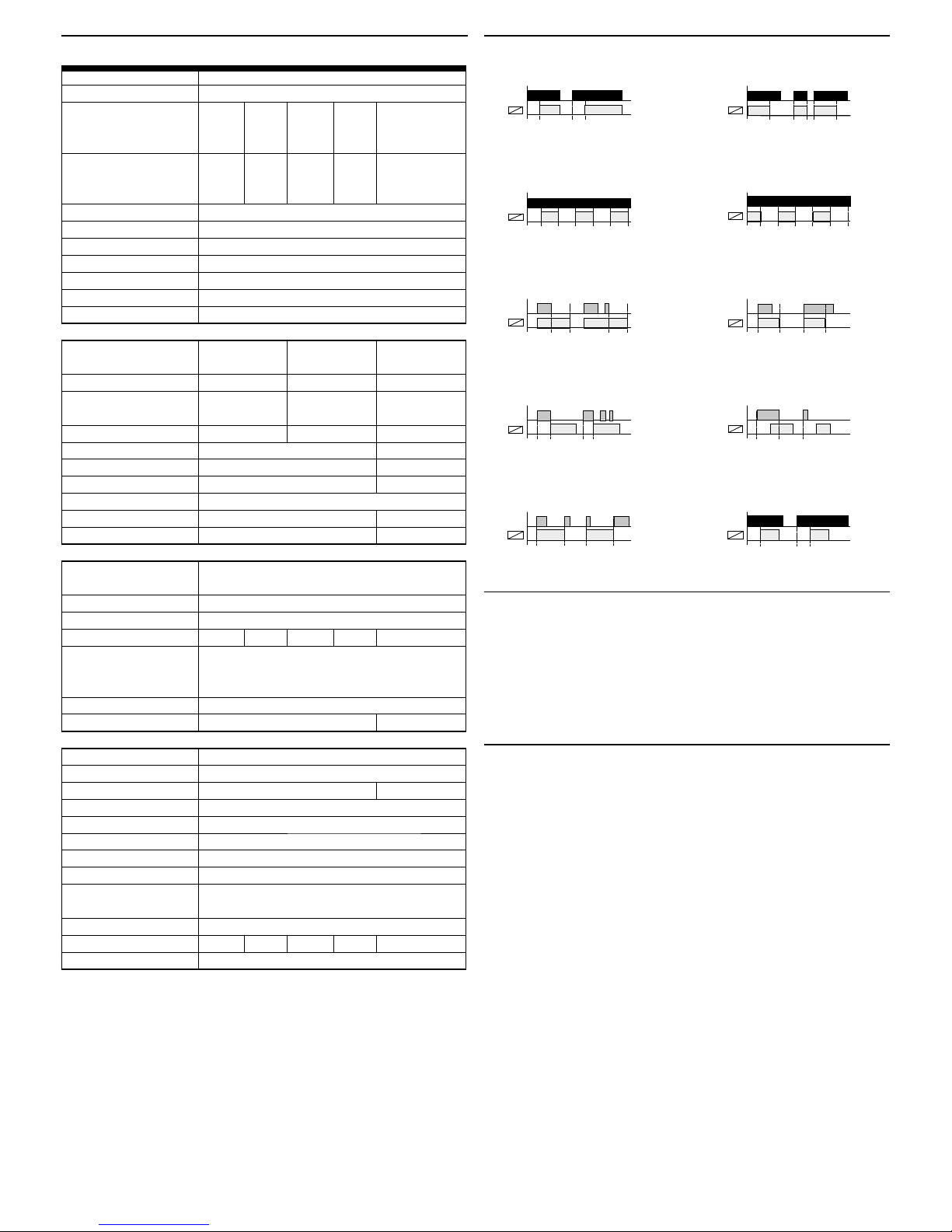
Functions
Number of functions:
Supply terminals:
Voltage range:
Consumption (apparent /
loss):
Supply voltage tolerance:
Supply indication:
Time ranges:
Time setting:
Time deviation:
Reeat accuracyp:
Tem pera tur e coe cient:
Output
Number of cont acts:
Current rating:
Breaking capacity:
Inrush current:
Switching vo ltage:
Switch drop:
Load-B1 terminal connect.:
Output indication:
Mechanical life:
Electrical life (AC1):
Controlling
Consumption of input:
Load bet ween S-A2:
Control. terminals:
Glow tubes connection:
Max. amount of glow lamps
connected to controlling
input:
Impulse length:
Reset time:
Other information
Operating temperature:
Storage tem perature:
Electrical strength:
Operatin g position:
Mounting:
Protection degree:
Overvoltage cathegory:
Pollution d egree:
Max. cab le size (mm
2
):
Dimensions:
Weight :
Standard s:
10
A1 - A2
AC/DC AC/ DC
12-240V (AC AC 230 V / 12-240V (AC AC230 V / AC 12-240 V
50-6 0 Hz) 50-60 Hz 50 -60 Hz) 50 -60 Hz (50-6 0 Hz)
AC 0.7 - AC max. AC 0.7 - AC ma x.
3 VA / DC 12 VA / 3 VA / DC 12 VA /
0.5-1.7 W 1.3 W 0.5 -1.7 W 1.9 W AC max. 0. 35 VA
-15 %; +10 %
green LED
0.1 s - 10 days
rotary switch and potentiometer
5 % - mechanical setting
0.2 % - set value stability
0.01 % / °C, at = 20 °C (0.01 % / °F, at = 68 °F)
1x changeover/ SPDT 3x changeover/ SPDT
1x s t a t i c c o n t a c t .
(AgNi / Silver Alloy) (AgNi / Silver Alloy) output (triac)
16 A/ AC1 8 A/ AC1 0.7 A
4000 VA / AC1, 2000 VA / AC1,
384 W / DC 192 W / DC x
30 A / <3s 10 A / <3s 60 A / <10 ms
250 V AC1/ 24 V DC x
x max. 0.9 V at I max.
x YES / I max. 0.7 A
multifunction red LED
3x10
7
> 10
8
0.7x10⁵ > 10
8
AC 0.025-0.2VA/DC 0.1-0.7W (UNI), AC 0.53VA (AC230 V),
AC 0.025-0. 2VA (AC12-240 V)
Yes
A1- S
No Yes No Yes No
UNI - glow lamps c annot connected / NO
230 V - max. 20 pc s
(measured with glow lamp 0.68 mA / 230 V AC)
min. 25 ms / max. unlimited
max. 150 ms max. 250 ms
-20 °C .. +55 °C
-30 °C .. +70 °C
4kV (supply -output) x
any
DIN rail EN 60715
IP40 from front panel / IP20 terminals
III.
2
solid wire max. 1x 2.5 or 2x 1.5 /
with sleeve ma x. 1x 2. 5 (AWG 12)
90 x 17.6 x 64 mm (3.5˝ x 0.7˝ x 2.5˝)
64 g (2.26 oz .) 62 g (2.2 oz.) 89 g (3.1 oz.) 87 g (3 oz .) 51 g (1.8 oz.)
EN 61812-1, EN 61010 -1
Delay ON after energisation
Delay OFF responding to make of
control contact regardless its length
Delay OFF after energisation
Cycler beginning with pause after
energisation
Cycler beginning with impulse after
energisation
Delay OFF after de-energisation, instant
make of output
Delay OFF after break of control contact
with instant output
Delay OFF after make and break of
control contact
Pulse generator (puls = 0.5s)Impulse relay
 Loading...