

Elko AirMD-100, AirMD-100L, AirMD-100NB, AirMD-100S Series Manual
ELKO EP, s.r.o.
Palackého 493
769 01 Holešov, Všetuly
Czech Republic
Tel.: +420 573 514 211
e-mail: elko@elkoep.com
www.elkoep.com
Made in Czech Republic
02-104/2017 Rev.: 0
EN
AirMD-100
AirKey
Motion detector
Key chain iNELS Air
Characteristics
AirMD-100
• The PIR motion detector is used to detect people moving in the interior.
• PIR sensitivity settings to eliminate unwanted switching.
• The detector o ers a quick and comfortable solution for detecting motion in an
object. It’s just a simple installation at the location.
• The Sigfox, LoRa or NB-IoT network can be used for message transmission.
• Anti-sabotage function (tamper): When unauthorized interference with the detector occurs (disassembly) it sends an information message to the server.
• Data is sent to the server from which it can be subsequently displayed as a smartphone, application, or Cloud noti cation.
• Battery status information is sent as a message to the server.
• Power supply: battery 2x 1.5 V AA.
• The Disarm is done either with a message from the server or by using the AirKey
key fob that communicates with the detector wirelessly.
AirKey
• It is used to activate and deactivate the motion detector when you enter or leave
the monitored area.
• One detector can be matched up to 32 key fobs. The key fob can be paired with any
number of detectors.
• Designed in black and white with laser printing.
• Battery power supply (3V/CR2032 - included in the supply) with battery life of
around 5 years based on frequency of use.
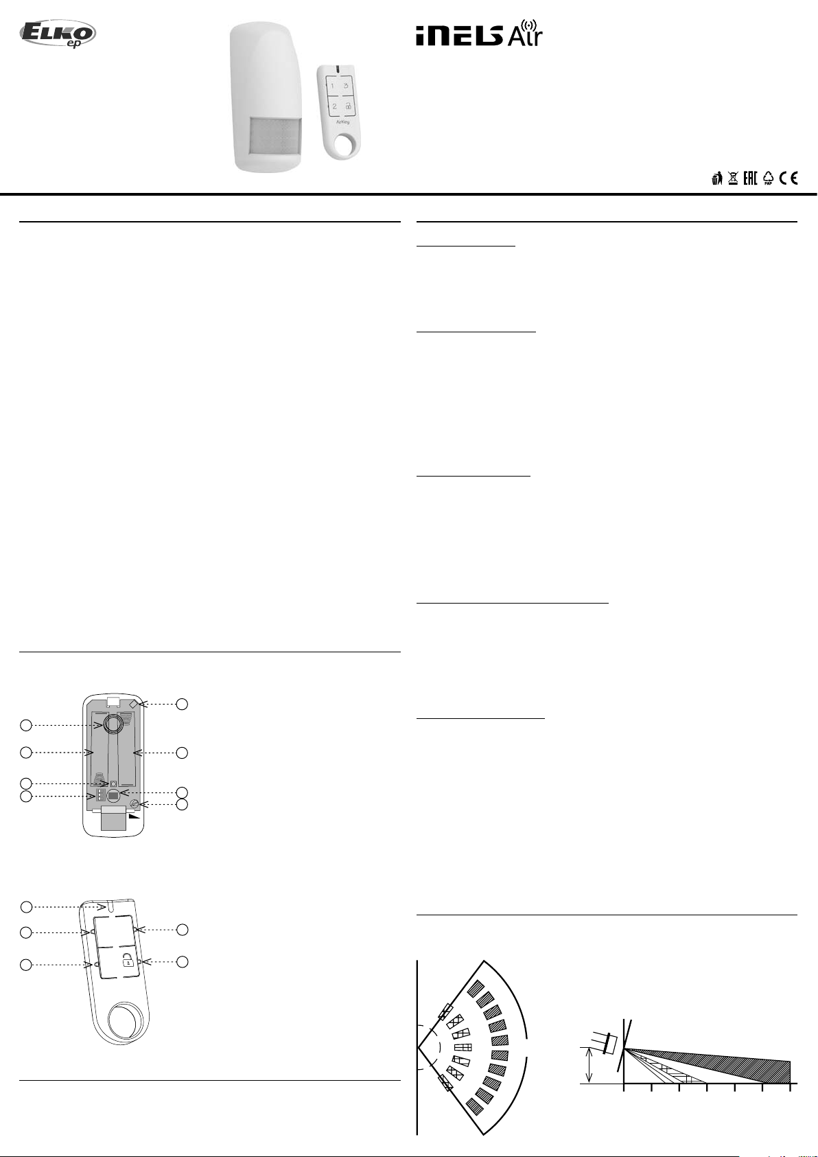
Description
AirMD-100
1. Antenna
5
1
2
3
4
+
+
1 2 3
ON
SENS
2. Battery
3. Blue LED
4. DIP Switch
2
6
7
- DIP1: no function
- DIP2: no function
- DIP3: programming / deleting the
detector memory
5. Tamper
6. Motion sensor
7. Setting SENS component- sensitivity
adjustment of the PIR sensor
General instrucions
Internet of Things (IoT)
• The IOT wireless communications category describes the Low Power Wide Area
(LPWA). This technology is designed to provide full-range coverage both inside and
outside buildings, energy-saving and low-cost operation of individual devices. Individual networks - Sigfox, LoRa, NarrowBand - are available to use this standard.
Sigfox network information
• The net work supports bidi rectional communicat ion but with a limited numbe r of feedbacks. It uses the free frequency band divided by Radio Frequency Zones (RCZ).
• RCZ1 (868 MHz) Europe, Oman, South Africa
• RCZ2 (902 MHz) Nor th America
• RCZ3 (923 MHz) Japan
• RCZ4 (920 MHz) South America, Australia, New Zealand, Singapore, Taiwan
• Sigfox has more coverage across countries, so it is better suited for long distance monitoring.
• For more information on this technology, please visit www.sigfox.com.
LoRa network information
• The network is bidirectional and its communication uses free frequency band.
• 865 - 867 MHz India
• 867 - 869 MHz Europe
• 902 - 928 MHz North America, Japan, Korea
• The advantage of this network is the possibility of freely deploying individual stations
in local locations, thus strengthening their signal. It can therefore be used e ciently in
company premises or, for example, in local parts of cities.
• For more information on this technology, please visit www.lora-alliance.org.
Information about the NarrowBand network
• The network provides two-way communication and the only one to use the licensed
LTE band. Our devices allow band 1 (2100MHz), Band 3 (1800MHz), Band 8 (900MHz),
Band 5 (850MHz), Band 20 (800MHz) and Band 28 (700MHz).
• It uses this SIM card technology for each device.
• The advantage of NarrowBand is the use of already built-up grids, which ensures su cient reception outside and inside buildings.
• For more information on this technology, please visit www.vodafone.cz
Caution for proper operation:
• Products are installed according to the wiring diagram given for each product.
• For proper device functionality, it is necessary to have su cient coverage of the selected network at the installation site.
• At the same time, the device must be registered in the network. Successful device registration on a given network requires a charge for tra c.
• Each network o ers di erent tari options - it always depends on the number of messages you want to send from your device. Information on these tari s can be found in
the current version of the ELKO EP pricelist.
AirKey
8
3
9
9
1
2
10
AirKey
8. Transmitter indication
9. Control button
9
10. Control button DISARM
Cloud app assignment
It is done in your Smar tphone application. Enter the relevant information on the product
cover into the application.
Detection fi eld
Top view Side view
12°
105°
max.
2.2 m
0 2 4 6 8 10 12 m
The detection area is covered by three cones
1 / 4
Function
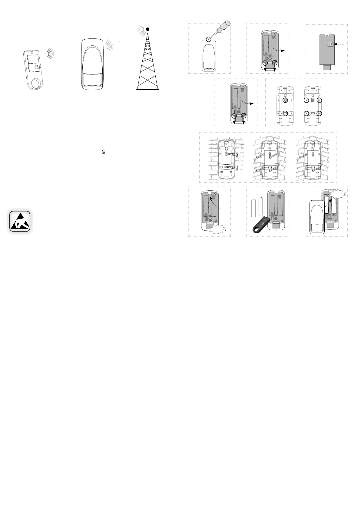
Assembly AirMD-100
RF
3
1
2
AirKey
AirKey AirMD-100
Base Transceiver
Station
If no movement is detected by the motion detector for 15 minutes, the guard will be
activated automatically.
Data status report sent at a max of four-hour intervals (You can edit the message from
the server).
Disarm (DISARM)
When capturing motion in the guard state, the blue LED lights up and an uninterrupted
beep sounds at the same time. Press the button
on the AirKey Controller. The audible
alarm is switched o and the transition to the DISARM status is con rmed by a short
beep.
If the guard is not switched o within 5 seconds, the audible alarm turns o and the
detector sends the alarm to the user.
If the detector is deactivated by the AirKey controller, it does not transmit the motion
detection information to the user.
Safe handling
When handling a device unboxed it is important to avoid contact with
liquids. avoi d unnecessary contac t with the component s of the device. Do
not touch the metal objects inside the unit.
AirMD-100NB
1
4
+
ON
a) b)
6
7
+
+
1 2 3
ON
Click!
a)
2
+
+
1 2 3
ON
a) b)
5
+
1 2 3
c)
8
+
-
+
+
-
+
1 2 3
ON
2
9
b)
AirMD-100NB
Click!
+
+
-
-
+
+
1 2 3
ON
1. Push the screwdriver into the opening at the top of the detector and open the device
cover.
2. Only with AirMD-100NB: Push the beaks (mouldings) on the setting component down
and remove the component from the base. Carefully insert nanoSIM (the device must
not be energized when inserting or replacing nanoSIM!)
3. You can attach the product either by sticking * on a at surface - apply a suitable adhesive to the outside of the base. Place the base in the desired location and let it dry.
4. Or using a suitable fastener ** by screwing. Push the beaks (mouldings) on the setting
component down and remove the component from the base.
5. Depending on the required location, remove the screw plugs from the base (e.g. with
a screwdriver).
a) To place on a at surface.
b) To place in a corner.
6. Place the base at the desired location and attach it with suitable bonding material according to the substrate**.
a) On a at surface.
b), c) into a corner.
7. Insert the component into the base and snap into place with pressure, gently.
8. Program the instrument (see chapter Programming the controller) and adjust the sensitivity of the PIR sensor.
9. Replace and snap the front cover.
Recommendations for installation
• When installing the detector, consider the handling area above the detector (to replace
the batteries, etc.). Do not exceed the maximum recommended height for placement.
• The detector is intended for indoor use.
• After inserting the bat tery, the time delay is 15 seconds to stabil ize the PIR detector, and
then the motion detection function is activated.
* The glue must meet the optimal conditions for product placement (in uence of tem-
perature, humidity ...)
** For example, a countersunk head screw can be used as a suitable fastener, screw of
max. Ø 3 mm.
 Loading...