

Page 1
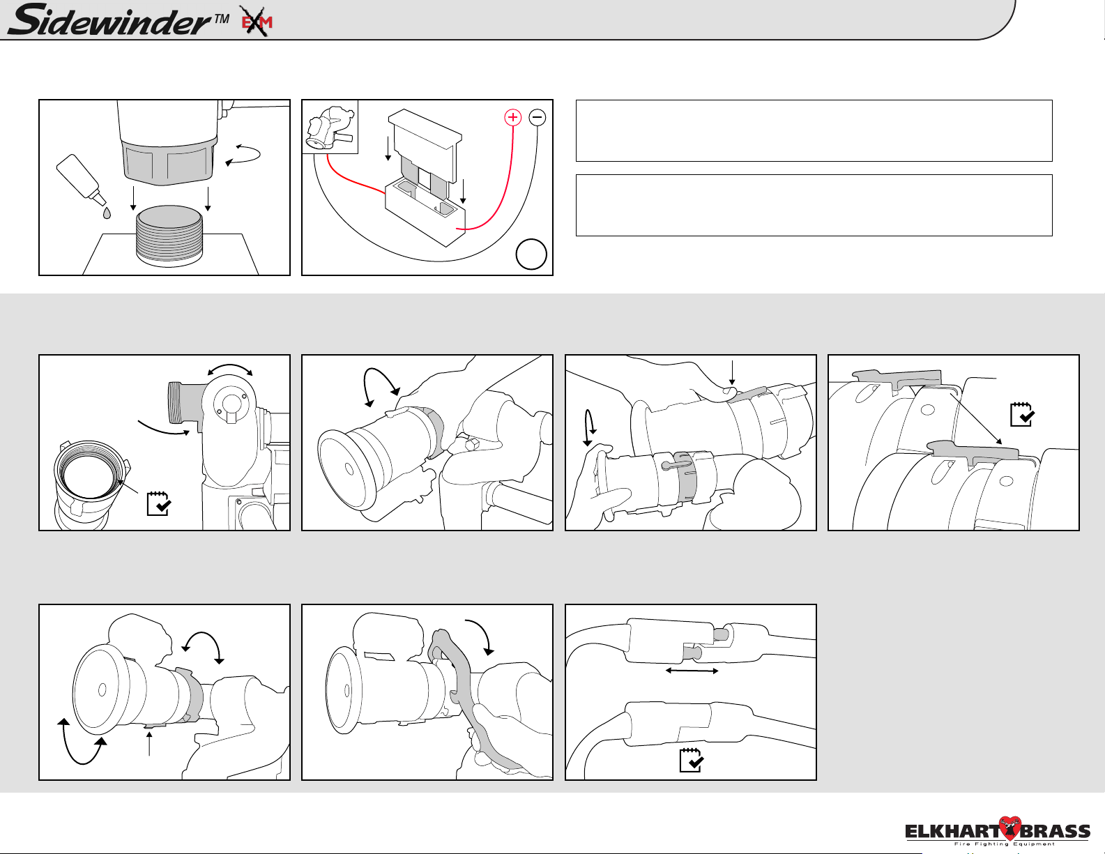
1.
A. Tighten Sidewinder EXM monitor to
base or Quick Connect using Loctite 592
thread sealant or equivalent.
2.
A. Position monitor discharge elbow
parallel to ground. Ensure gasket is
inside nozzle swivel.
90°
Quick Attack Pkg 1 Install Guide:
B. Add a 20A(12VDC)* fuse between
RED controller lead and positive power
lead.
B. Hand tighten nozzle to monitor using
swivel end piece.
*10A(24VDC)
NOTE: We recommend using 16 AWG for monitor power and ground. See
Sidewinder EXM monitor installation guide on page 8 of the manual for
length to gauge recommendations.
NOTE: If a Quick Connect is being installed, please refer to the Quick
Connect Install Guide. Guide can be found under the Sidewinder EXM
manual section at www.elkhartbrass.com.
16g
C. Adjust flow by pressing down on
locking lever and rotating nozzle to
desired flow setting.
Monitor & Nozzle
MONITOR
1
D. Confirm that locking lever is snapped
securely into position.
E. Loosen swivel and reposition nozzle
so the locking lever is on the very
bottom; 6 o’clock position.
3.
Confirm that all connections are tight and all electrical connections have been reconnected. If installing additional components,
such as controllers, you may choose to double check the connections after everything has been installed.
F. Tighten swivel using a spanner
wrench to ensure a secure connection.
G. Connect nozzle and monitor two-way
connectors.
NOZZLE
98326010 Rev. A
Page 2
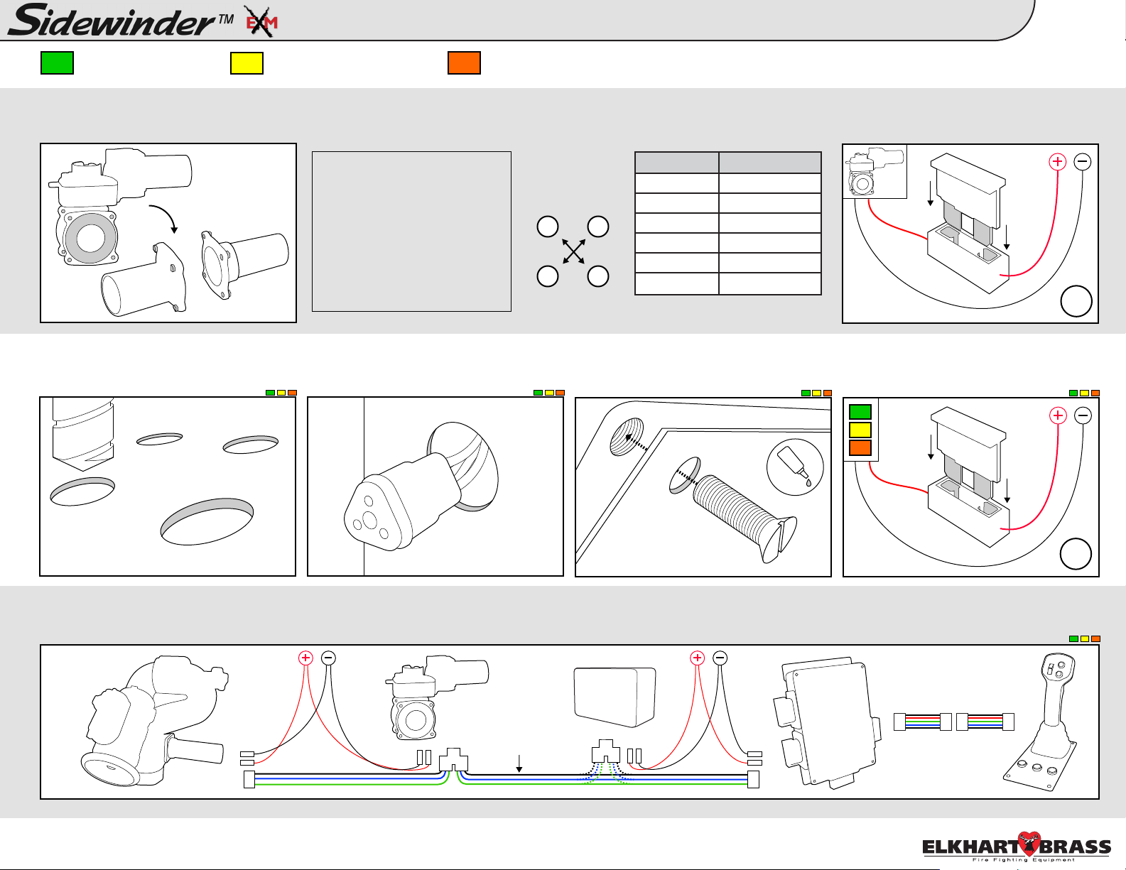
Quick Attack Pkg 1 Install Guide:
Control Components & Accessories
2
- Joystick Controller
A. Install valve into plumbing. Torque
4.
adapter bolts to spec using Figure 1.
A. Follow mounting templates on page
5.
30 of the instruction manual for hole
diameters and dimensions.
- OEM Interface Module - Position Feedback Display
NOTE: If you need to change
the orientation of the electric
actuator on top of the valve,
Tighten Adapter
Bolts using a
cross pattern
follow the instructions on
page 16 of the Unibody Valve
1 3
Manual (98311000). Manual
can be found at:
www.elkhartbrass.com/down
4 2
loads/manuals
B. Drill holes for CAN network and
power cables for each components’
leads behind each component.
C. Mount components to panel using
10-24 x 1/2” screws. Use Loctite 242 or
equivalent.
Valve Torque
EB15 2 5-30 ft-lbs
EB20 25-30 ft-lbs
EB25 25-30 ft-lbs
EB30 38-40 ft-lbs
EB35 38-40 ft-lbs
EB40 60-70 ft-lbs
Figure 1: Torque Specs
B. Add a 30A(12VDC)* fuse between
RED controller lead and positive power
lead.
*15A(24VDC)
16g
D. Add a 1A (12VDC)* fuse between
red component lead and positive power
*.5A (24VDC)
lead.
7/32” dia.
unless noted
A. Connect entire CAN network together using 18-22 AWG. Ensure every component connected to the CAN network is connected in between 2 end components that
6.
have CAN termination. Please refer to the BLUE, GREEN, and BLACK lines as the CAN wires below.
o
o
o
o
o
o
o
o
o
o
o
o
o
o
o
o
o
o
o
o
o
o
o
o
o
o
o
o
o
o
o
o
o
o
o
o
o
o
o
o
o
o
o
o
o
o
o
o
o
CAN
Network
Wires
98326010 Rev. A
18g
Page 3

NOTE: You will
also need to
calibrate the
valve before use.
While you are
NOT in setup
mode, press and
hold <Preset>
and <Close> for
approximately 5
seconds. The
valve will
a u t o m a t i c a l l y
start to calibrate
itself.
The following
steps are
optional (O).
Pressing the
<Osc> button will
cycle through the
monitor motor
speed options:
LEDs - Ver / Hor
0 - Fast / Fast
1 - Slow / Fast
2 - Fast / Slow
3 - Slow / Slow
Lower Left:
Move to top/right
corner of the
lower left zone,
hold <Preset>,
press <Close>,
and release both.
Lower Right:
Move to top/left
corner of the
lower right zone,
hold <Preset>,
press, <Open>,
and release both.
3 4 5
6
Quick Attack Pkg 1 Install Guide:
CALIBRATE VALVE
Close
Preset
SET MONITOR SPEED
(O)
SET KEEP-OUT ZONES
(O)
Lower Right Zone:
Top left corner
Lower Left
Zone
0°
Lower Left Zone:
Top right corner
Lower Right
Zone
Right Travel LimitLeft Travel Limit
Press and hold
<Aux> and
<Preset> until the
blue status LED
on monitor box
turns on.
NOTE: Changes
made will not
take effect until
after exiting
setup mode.
Move monitor to
a travel limit
position. Hold
<Stream>, and
move the joystick
forward to set the
lower limit, and
pull back to set
the upper limit.
MAX travel of
135° below the
pr e - c a l ib r a t e d
“zero” position.
Move monitor to
desired position,
then press <Fog>
and <Osc> at the
same time to
store a stow
position.
Stow position
must be within
allowed limits of
travel.
7
Setup Mode
CALIBRATE HORIZONTALENTER SETUP MODE
Preset
STATUS POWER
This step is
required (R).
Aim monitor at
center forward
“zero” position.
Hold <Preset>,
then move the
joystick to the
<Left> or <Right>
and hold until
status LED on
monitor blinks &
returns to solid.
(R)
Left
Right
Preset
21
SET VER TRAVEL LIMIT SET HOR TRAVEL LIMIT
(O)
L
Stream
U
Down
Up
SET STOW POSITION
(O)
Move monitor to
a travel limit
position. Hold
<Stream>, and
move the joystick
left to set the left
limit, and to the
right to set the
right limit.
MAX travel of
175° in either
direction from the
calibrated “zero”
position.
Press and hold
<Aux> and
<Preset> until the
blue status LED
on monitor box
turns off.
(O)
L
Left
Stream
EXIT SETUP MODE
Preset
STATUS POWER
R
Right
8
98326010 Rev. A
3
Page 4
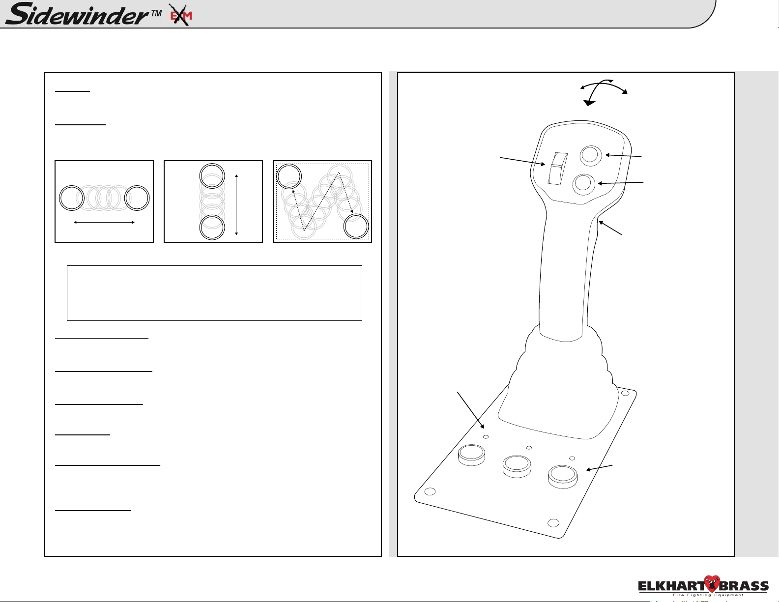
Quick Attack Pkg 1 Install Guide:
Button Press Logic: Joystick Joystick Layout:
To Stow
Hold <Fog> and <Osc> until monitor begins to stow.
To Oscillate
Press the <Osc> button at both extremities of the desired oscillation
pattern.
Horizontally Vertically Two Axis Oscillation
NOTE: You can manually control nozzle position while in a single
axis oscillation. Example: Up and Down will allow you to manually
control the vertical axis while in a horizontal oscillation. Any
direction in a two axis oscillation will stop the oscillation.
Nozzle Pattern
• Fog
• Stream
Button Press Logic
Left
Up
4
Down
Right
AUX
OSC
Valve Position (Trigger)
• Open (Pull)
• Close (Release)
Left, Right, Up, Down
These function normally
Fog & Straight Stream
These function normally
Valve Open & Close
These function normally
Valve Preset
Opens or closes valve to a predetermined position
To Change Valve Preset
Open or close the valve to the desired position. Press and hold the
<Preset> button until the preset light blinks (approx 10 seconds).
Valve Auto Travel
To auto travel OPEN, hold the <Open> button, then press <Close>, and
release both. The valve should fully open automatically. To CLOSE,
hold the <Close> button, then press <Open>, and release both.
BUTTON LOGIC
Valve Position LEDs
Valve Position Buttons
Close
Preset
Open
JOYSTICK
98326010 Rev. A
 Loading...