

Page 1

Technical Manual
for
1.5 VARI-NOZZLE, FIRE HOSE
DEFENSE CONSTRUCTION SUPPLY CENTER
NSN: 4210-00-465-1906
CAGE: 20266
MFR/PN: SFL-GN-95
ISSUED: 12-94
ELKHART BRASS MFG. CO. INC.
1302 W. Beardsley Avenue
Elkhart, Indiana 46514
98043300 REV-A
Page 2
Please refer to FIGURE 1 on page 7.
I. Operating Instructions
A. The nozzle is put into operation by first checking that
the Nozzle Tip is in the Wide Angle Fog position and
the Horshu-Handle is in the “CLOSED” position.
1. Rotate the Nozzle Tip by grasping the Hand
Grip and turning it counter clockwise until the
bottom of the Locking Lever is resting in the
notch directly below the Wide Angle Fog symbol
on the Nozzle Tip.
2. Push the Horshu-Handle as far forward as
possible to place it in the “CLOSED” position.
B. The nozzle-man should activate the water supply.
C. The nozzle-man (with hose team) should then
advance the nozzle toward the fire, but short of
engagement.
WARNING: The nozzle and hose line should be fully
manned (at least 2 men) before engaging the fire.
2
Page 3

D. The nozzle-man should then
slowly move the
Horshu-Handle from the “CLOSED” to the “OPEN”
position with the nozzle aimed in the direction of the
fire.
Slowly pull the Horshu-Handle as far back as
1.
possible to place it in the “OPEN” position.
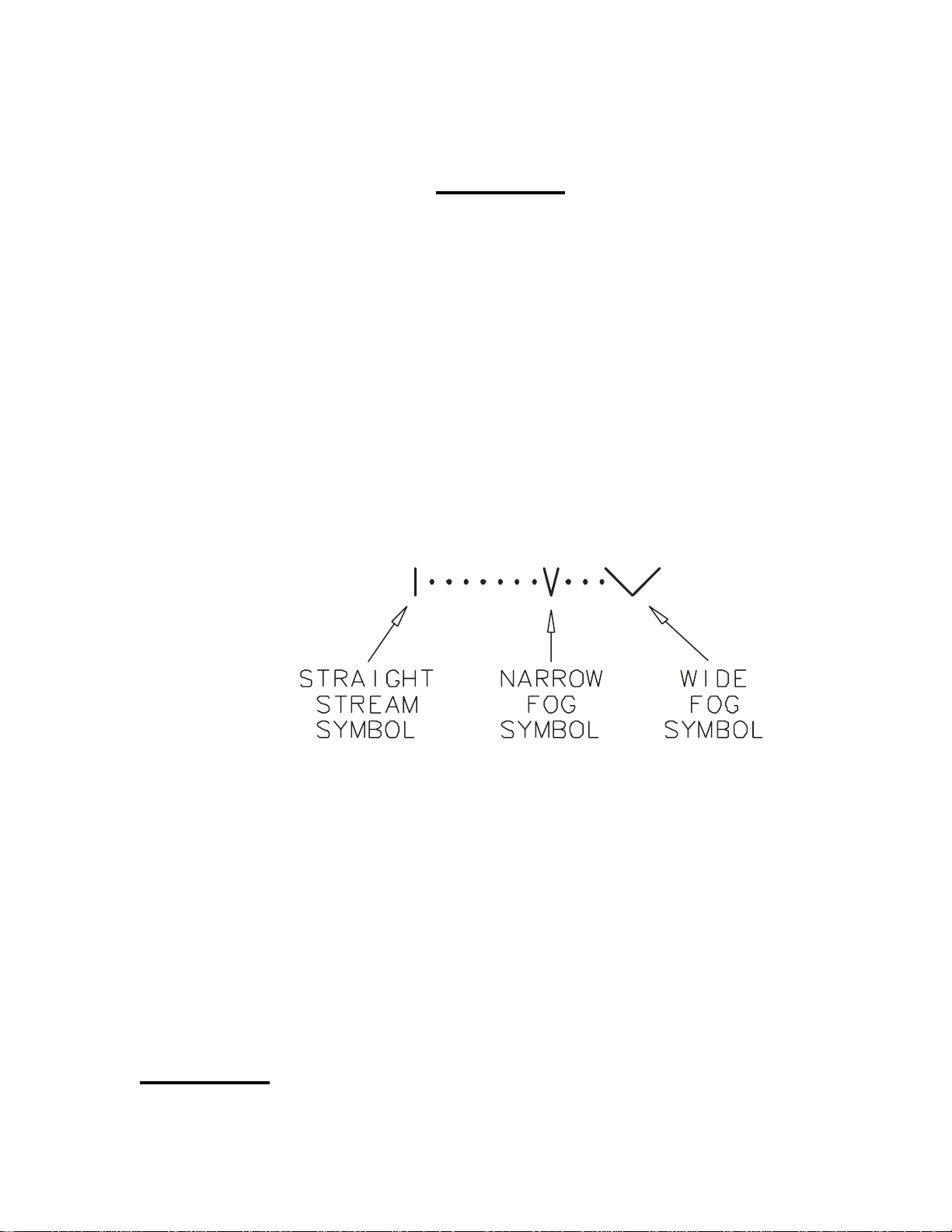
E. The nozzle-man should then test the operation of the
nozzle by rotating the Nozzle Tip from the Wide Angle
Fog stream pattern position to the Narrow Fog position
and on to the Straight Stream position and then reverse
direction and go back to the Wide Angle Fog stream
pattern position. The nozzle-man should stop at each
stream pattern position long enough to inspect the
stream pattern. Each of the fog pattern positions should
produce a complete conical shaped pattern with no
gaps or disruptions. If gaps or disruptions are observed
in any pattern position the nozzle should be checked for
debris or damage (see Section IV).
CAUTION: The Nozzle Tip must be returned to the Wide
Angle Fog pattern position before preparing to advance the
hose team into an engagement with the fire.
F. The nozzle is now ready for operation. Refer to
Command Firefighting Doctrine for application.
II. Making Ready for Service
A. After each use the nozzle should be removed from
the hose while the hose is being drained and stored.
3
Page 4

B. The nozzle should be cleaned with a mild detergent
and nylon bristled brush. The nozzle should then be
inspected for damage (see Section III).
CAUTION: Petroleum based solvents are not recommended
for cleaning the nozzle. Using petroleum based solvents on
components such as the O-rings, gaskets, or the Hand Grip
may cause degradation resulting in premature failure.
C. The nozzle should then be attached to the stored
hose, with the Horshu-Handle placed in the “CLOSED”
position and the Nozzle Tip placed in the Wide Angle
Fog position.
D. Where practical, the nozzle should be stored with the
discharge down to prevent contaminants from collecting
in the nozzle.
III. Inspection of Nozzle
Nozzle Tip rotation: Rotate Nozzle Tip through all
A.
positions several times. The Nozzle Tip should not bind
or stick. Return Nozzle Tip to the Wide Angle Fog
position.
B.
Flush feature: Depress the pad on the Locking
Lever until the blade on the bottom of the Locking
Lever disengages from the notch in the Center Barrel
and rotate the Center Barrel counter clockwise as far
as possible. Release the Locking Lever and rotate the
Center Barrel back clockwise until the blade of the
Locking Lever snaps back down to engage the notch
in the Center Barrel. Repeat several times. The Center
Barrel should not bind or stick and the Locking Lever
4
Page 5

should snap back down to engage the notch in the
Center Barrel every time. If Locking Lever fails to
snap back down to engage the notch in the Center
Barrel replace the nozzle.
Shut-off Valve: Move the Horshu-Handle from the
C.
full forward “CLOSED” position to the full back “OPEN”
position and back several times. The Horshu-Handle
should not bind or stick.
Nozzle Sealing: With water pressure on and the
D.
Horshu-Handle in the “CLOSED” position water should
not exit the nozzle, either through the discharge end or
any of the sealed joints. If leakage of more than 5 drips
per minute occurs the nozzle should be replaced.
IV. Troubleshooting
A. Uneven stream pattern or gaps in stream pattern.
Pattern affected in all stream positions and affected
area does not rotate with the turning of Nozzle Tip.
The most likely cause of this problem is debris lodged
inside the nozzle. Flushing the nozzle with water
flowing may correct the problem. While the nozzle is
flowing water, depress the pad on the Locking Lever
until the blade on the bottom of the Locking Lever
disengages from the notch in the Center Barrel and
rotate the Center Barrel counter clockwise as far as
possible. Release the Locking Lever and rotate the
Center Barrel back clockwise until the blade of the
Locking Lever snaps back down to engage the notch
in the Center Barrel. Inspect stream pattern, if it is still
affected the debris may be too large to pass through
5
Page 6

the nozzle in the flush position. The water supply
should be secured and the nozzle disconnected from
the hose so the debris can be removed from the inlet
end of the nozzle.
B. Uneven stream pattern or gaps in stream pattern.
Pattern affected in all stream positions and affected
area rotates with the turning of Nozzle Tip.
The most likely cause of this problem is damage to the
Nozzle Tip. Inspect the metal teeth and the inside
diameter of the Nozzle Tip, on the discharge end, for
damage. If damaged the nozzle should be replaced,
C. Leakage at the connection of the nozzle inlet to the
hose coupling.
This may be caused by a worn gasket in the Free
Swivel Base of the nozzle. Replace the gasket and
retest the connection. If leakage continues look for
damage to the threads or surfaces that contact the
gasket. Replace the nozzle if the threads or gasket
surface are damaged. Replace or repair the hose
coupling if the threads or gasket surface are damaged.
6
Page 7

FIGURE 1
7
Page 8

8
 Loading...