

Elkay EZ Series, LZ Series, EZSTLG8WS*1A Series, LZSTLG8WS*1A Series Installation, Care & Use Manual [en, fr, es]
Page 1
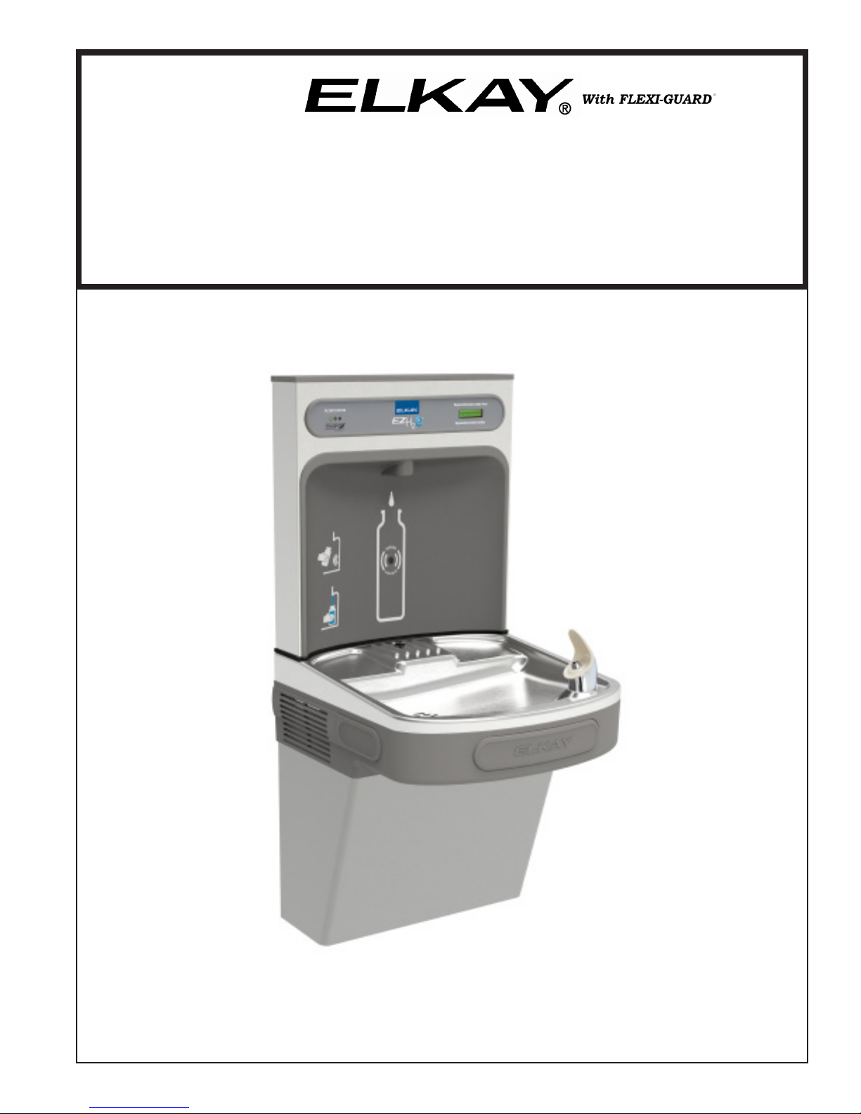
EZSDWS*1F EZS8WS*1F, 2F, 3F LZSDWS*1F, 2F, 3F LZS8WS*1F, 2F, 3F
INSTALLATION, CARE & USE MANUAL
Manual de Instalación, Cuidado y Utilización
Manuel d’installation/entretien/utilisation
TM
EZ
& LZ
TM TM
EZ & LZ Serie Botella Bombas y Enfriadores
EZ & LZ Stations de Remplissage de Bouteille Série et Refroidisseurs
TM
Series Bottle Filling Stations & Coolers
TM TM
Page 1 1000001731 (Rev. C - 01/15)
Page 2
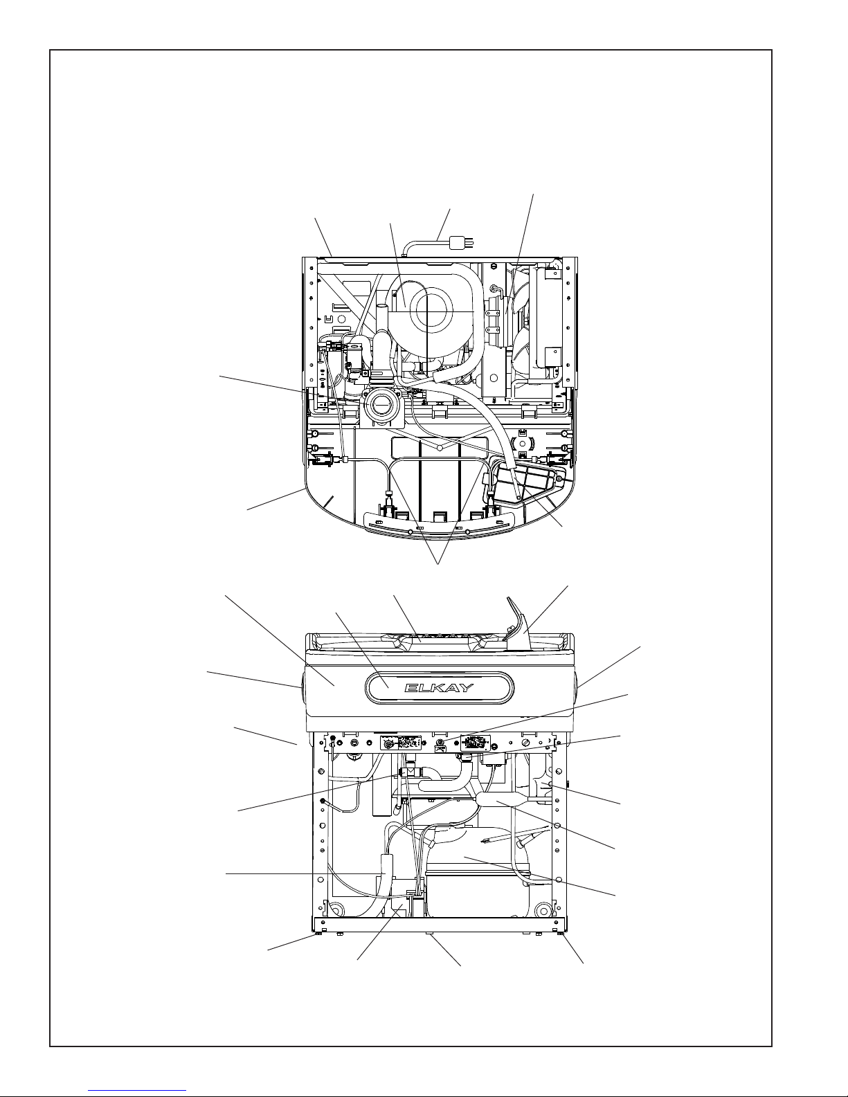
EZSDWS*1F EZS8WS*1F, 2F 3F LZSDWS*1F, 2F, 3F LZS8WS*1F, 2F, 3F
Pictured is unit only without bottle ller.
Uses HFC-134A refrigerant
Usa refrigerante HFC-134A
Utilise du uide frigorigéne HFC-134A
8
15
1
21
14
See Fig. 3
12
18
19
21
6
5
3
2
See Fig. 13
12
12
13
23
16
7
4
19
1000001731 (Rev. C - 01/15)
20
Fig. 1
Page 2
17
19
Page 3
EZSDWS*1F EZS8WS*1F, 2F, 3F LZSDWS*1F, 2F, 3F LZS8WS*1F, 2F, 3F
*ADA REQUIREMENT
2"
18 7/8"
479mm
90mm
3 9/16"
19"
483mm
HANGER BRACKET
51mm
8 1/16"
205mm
3"
77mm
5 7/8"
150mm
C
12 1/2"
318mm
27"
ADA
*
686mm
REQUIREMENT
*REQUISITO DE A.D.A.
*EXIGENCE ADA
RIM
HEIGHT
31 5/16"
796mm
HEIGHT
32 7/8"
ORIFICE
835mm
2 7/8"
73mm
15"
381mm
2"
51mm
E
A
732mm
28 13/16"
13 15/16"
7"
178mm
17 7/8"
454mm
7"
178mm
6 3/8"
162mm
L
C
6 3/8"
162mm
2"
51mm
2"
3 7/8"
98mm
51mm
FINISHED FLOOR
354mm
7"
5 3/4"
178mm
146mm
7"
178mm
CAJA RECESIVA DE ALAMBRES (3) DE SUMINISTRO ELÉCTRICO
BOÎTE ENCASTRÉE D’ALIMENTATION ÉLECTRIQUE (3) FILS
DE VENTILACIÓN DEL MUEBLE Y LA PARED.
ASSUREZ-VOUS UNE BONNE VENTILATION EN GARDANT 6” (152 mm) (MIN.) ENTRE LES ÉVENTS DE L’ENCEINTE ET LE MUR.
AGUJEROS DE LAS TUERCAS DE 7/16 PARA SUJETAR LA UNIDAD A LA PARED
TROUS D’ÉCROUS 7/16 POUR FIXER L’APPAREIL AU MUR
LEGEND/LEYENDA/LÉGENDE
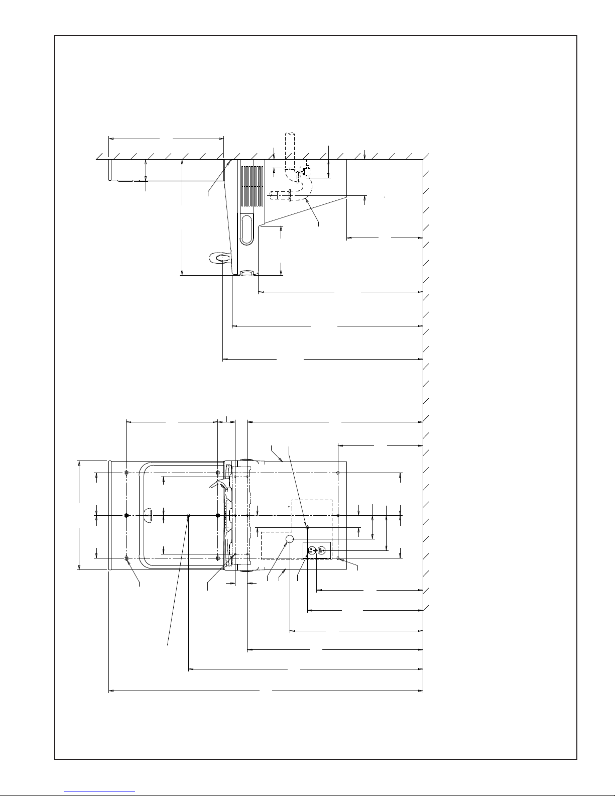
D = ELECTRICAL SUPPLY (3) WIRE RECESSED BOX**
E = INSURE PROPER VENTILATION BY MAINTAINING 6” (152 mm) (MIN.) CLEARANCE FROM CABINET LOUVERS TO WALL.
ASEGURE UNA VENTILACIÓN ADECUADA MANTENIENDO UN ESPACIO E 6” (152 mm) (MÍN.) DE HOLGURA ENTRE LA REJILLA
F = 7/16 BOLT HOLES FOR FASTENING UNIT TO WALL
**NEW INSTALLATIONS MUST USE GROUND FAULT CIRCUIT INTERRUPTER (GFCI)
**Las nuevas instalaciones deben utilizar el interruptor de circuito de tierra de la avería (GFCI)
**Les nouvelles installations doivent employer l’interrupteur de circuit moulu de défaut (GFCI)
F
B
2"
51mm
9/32"O HOLES
(7mm) (12)
7/16" X 3/4" OBROUND
(11mm X 19mm) HOLES (6)
ACTIVATION
SENSOR
D
E
17 7/16"
443mm
19"
483mm
21 7/8"
556mm
732mm
28 13/16"
38 1/2"
979mm
* REDUCE HEIGHT BY 3 INCHES FOR INSTALLATION OF CHILDRENS ADA COOLER
51 9/16"
1310mm
(76mm) MAXIMUM OUT FROM WALL
APAGO (POR OTROS) 3 en. (76 Mm) el MAXIMO FUERA DE PARED
(PAR LES AUTRES) 3 dans. (76 mm) le MAXIMUM HORS DU MUR
UBICACIÓN RECOMENDADA PARA EL DRENAJE DE SALIDA DE AGUA, DE 1¼” DE DIÁMETRO. El TALONARIO 2 FUERA DE PARED
EMPLACEMENT RECOMMANDÉ POUR LE DRAIN DE D.E. 1-1/4” DE SORTIE D’EAU. STUB 2 HORS DU MUR
PURGADOR DE 1¼” NO PROPORCIONADO
SIPHON 1-1/4” NON FOURNI
CAJA RECESIVA DE ALAMBRES (3) DE SUMINISTRO ELÉCTRICO
Fig. 2
LEGEND/LEYENDA/LÉGENDE
A = RECOMMENDED WATER SUPPLY LOCATION 3/8 O.D. UNPLATED COPPER TUBE CONNECT STUB WITH SHUT OFF (BY OTHERS) 3 IN.
La UBICACION 3/8 O RECOMENDADA de ABASTECIMIENTO DE AGUA. D. El TUBO del COBRE de UNPLATED CONECTA TALONARIO CON
L’O.D de 3/8 d’EMPLACEMENT DE PROVISION D’EAU RECOMMANDE. LE TUBE DE CUIVRE DE UNPLATED CONNECTE STUB AVEC ETEINT
B = RECOMMENDED LOCATION FOR WASTE OUTLET 1-1/4” O.D. DRAIN STUB 2 IN. OUT FROM WALL
C = 1-1/4” TRAP NOT FURNISHED
BOÎTE ENCASTRÉE D’ALIMENTATION ÉLECTRIQUE (3) FILS
D = ELECTRICAL SUPPLY (3) WIRE RECESSED BOX**
Page 3 1000001731 (Rev. C - 01/15)
Page 4

EZSDWS*1F EZS8WS*1F, 2F 3F LZSDWS*1F, 2F, 3F LZS8WS*1F, 2F, 3F
HANGER BRACKETS & TRAP
INSTALLATION
1) Remove hanger bracket fastened to back of
cooler by removing one (1) screw.
2) Mount the hanger bracket as shown in Figure 2.
NOTE: Hanger Bracket MUST be supported secure-
ly. Add xture support carrier if wall will not provide adequate support. Anchor hanger securely
to wall using all six (6) 1/4 in. dia. mounting holes.
IMPORTANT:
5-7/8 in. (150mm) dimension from wall to centerline
of trap must be maintained for proper t.
INSTALLATION OF COOLER
3) Hang the cooler on the hanger bracket. Be certain the hanger bracket is engaged properly in
the slots on the cooler back as shown in Figure
2.
4) Remove the four (4) screws holding the lower
front panel at the bottom of cooler. Remove the
front panel by pulling straight down and set aside.
5) Connect water inlet line--See Note 4 above.
6) Install trap. Remove the slip nut and gasket from
the trap and install them on the cooler waste line
making sure that the end of the waste line ts into
the trap. Assemble the slip nut and gasket to the
trap and tighten securely.
IMPORTANT: If it is necessary to cut the drain,
loosen the screw at the black rubber boot and
remove tube, check for leaks after re-assembly.
7) Plug in electrical power. Unit must have
electrical power to have water ow.
START UP
Also See General Instructions
8) Stream height is factory set at 35 PSI. If supply
pressure varies greatly from this, adjust screw
located on the left side below push bar ass’y. on
crossbar. CW adjustment will raise stream and
CCW adjustment will lower stream. For best ad-
justment, stream should hit basin approximately
6-1/2” (165mm) from bubbler on the downward
slope of the basin.
NOTE: If continuous ow occurs at the end of the
compressor cycle, turn cold control counterclockwise 1/4 turn.
9) Replace the front panel ensuring that the metal
wrapper is secured inside of the upper shroud.
Replace all four screws previously removed.
CLEANING
Warm, soapy water or mild household cleaning
products can be used to clean the exterior
panels of the EZ coolers. Extra caution should
be used to clean the mirror nished stainless
steel panels. They can be easily scratched and
should only be cleaned with mild soap and water
or Windex glass cleaner and a clean, soft cloth.
Use of harsh chemicals or petroleum based or
abrasive cleaners will void the warranty.
INSTALACIÓN DE LOS SOPORTES
FIJADORES Y EL PURGADOR
1) Retire el soporte jador que se encuentra conectado
a la parte posterior del enfriador sacando un (1)
tornillo.
2) Monte el soporte jador de la manera descrita en
Fig. 2.
NOTA: Es necesario que el soporte jador sea
apoyado seguramente. Agregue un portador al
soporte jador si La pared no aporta soporte
adecuado. Amarre el soporte colgante
seguramente a la pared. Usando todos los seis
(6) agujeros de montaje de ¼ pulg. (63.5 mm)
de diám.
IMPORTANTE:
Es necesario mantener una distancia de 5-7/8
pulg. (150mm) de la pared a la línea central
del purgador para poder obtener un ajuste
correcto.
INSTALACIÓN DEL ENFRIADOR
3) Cuelgue el enfriador en el soporte colgante.
Asegúrese que el soporte colgante está
enganchado adecuadamente en las ranuras
en la parte posterior del enfriador según
descrito en Figura 2.
4) Retire los cuatro (4) tornillos que sujetan el
panel frontal inferior en el pie del enfriador.
Retire el panel frontal al jalarlo hacia abajo y
póngalo al lado.
5) Conecte la tubería de entrada de agua –
Consulte la Nota 4 de la Instrucciones
Generales.
6) Instale el purgador. Retire la tuerca
deslizante y el obturador del purgador e
instálelos en la tubería de descarga del
enfriador, asegurándose de que el extremo de
la tubería de descarga encaje en el purgador.
Ensamble la tuerca deslizante y el obturador
en el purgador y apriete rmemente.
IMPORTANTE: Si llega a ser necesario cortar la
tubería de descarga, aoje el tornillo en el
fuelle negro de goma y retire la tubería,
después del reensamblaje, compruebe que
no haya pérdidas.
7) Enchufe la alimentación eléctrica.
INICIO
También consulte las
Instrucciones Generales
8) La altura del chorro viene predenida de la
fábrica en 35 psi. Si la presión de la fuente
varía grandemente de esto, ajuste el tornillo
situado en el lado izquierdo debajo de la
barra del empuje ass’y. en la barra transver
sal. Un ajuste en el sentido de las manecillas
del reloj alzará al chorro y un ajuste en el
sentido contrario a las manecillas del reloj
bajará el chorro. Para lograr el mejor ajuste,
el chorro debe caer al estanque
aproximadamente un 6-1/2 pulg. (165 mm)
del grifo en la inclinación hacia abajo del
estanque.
NOTA: Si ocurre un ujo continuo al n del
ciclo del compresor, gire el control del agua
fría una cuarta vuelta en el sentido contrario a
las manecillas del reloj.
9) Reemplace el panel frontal asegurando que la
envoltura metálica está bien sujetada adentro
de la cubierta superior. Reemplace todos los
cuatro tornillos previamente retirados.
INSTALLATION DES SUPPORTS
DE SUSPENSION ET DU SIPHON
1) Retirez le support de suspension xé au dos du
refroidisseur en retirant une (1) vis.
2) Montez le support de suspension comme indiqué
dans la gure 2.
REMARQUE: Le support de suspension doit être
accroché sûrement. Renforcez le soutien du mur
par l’ajout d’un élément porteur xe si le mur ne
peut pas, à lui tout seul, offrir un soutien sufsant.
Fixez le support au mur en utilisant des trous de
xation de 6 pouces ¼ de diamètre.
IMPORTANT:
Une distance de 5 à 7 pouces (150 mm) entre le
mur et l’axe du siphon doit être respectée pour
assurer une pose correcte.
INSTALLATION DU REFROIDISSEUR
3) Pendez le refroidisseur au support de
suspension. Assurez-vous que le support est
correctement inséré dans les emplacements au
dos du refroidisseur, comme indiqué dans la
gure 2.
4) Retirez les four (4) vis maintenant en place le
panneau frontal au bas du refroidisseur.
Retirez le capot inférieur en tirant vers le bas et
mettez-le de côté.
5) Reliez l’alimentation en eau — Référez-vous à la
remarque 4 des Instructions Générales.
6) Mettez en place le siphon. Retirez l’écrou
coulissant et le joint statique du siphon et
installez-les sur la conduite résiduaire du
refroidisseur en vériant bien que l’extrémité de
la conduite résiduaire entre dans le siphon.
Installez l’écrou coulissant et le joint statique au
siphon et serrez fortement.
IMPORTANT: Au cas où il serait nécessaire de
couper le drain, déserrez la vis située sur la
gaine noire en caoutchouc et retirez le tube,
puis vériez qu’il n’y a pas de fuites avant de
remonter.
7) Branchez l’alimentation électrique.
DEMARRAGE
Voir également le chapitre
Instructions Générales
8) La pression de la vapeur a été réglée en usine
à 35 psi. Si la pression d’approvisionnement
change considérablement de ceci, ajustez la
vis plac du côté gauche au-dessous de la
barre de poussée ass’y. sur la barre
transversale Le réglage dans le sens des
aiguilles d’une montre augmente le jet, et dans
le sens inverse le diminue.
Pour un meilleur réglage, le jet doit frapper le
bassin à une distance d’environ 6 pouces et
demi (165 mm) du barboteur sur la pente
descendante du bassin.
REMARQUE: Si un ot continu se déclenche à la
n du cycle de compression, tournez le Contrôle
de refroidissement d’un quart de tour dans le sens
inverse des aiguilles d’une montre.
9) Remettez le panneau frontal en place en
vériant que le couvre-joint métallique est bien
installé à l’intérieur de l’enveloppe de protection
supérieure. Revissez les four vis otées
précédemment.
1000001731 (Rev. C - 01/15)
LIMPIEZA
Se puede usar agua tibia enjabonada o un producto
no abrasivo de limpieza para limpiar los paneles
exteriores de los enfriadores EZ. Debe usar mucho
cuidado al limpiar los paneles de acero inoxidable de
acabado espejo. Es muy fácil rayarlos y únicamente
debe limpiarse con jabón no abrasivo y agua o con el
limpiador de vidrios Windex y un paño limpio y suave.
El uso de productos químicos o limpiadores abrasivos
o aquellos basados en petróleo anulará la garantía.
Page 4
ENTRETIEN
Utiliser de l’eau tiède savonneuse ou des produits de
nettoyage domestiques doux pour nettoyer les panneaux
extérieurs des refroidisseurs EZ. Une prudence supplé-
mentaire est requise lors du nettoyage du miroir ou des
panneaux inox. Ces éléments peuvent se rayer facilement et doivent être uniquement nettoyés à l’aide de
savon doux et d’eau ou de liquide nettoyant pour vitres
Windex et d’un chiffon doux et propre. L’utilisation de
produits chimiques corrosifs et de nettoyants abrasifs ou
dérivés du pétrole annulera la garantie constructeur.
Page 5
EZSDWS*1F EZS8WS*1F, 2F, 3F LZSDWS*1F, 2F, 3F LZS8WS*1F, 2F, 3F
Service Instructions
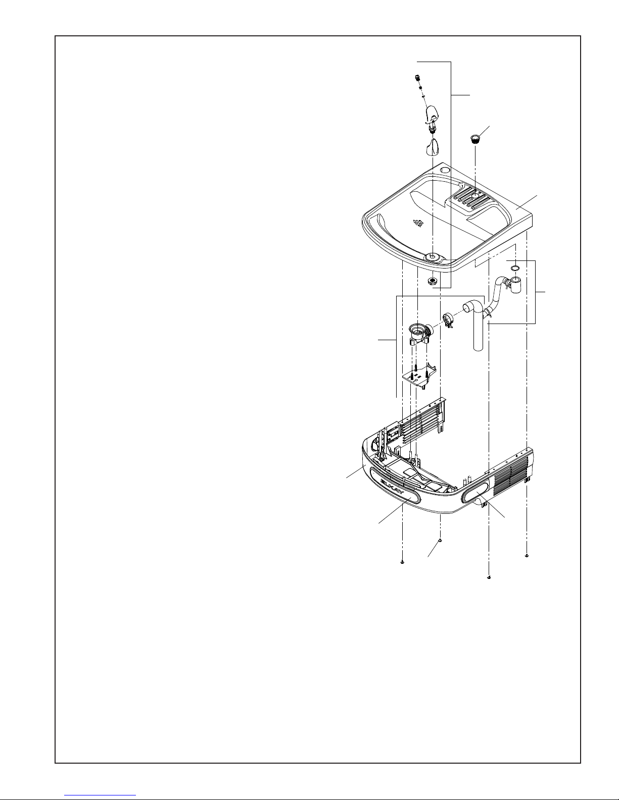
Lower and Upper Shroud
To access the refrigeration system and plumbing connections, remove four screws from bottom
of cooler to remove the lower shroud. To remove the upper shroud for access to the pushbars,
regulator, solenoid valve or other components located in the top of the unit, remove lower shroud,
disconnect drain, remove four screws from tabs along lower edge of upper shroud, unplug two wires
and water tube.
Bubbler
To remove the bubbler, rst disconnect the power supply. The underside of the bubbler can be
reached through the access panel on the underside of the upper shroud. Remove the access panel
by removing the retaining screw. To remove the bubbler, loosen locknut from the underside of the
bubbler and remove the tubing from the quick connect tting per the Operation Of Quick Connect
Fittings section in the General Instructions. After servicing, replace the access panel and retaining
screw.
Switches Behind the Push Bar
The regulator in an EZ cooler is always held fully open by the use of a
single regulator nut (See Fig. 9). Water is not dispensed until the pushbar is depressed to activate a
switch which then opens a solenoid valve. When installing the regulator nut,
the regulator spring must be depressed while turning the nut.
Single bar units will have the same wiring as side push bar units but will not have the extra leads
attached to sidebars.
To remove sidebars, from the inside compress the ared tabs and pull out carefully. To reinstall side
pushbars, the front of the pushbar is inserted rst. While keeping the switch depressed, snap the
rear of the pushbar into position.
Atienda a Instrucciones
Las cubiertas inferiores y superiores
Para obtener acceso al sistema de refrigeración y las conexiones de plomería, retire
cuatro tornillos de la parte inferior del enfriador para así poder retirar la cubierta inferior.
Para retirar la cubierta superior para obtener acceso a las barras topes de empuje,
regulador, la válvula del solenoide u otros componentes ubicados en la parte superior de la
unidad, retire la cubierta inferior, desconecte el tubo de desagüe, retire cuatro tornillos de
las lengüetas a lo largo del borde inferior de la cubierta superior, desenchufe dos cables y
la tubería de agua.
Burbujeador
Para quitar el burbujeador, primero hay que desconectar la alimentación.
Se puede obtener acceso a la parte inferior del burbujeador a través del panel de acceso en la parte
inferior de la cubierta superior. Quite el panel de acceso sacando el tornillo de retención Para retirar
el burbujeador, suelte la contratuerca de la parte inferior del burbujeador y saque la tubería del accesorio
de conexión rápida según descrito en la sección Funcionamiento de los Accesorios de Conexión Rápida en
las Instrucciones Generales. Después de realizar el servicio, reemplace el panel de acceso y el tornillo de
rretención.
Interruptores detrás de la barra tope de empuje
El enfriador EZ es parecido a un sensor fotoeléctrico en que el regulador siempre está
completamente abierto pero no surte el agua hasta que la barra tope se empuje (Figura 9).
Se escuchará un sonido de chasquidos al activar el interruptor y la válvula del solenoide.
Una sola tuerca del regulador mantiene abierto el regulador en todo momento. Al instalar la
tuerca, es necesario presionar el
resorte del regulador mientras gira la tuerca.
11
27
2
27
8
Unidades con una sola barra tendrán el mismo cableado que las unidades con barras topes
laterales pero no tendrán los cables extras conectados a las barras laterales.
Para retirar las barras laterales, desde el interior, hay que contraer las lengüetas acampanadas y retire cuidadosamente. Para reinstalar las barras topes laterales, se debe introducir la
parte frontal de las barras primero. Con el interruptor presionado, encaje con un chasquido la
parte posterior de la barra tope en la posición correcta.
Entretenir des Instructions
Enveloppes de Protection Supérieure et Inférieure
Pour accéder au système de réfrigération et aux raccords de plomberie, retirez les six vis situées
au bas du refroidisseur pour retirer l’enveloppe inférieure.
Pour retirer l’enveloppe supérieure an d’avoir accès aux boutons-poussoir, au régulateur, à
l’électrorobinet ou à tout autre composant situé au sommet de l’unité, retirez l’enveloppe inférieure, déconnectez le drain, retirez les quatre vis des pattes situées le long de l’arête inférieure
de l’enveloppe supérieure, et débranchez les deux câbles ainsi que le raccordement en eau.
Barboteur
Pour déposer le barboteur, débranchez d’abord l’alimentation électrique.
Le dessous du barboteur est accessible par le biais du panneau d’accès sur la face inférieure du
collecteur d’air. Déposez le panneau d’accès en retirant la vis de retenue.
Pour déposer le barboteur, desserrez l’écrou de blocage du dessous du barboteur et retirez la
tubulure à partir du raccord rapide conformément à la section Utilisation des raccords rapides
dans les instruction générales. Une fois le travail terminé, replacez le panneau d’accès et la vis
de
Interrupteurs derrière le bouton-poussoir
Le refroidisseur EZ a un fonctionnement similaire à celui d’un capteur photo-électrique, dans
le sens où le régleur est toujours complètement ouvert mais ne dispense de l’eau que lorsque
l’on presse le bouton-poussoir (composant 9). Un cliquetis se produit quand l’interrupteur et
l’électrorobinet se mettent en marche. Un seul écrou de régleur maintient le régleur en position
ouverte en permanence. Lors de l’installation de l’écrou, le ressort de détente doit être en
position relâchée pendant le réglage de l’écrou.
Les unités à une barre possèdent le même câblage que les unités à boutons-poussoir latéraux
mais ne possèdent pas les connections supplémentaires attachées aux barres latérales.
An de retirer les barres latérales, pressez les pattes évasées de l’intérieur et tirez doucement.
Pour réinstaller les barres latérales, la partie avant est d’abord insérée. En gardant l’interrupteur relâché, encastrez l’arrière du bouton-poussoir en position.
6
12
12
19
Fig. 3
Page 5 1000001731 (Rev. C - 01/15)
Page 6
EZSDWS*1F EZS8WS*1F, 2F 3F LZSDWS*1F, 2F, 3F LZS8WS*1F, 2F, 3F
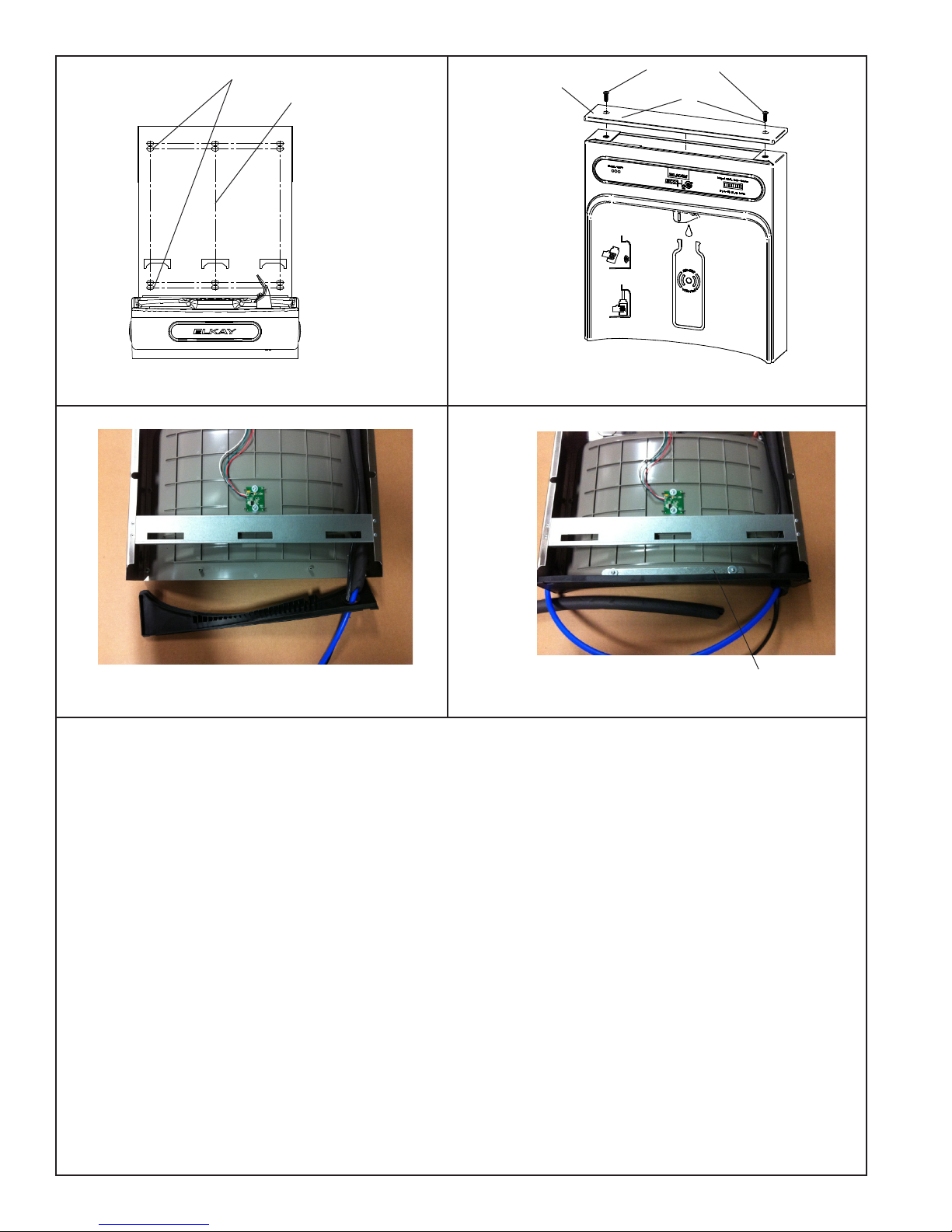
7/16” BOLT HOLES FOR
FASTENING UNIT TO WALL
UNIT CENTER LINE
TOP COVER
MOUNTING
SCREWS
29
Fig. 4 Fig. 5
Fig. 6
Fig. 7
& SCREWS
Bottle Filler Installation Instructions
1) Remove two (2) mounting screws with 5/32” Allen wrench holding top cover to Bottle Filler (See Fig. 5). Remove top cover. Note do not discard mounting
screws, they will be needed to reinstall top cover.
2) Remove wall mounting plate from Bottle Filler. Place wall plate against wall on top of basin. Center the wall plate side to side with the basin. Mark
the six (6) mounting holes with a pencil (See Fig. 2).
3) Remove wall mounting plate from wall. NOTE: Mounting plate MUST be supported securely. Add xture support carrier if wall will not provide adequate
support.
4) Install wall mounting plate to wall using six (6) 7/16” obround mounting holes (mounting bolts not included) (See Fig. 4). Use appropriate fasteners for
your wall type.
5) Feed power cord & 3/8” water line through hole in tower/basin gasket (See Fig 6).
6) Install gasket on bottom of bottle ller tower with gasket support bracket, (2) washers, & (2) screws (See Fig 7).
7) Fish the purple wire (single units) or the purple and yellow wires (two-level units) up through basin hole & hole in gasket.
8) For Single Model installations: Attach the purple wire from cooler to the purple wire on the back of the unit, (Note yellow wire is not used).
8a) For Two-Level model installations: Attach the purple and yellow wires from coolers to the purple and yellow wires on the back of the unit, purple to
purple, yellow to yellow.
9) Lay Bottle Filler on water cooler basin and cut insulation from tube even with bottom of gasket, remove this insulation from the 3/8” tube, but do not discard.
Fish the power cord and waterline through the hole on top of water cooler. NOTE: To prevent scratching the basin place a towel or soft
cloth over the entire basin when working above it.
10) With the power cord, wire(s), and waterline through hole on top of water cooler place Bottle Filler on the three (3) angled tabs protruding from the wall
mounting plate, installed on wall. Make sure round boss in gasket ts in hole of basin. (See Fig. 8).
11) Once Bottle Filler is installed on wall plate tabs, water line, wire(s) and power cord are installed properly, push top of Bottle Filler toward
wall and line up top cover two (2) holes.
12) Reinstall Top Cover on Bottle Filler (See Fig. 5) with two mounting screws from step 1 above. Caution, do not over tighten screws.
13) Install remaining tube insulation to the water line from bottle ller, connect Bottle Filler waterline inside of the water cooler by connecting the 3/8” water line to the tee.
14) Install lter cartridge, remove lter from carton, remove protective cap, attach lter to lter head by rmly inserting into head and rotating lter
clockwise. NOTE: If existing plumbing rough in locations (Drain, Water In, and Electric Supply) do not allow the lter to be mounted inside the cooler cabinet
the lter can be installed horizontally below the unit. A retrot kit is available to mount the lter beneath the cooler.
15) Turn water supply on and inspect for leaks. Fix all leaks before continuing.
16) Once unit has been inspected for leaks and any leaks found corrected, plug Bottle Filler and unit into wall. Be sure to reinstall fuse to the circuit or
switch the circuit breaker back to the “ON” position.
17) Once power is applied to Bottle Filler, the GREEN LED light should illuminate showing good lter status along with the LCD Bottle Counter.
18) Verify proper dispensing by placing cup, hand, or any opaque object in front of sensor area and verify water dispenses. Note: the rst initial dispenses
might have air in line which may cause a sputter. This will be eliminated once all air is purged from the line.
19) Once unit tests out, install Lower Panel back on water cooler(s). Units are now ready for use.
BRACKET, WASHERS,
1000001731 (Rev. C - 01/15)
Page 6
Page 7
EZSDWS*1F EZS8WS*1F, 2F, 3F LZSDWS*1F, 2F, 3F LZS8WS*1F, 2F, 3F
BF11 PROGRAM
SETTING THE CONTROL BOARD
VERIFY CONTROL BOARD SOFTWARE
1) To verify the software program of the control board the unit will
need to be shut down and restarted. The chiller (if present) does
not need to be shut down and restarted.
2) The units lower panel must be open to access the power cord and
wall outlet.
3) Shut down the unit by unplugging the power cord from the wall
outlet.
4) Restart the unit by plugging the power cord back into the wall
outlet.
5) Upon start up, the bottle count display will show the software
designation of BF11.
6) Reference the BF11 instructions for setting the control board.
ACCESSING THE PROGRAMMING BUTTON
1) To access the program button remove the top cover of the bottle-
ller. Remove the two (2) screws holding top cover to bottle ller with a 5/32” allen wrench. Remove top cover. Do not discard
mounting screws, they will be needed to reinstall the top cove after
programming operations are completed. The programming button
is located at the top right side of the unit on the control board.
RESET THE FILTER MONITOR
1) Instructions apply to ltered units only.
2) Depress the program button for approximately 2 seconds until
the display changes then release. The display will change and
scroll through two messages:
“RST FLTR” – Reset Filter Monitor
“SETTINGS” – System Settings Sub Menu
If the program button is not pushed again the display will scroll
through the two messages above for three cycles and then default
back to bottle count and be back in run mode.
3) When the display changes to “RST FLTR”, depress the button
again. The display will change to show “FLTR =”. Depress the
button again and the display will show “FLTR =0”
4) The Green LED should be illuminated indicating that the visual
lter monitor has been reset.
SETTING RANGE OF THE IR SENSOR
1) Depress the program button for approximately 2 seconds until
the display changes then release. The display will change and
scroll through two messages:
“RST FLTR” – Reset Filter Status LED
“SETTINGS” – System Settings Sub Menu
If the program button is not pushed again the display will scroll
through the two messages above for three cycles and then default
back to bottle count and be back in run mode.
2) When the display changes to “SETTINGS”, depress the button
again. The display will change to show
“RNG SET” - Range set for IR sensor.
“UNIT TYP” - Type of unit (REFRIG or NON-RFRG)
“FLT SIZE” - Select lter capacity
“RST BCNT” - Reset bottle count
3) When display shows “RNG SET” push program button once the
display will show current value (can be 1 – 10) e.g. “RNG = 3”.
4) Once display shows current value push the program button to
scroll through value of 1 – 10. Select the desired range setting.
5) Once range is selected allow approximately 4 seconds to pass and
then the display will go back to bottle counter and be in run mode.
6) Test bottle ller by placing bottle or hand in front of sensor to
make sure water is dispensed.
SETTING UNIT TYPE
1) Depress the program button for approximately 2 seconds until the
display changes then release. The display will change and scroll
through two messages:
“RST FLTR” – Reset Filter Status LED
“SETTINGS” – System Settings Sub Menu
If the program button is not pushed again the display will scroll
through the two messages above for three cycles and then default
back to bottle count and be back in run mode.
Continued from below:
2) When the display changes to “SETTINGS”, depress the button again.
The display will change to show
“RNG SET” - Range set for IR sensor.
“UNIT TYP” - Type of unit (REFRIG or NON-RFRG)
“FLT SIZE” - Select lter capacity
“RST BCNT” - Reset bottle count
3) When display shows “UNIT TYPE” push program button once the
display will show current value. Can be REFRIG or NON-RFRG
4) Push button once to change value. Once value is selected the display
will show the new value. (Can be REFRIG or NON-RFRG)
“REFRIG“ - stands for refrigerated product. In this setting the ow rate is
estimated at 1.0 gallon per minute.
“NON-RFRG“ - stands for nonrefrigerated product. In this setting the
ow rate is estimated at 1.5 gallons per minute. Both “REFRIG“ and
“NON-RFRG“ simulate 1 bottle equal to 20 oz.
5) Allow approximately 4 seconds to pass and the display will return to
bottle counter and be in run mode.
RESETTING BOTTLE COUNT
1) Depress the program button for approximately 2 seconds until the
display changes then release. The display will change and scroll
through two messages:
“RST FLTR” – Reset Filter Status LED
“SETTINGS” – System Settings Sub Menu
If the program button is not pushed again the display will scroll through
the two messages above for three cycles and then default back to bottle
count and be back in run mode.
2) When the display changes to “SETTINGS”, depress the button again.
The display will change to show:
“RNG SET”- Range set for IR sensor.
“UNIT TYP” - Type of unit (REFRIG or NON-RFRG)
“FLT SIZE” - Select lter capacity
“RST BCNT” - Reset bottle count
If the button is not pushed again the display will scroll through the four
messages above for three cycles and return to run mode.
3) When display shows “RST BCNT” push program button once the
display will show current value e.g. “0033183”.
4) Once display shows current value push the program button once more
to reset back to 0. The display will show BTLCT = 0 for approximately 2
seconds and then return to run mode showing 00000000 bottles.
5) Testing the bottle counter:
REFRIG units: Place bottle or hand in front of sensor for 9.4 seconds to
see bottle counter count 00000001,
(This is based on lling a 20 oz. bottle).
NON-RFRG units: Place bottle or hand in front of sensor for 6.25
seconds to see bottle counter count 00000001,
(This is based on lling a 20 oz bottle).
SETTING FILTER CAPACITY
1) Depress the program button for approximately 2 seconds until the
display changes then release. The display will change and scroll through
two messages:
“RST FLTR” – Reset Filter Status LED
“SETTINGS” – System Settings Sub Menu
If the program button is not pushed again the display will scroll through
the two messages above for three cycles and then default back to bottle
count and be back in run mode.
2) When the display changes to “SETTINGS”, depress the button again.
The display will change to show:
“RNG SET“- Range set for IR sensor.
“UNIT TYP“ - Type of unit (REFRIG or NON-RFRG)
“FLT SIZE” - Select lter capacity
“RST BCNT“ - Reset bottle count
If the button is not pushed again the display will scroll through the four
messages above for three cycles and return to run mode.
3) When display shows “FLT SIZE” push program button once. The display
will show current value. Can be 3000GAL or 6000GAL.
4) Push program button again to display the desired “FLT SIZE”.
5) Allow approximately 4 seconds to pass and the display will return to
bottle counter and be in run mode.
Page 7 1000001731 (Rev. C - 01/15)
Page 8
EZSDWS*1F EZS8WS*1F, 2F 3F LZSDWS*1F, 2F, 3F LZS8WS*1F, 2F, 3F
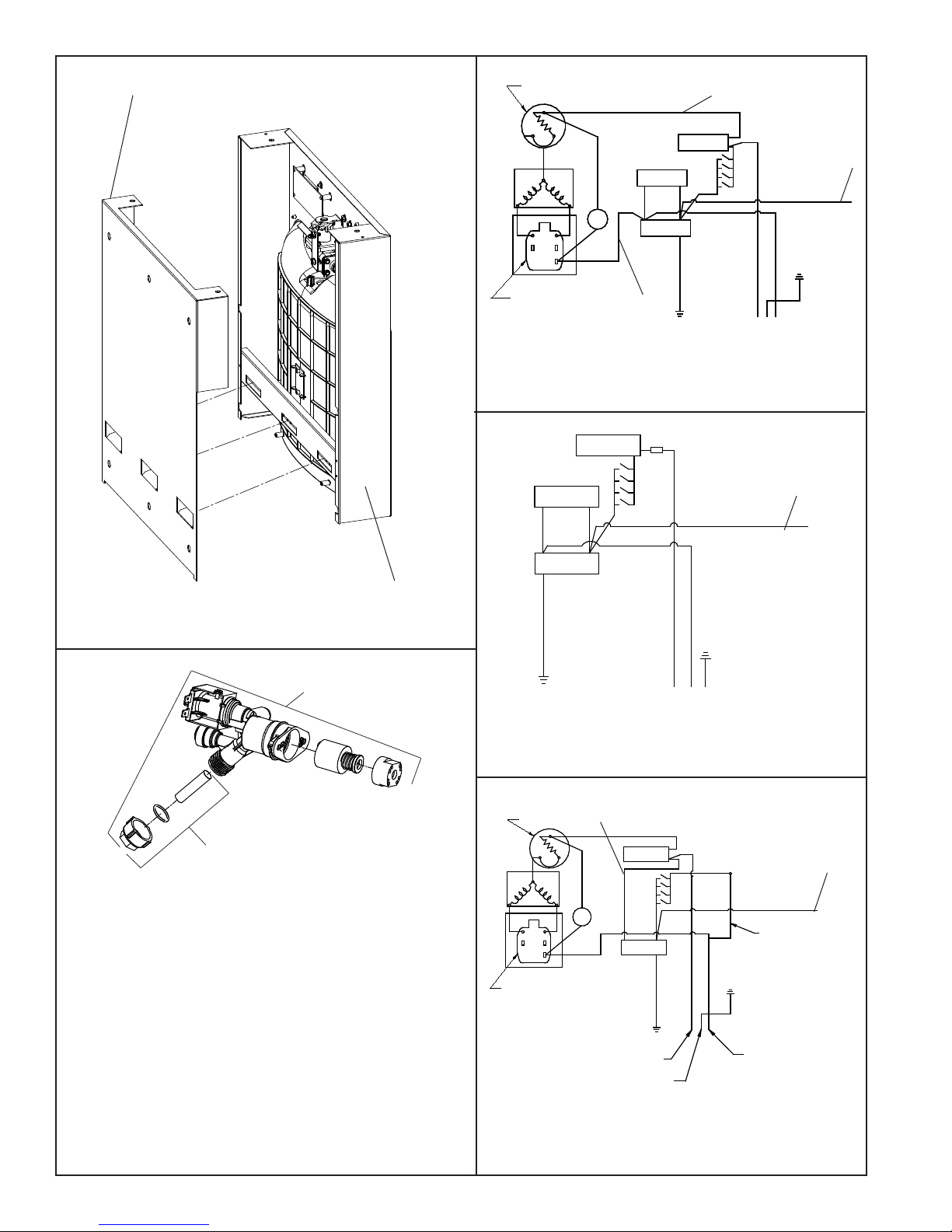
WALL MOUNTING PLATE
OVERLOAD
3
1
2
C
M
S
6
5
3
2
1
RELAY
Diagrama de Cableado Refrigerados de 115 Voltios
NOISE
SUPPRESSOR
BLK
COLD
CONTROL
NOISE
SUPPRESSOR
FAN
WHT
115V Refrigerated Wiring Diagram
Schéma Frigorique de 115 Volts
SWITCHES
14
SOLENOID
VALVE
GREEN - GND
PURPLE TO BOTTLE
14
FILLER
PURPLE TO
BOTTLE FILLER
(WHITE - N)
(BLACK - L)
Fig. 10
24
24
GND
Fig. 8
9
Cleaning the strainer
To clean the strainer, unscrew the cap of the
solenoid valve. Remove screen and rinse
thoroughly with water. Insert screen back
into solenoid valve and screw cap on. Make
sure the o-ring is placed properly.
Limpieza del ltro
Para limpiar el ltro, desatornille la tapa de
la válvula solenoide. Retire la malla y enjuague
a fondo con agua. Inserte nuevamente la
malla en la válvula solenoide y atornille la
tapa. Asegurese de que el retén anular
quede colocado correctamente.
Nettoyage du ltre
Pour nettoyer le ltre, dévisser le bouchon du
robinet électromagnétique (ou électrorobinet).
Retirez l’ écran et rincez-le á fond sous l’ eau.
Remettez l’ écran en place dans l’ électrorobinet
puis revissez le bouchon. Assurez-vous que le
joint torique est correctement positionné.
BOTTLE FILLING UNIT
10
Fig. 9
SOLENOID
VALVE
D
N
R
G
N
E
E
R
G
115V Non-Refrigerated Wiring Diagram
Diagrama de Cableado No Refrigerados de 115 Voltios
Schéma de Câblage Non Réfrigéré de 115 Volts
28
3
2
M
WHT
FAN
S
RELAY
OVERLOAD
1
C
5
263
1
COLD
CONTROL
SOLENOID
VALVE
H
T
O
O
M
S
SMOOTH
GREEN - GRND
TO "L" TERMINAL ON POWER INLET
TO "GROUND" TERMINAL
ON POWER INLET
230V Refrigerated Wiring Diagram
Diagrama de Cableado Refrigerados de 230 Voltios
Schéma Frigorique de 230 Volts
D
E
B
IB
R
GND
BOTTLE FILLER
RIBBED
GND
TO "N" TERMINAL ON
POWER INLET
Fig. 11
PURPLE TO
SHORT WHITE LEAD
FROM POWER CORD
Fig. 12
24
1000001731 (Rev. C - 01/15)
Page 8
Page 9
11
EZSDWS*1F EZS8WS*1F, 2F, 3F LZSDWS*1F, 2F, 3F LZS8WS*1F, 2F, 3F
Locknut
Tuerca de Fijación
Écrou de Blocage
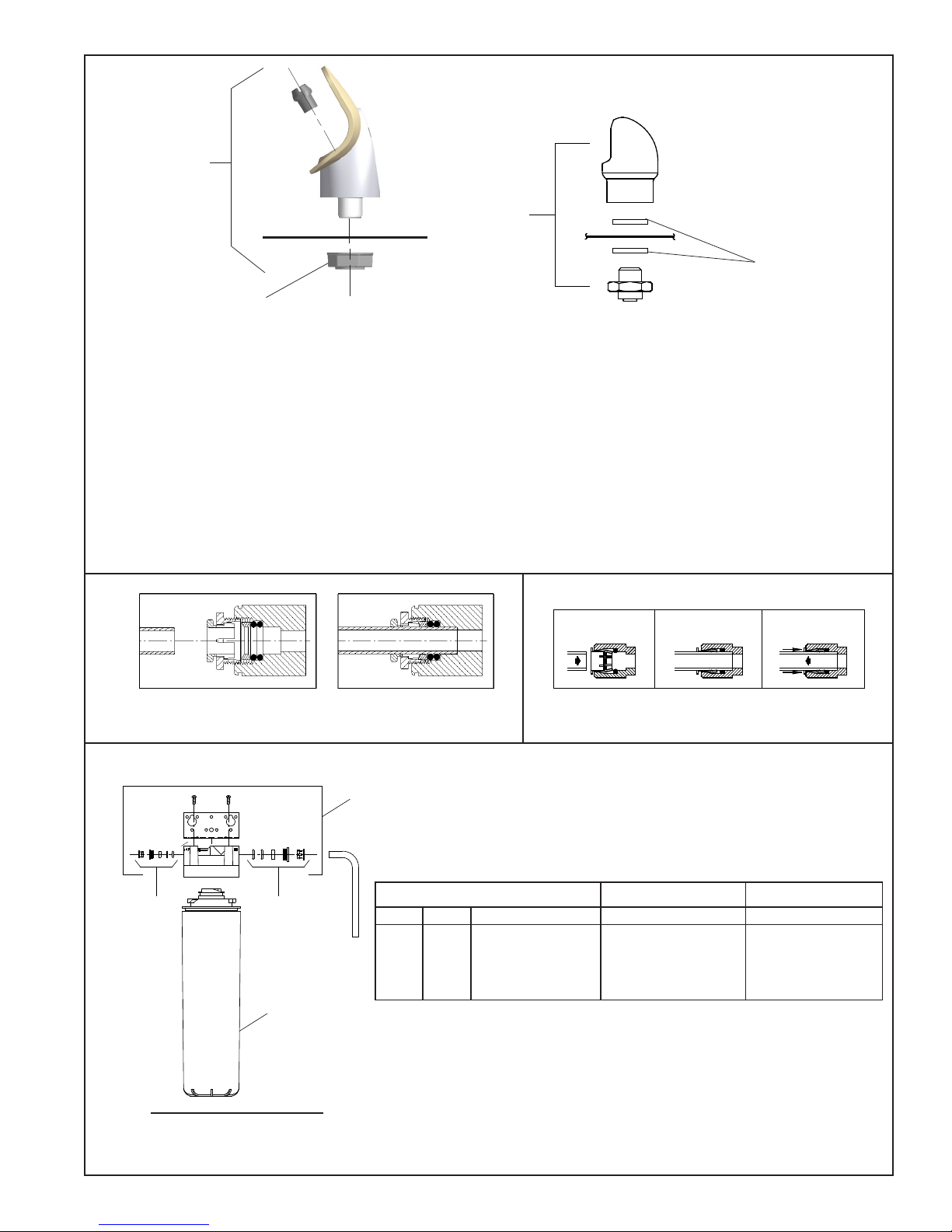
BUBBLER DETAIL
DETALLE DEL GRIFO
DETAIL DU BARBOTEUR
Fig. 13
NOTE:
When installing replacement bubbler and pedestal, tighten
nut only to hold parts snug in position. Do Not Overtighten.
NOTA:
Al instalar el grifo y pedestal de reemplazo, apriete la tuerca
unicamente para mantener las piezas en una
posicion adjustada. No dede apretarse demasiado.
REMARQUE:
Lors de L’installation du barboteur de remplacement ou du socle,
serez la vis an de maintenir les elemants en place.
Ne Pas Serrer Trop Fortement.
Basin
25
Estanque
Bassin
VANDAL RESISTANT BUBBLER DETAIL
DETALLE DEL GRIFO RESISTENTE AL VANDALISMO
DESCRIPTION DU BARBOTEUR RESISTANT AU VANDALISME
Fig. 14
OPERATION OF QUICK CONNECT FITTINGS
OPERATION OF QUICK CONNECT FITTINGS
SIMPLY PUSH IN
SIMPLY PUSH IN
TUBE TO ATTACH
TUBE TO ATTACH
TUBE IS SECURED
TUBE IS SECURED
IN POSITION
IN POSITION
26
PUSH IN COLLET
PUSH IN COLLET
TO RELEASE TUBE
TO RELEASE TUBE
Note: Screw the locknut hand tight to seal
Fig. 15
2
WATER FILTER EXPLODED VIEW
Fig. 17
A B C
Fig. 16
B CA
PUSHING TUBE IN BEFORE
PUSHING TUBE IN BEFORE
PULLING IT OUT HELPS TO
PULLING IT OUT HELPS TO
RELEASE TUBE
RELEASE TUBE
3
2
WATERSENTRY® FILTER PARTS LIST
ITEM NO. PART NO.
1
2
3
(See Fig. 17)
51300C
Filter Assy-3000 Gal.
98926C
Kit-Filter Head Fitting Includes
John Guest Fitting & 3/8”
Elbow Fitting
51469C
Assy-Filter & Bracket
includes Fltr Head/Mtg Bkt/
John Guest Ftgs/Screws
DESCRIPTION
LISTA DE PIEZAS DEL
FILTRO (Vea la Fig. 17)
DESCRIPCIÓN DESCRIPTION
Ensamblado del Filtro-3000 Galón
Montaje Cabeza Kit Filtro-Incluye
John Guest Montaje y 3/8” Codo
Conjunto del Filtro y Soporte,
Incluye Filtro Soporte/John Guest
Guarniciones/Tornillos de Montaje
de Cabeza
LISTE DES PIÈCES DU
FILTRE (Voir Fig. 17)
Ens. ltre-3000 Gallon
Raccord Tête de Filtre KitInclutJohn Guest Montage et
3/8” Raccord en Coude
Assemblêe-Filtre et Support
Inclut Filtre/Montage Support/
John Guest/Vis à Têtê
1
Page 9 1000001731 (Rev. C - 01/15)
Page 10
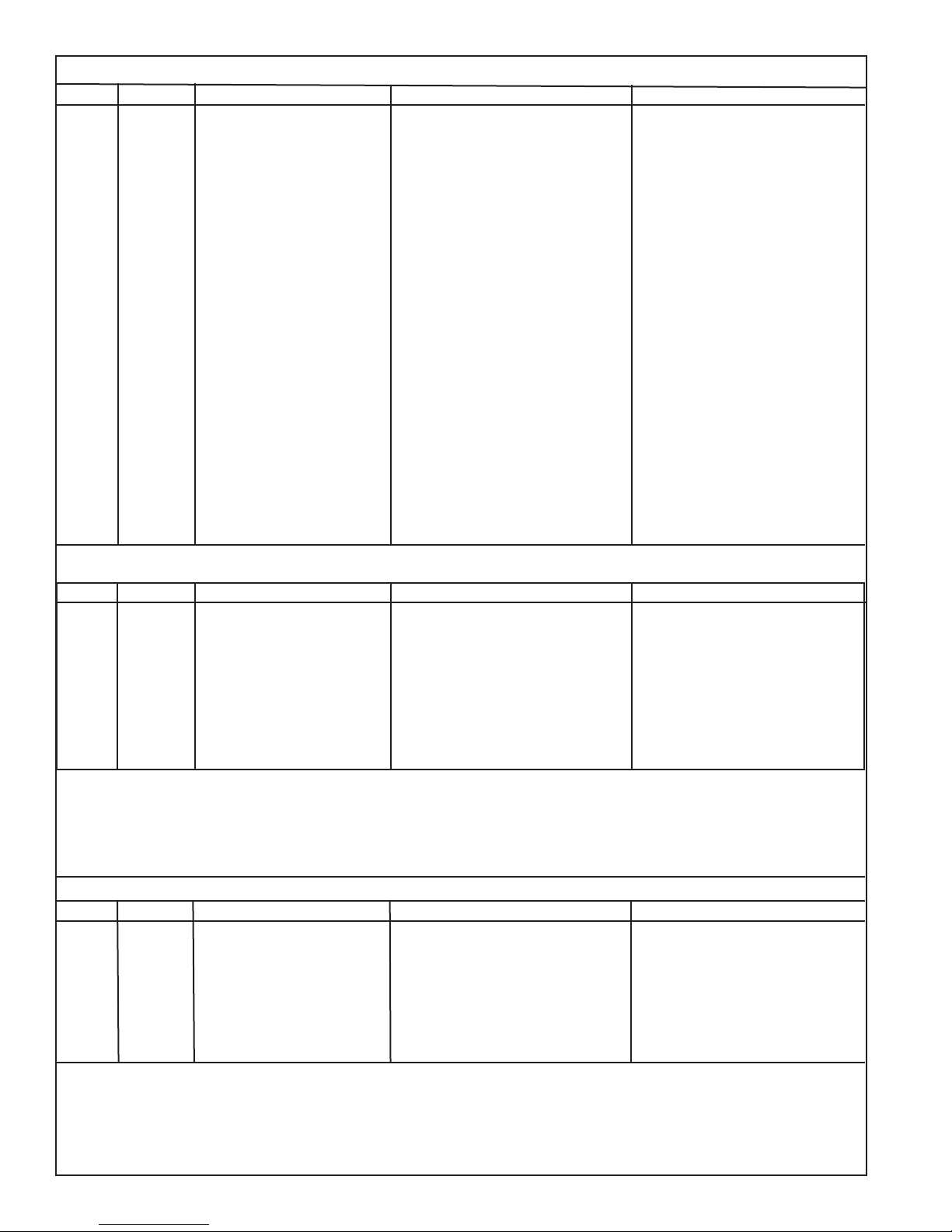
ITEM NO.
1
2
3
*4
5
6
7
8
9
10
11
12
13
14
15
16
17
18
19
20
21
22
23
24
25
26
27
NS
NS
NS
NS
NS
PART NO.
28401C
0000001337
36216C
36322C
56092C
56229C
66703C
1000001877
98169C
98466C
92715C
98734C
1000001600
98773C
98774C
98775C
98776C
98777C
98778C
98898C
0000000238
98724C
0000001144
1000001602
36299C
97446C
1000001791
1000001812
35980C
36300C
27416C
27413C
See Filter Table
EZSDWS*1F EZS8WS*1F, 2F 3F LZSDWS*1F, 2F, 3F LZS8WS*1F, 2F, 3F
115V PARTS LIST/ 115V LISTA DE PIEZAS/ 115V LISTE DES PIÈCES
DESCRIPTION DESCRIPCIÓN DESCRIPTION
Hanger Bracket
Basin - Stainless Steel
Wiring - Front/Side Push Bar
Compr - Service Pak 115V EMIS70HHR
Tube - Poly (Cut To Length)
Assy - Shroud - Upper (Front Side Push)
Kit - Drain Replacement EZ (BF)
Kit - Replacement Cap/Screen/O-Ring
Kit - Solenoid Valve/Regulator Assy
Kit - Flexi Bubbler/“O”-Ring/Nut
Kit - Pushbar (Front/Side) EZS TL
Kit - Pushbar (Front) EZS TL
Kit - Internal Wiring/Pwr Cord/Black
Kit - Fan Motor Assy/Blade/Mtr/
Kit- Compr Mtg Hdwe/Grommets/
Kit - Elect/Relay/Overload/Cover
Kit - 75583C Elbow 5/16” x 1/4”
Kit - VR Bubbler Nipple W/Gasket
Water Filter Kit (When Provided)
Drier
(Brkt, Tube, Ftg, Clamp)
Kit - Cold Control/Screws
and White Jumper Wires
Shroud/Screws/Nut
Kit - Condenser/Drier
Clips/Studs
Kit - Heatx/Drier
Kit - Hardware (EZ)
Kit - Evaporator Assembly
Tee - 1/4” x 1/4” x 3/8”
Jumper Wire (Purple)
Kit - VR Bubbler Short
Kit - Bottle Filler Drain (EZ)
Power Cord Non-Refrigerated
Jumper Wire (Yellow)
Wrapper - Stainless
Wrapper - Light Grey
Barra de Empuje de Cableado-Frontal/Lateral
Compresor Paquete de Servicio 115V EMIS70HHR
Tubería de Polietileno (Corte a la Longitud)
Cubierta - Superior (Frontal Lateral Presión)
Kit - Reemplazo de Drenaje (EZ)/Soporte/Tubo/Guar-
Kit del Reemplazo Tapa/Malla/Reten Anular
Kit - Montaje del Regulador/Válvula Solenoide
Kit - Ventilador Motor Montaje/Hoja/Motor/
Kit - Matériel de Montaje Compresor/Ojal/
Kit - de Drenaje de Llenada de la Botella (EZ)
Soporte Colgante
Estanque - Acero Inoxidable
Secador
nición de Tubo/Abrazadera
Kit - Flexi Borboteador/Oring/Teurca
Kit - Manillar (Frontal/Lateral) EZS TL
Kit - Manillar (Frontal) EZS TL
Kit - Control del Enfriamiento/Tornillo
Kit - Cableado Interno/Cable/
Negro Y Blanco Puente
Cubierta/Tornillos/Tuerca
Kit - Condensador/Secador
Kit - Intercambiador Térmico/Secador
Kit de Filtro de Agua (Cuando Provisto)
Pinza/Taquete
Kit - Juego de Accesorios (EZ)
Kit - Relé/Sobrecarga/Cubierta
Montaje del Kit-Evaporador
Tee - 1/4” x 1/4” x 3/8”
Kit - 75583C Elbow 5/16” x 1/4”
Cable - Puente (Púrpura)
Kit - VR Borboteador Corto
Kit - VR Borboteador Boquilla/Junta
Cable eléctrico L/R
Cable - Puente (Amarillo)
Envoltura - Acero inoxidable
Envoltura - Gris claro
Barre Anti-Panique Câblage Avant/Côté
Kit d’Entretien du Compresseur 115V EMIS70HHR
Tubes - Polyéthylène (Couper à la Longueur)
Enveloppe de Protection - Supérieure (Face Laterel
Kit - Remplacement de Drain (EZ)/Support/Tube/
Raccord de Tube/Bride Pour Tuyau
Kit De Rechange De Bouchon/Ecran/Joint Torique
Kit - Solénoide de la Vanne/Régulateur
Kit - Flexi Barboteur/Oring/Noix
Kit - Barre de Poussée (Avant/Côté) EZS TL
Kit - Barre de Poussée (Avant) EZS TL
Kit - Contrôle de Refroidissement/Vis
Kit - Câblage Interne/Câble d’Alimentation/Noir et
Fils de Raccordement Blanc
Kit - Ventilateur Moteur Assemblée/Lame/Moteur/
Kit - Montage du Compresseur materiel/Joint
Kit - Echangeur Thermique/Déshydrateur
Kit - Relais/Surcharge/Relais Coiffe
Assemblée de L’évaporateur en Kit
Kit - 75583C Elbow 5/16” x 1/4”
Câble - Cavalier (Pourpre)
Kit - VR Barboteur Nipple/Joint
Kit - de Remplissage de Bouteille de Vidange
Cordon d’Alimentation L/R
Kit de Filtrage d’Eau (Si Fourni)
Support de Suspension
Basin - Inox
Poussoir) Déshydrateur
Cache/Vis/Ecrou
Kit - Condenseur/Séchoir
d’étanchéité/Clip/Goujon
Kit - De Visserie (EZ)
Tee - 1/4” x 1/4” x 3/8”
Kit - VR Barboteur Court
Câble - Cavalier (Jaune)
Couvre-joint - Inox
Couvre-joint - Gris Clair
220V PARTS LIST/ 220V LISTA DE PIEZAS/ 220V LISTE DES PIÈCES
ITEM NO.
NS
NS
NS
NS
NS
PART NO. DESCRIPTION DESCRIPCIÓN DESCRIPTION
1000002147
*4
1000002146
0000000802
10
15
20
28
31431C
98751C
98752C
36004C
36066C
36067C
28030C
35826C
36300C
*INCLUDES RELAY & OVERLOAD. IF UNDER WARRANTY, REPLACE WITH SAME COMPRESSOR USED
IN ORIGINAL ASSEMBLY.
NOTE: All correspondence pertaining to any of the above
water coolers or orders for repair parts MUST include
Model No. and Serial No. of cooler, name and part number
of replacement part.
Compressor Serv. Pak (220v/50Hz)
Compressor Serv. Pak (220v/60Hz)
Kit - Solenoid Valve/Regulator Assy
Kit - Fan Motor Assy/Blade/Mtr/
Kit - Relay/Overload/Cover (220v/50Hz)
Kit - Relay/Overload/Cover (220v/60Hz)
Internal Power Cord Non-Refrigerated
Screws/Nut
Wire - Jumper (White)
Internal Power Cord
Brkt - Power Inlet
Inlet Power
Jumper Wire (Yellow)
Compresor Paquete de servicio (220v/50Hz)
Compresor Paquete de servicio (220v/60Hz)
Kit - Montaje del Regulador/Válvula Solenoide
Kit - Ventilador Motor Montaje/Hoja/Motor/
Kit - Relé/Sobrecarga/Cubierta (220v/50Hz )
Kit - Relé/Sobrecarga/Cubierta (220v/60Hz)
*INCLUYE RELÉ Y SOBRECARGA. SI ESTÁ BAJO GARANTÍA,
REEMPLACE CON EL MISMO COMPRESOR USADO EN EL
ENSAMBLADO INICIAL.
NOTA: Toda la correspondencia relacionada con el enfriador de
agua anterior o con una orden de reparación piezas DEBERÁ incluir
el número de modelo y número de serie del enfriador, el nombre y
número de pieza de la pieza de repuesto.
Tornillos/Tuerca
Cable - Puente (Blanco)
Cable de alimentación interno
Cable de alimentación interno L/R
Soporte - Entrada De Eléctric
Entrada De Eléctrico
Cable - Puente (Amarillo)
*COMPREND RELAIS ET SURCHARGE. SI SOUS GARANTIE, REMPLACEZ AVEC LE MÊME SURPRESSEUR QUE CELUI UTILISÉ
ORIGINALEMENT.
NOTE: Toute correspondance au sujet des refroidisseurs d’eau courante ou
toute commande de pièce de rechange DOIT inclure le numéro de modèle
et le numéro de série du refroidisseur ainsi que le nom et le numéro de
pièce à remplacer.
Kit d’Entretien du Compresseur (220v/50Hz)
Kit d’Entretien du Compresseur (220v/60Hz)
Kit - Solénoide de la Vanne/Régulateur
Kit - Ventilateur Moteur Assemblée/Lame/Moteur/
Kit - Relais/Surcharge/Relais Coiffe (220v/50Hz)
Kit - /Relais/Surcharge/Relais Coiffe (220v/60Hz)
Cordon d’Alimentation interne
Cordon d’Alimentation interne L/R
Support - Entrée d’alimentation
Vis/Ecrou
Câble - Cavalier (Blanc)
Entrée d’alimentation
Câble - Cavalier (Jaune)
BOTTLE FILLER REPLACEMENT PART KITS
ITEM NO. PART NO. DESCRIPTION DESCRIPCIÓN DESCRIPTION
NS
NS
NS
NS
NS
NS
NS
NS
NS
29
98543C
98544C
98545C
98632C
98546C
98547C
98549C
98551C
98552C
1000001813
Kit - Electrical Package
Kit - IR Sensor
Kit - BF Solenoid Valve Replacement 115V
Kit - BF Solenoid Valve Replacement 230V
Kit - Aerator Replacement
Kit - Top Cover Replacement
Kit - Hardware & Waterway Parts
Kit - Filter Mounting Cover
Kit - Retro Filter Mounting
Kit - Tower/Basin Gasket
Paquete Kit - Eléctrico
Sensor Kit - IR
Reemplazo de la Válvula de Solenoide Kit 115V
Reemplazo de la Válvula de Solenoide Kit 230V
Reemplazo Kit - Aireador
Kit - Tapa Cubierta Reemplazo
Piezas del Kit - De Hardware y Por Vía Navegable
Cubierta del Filtro de Kit - De Montaje
Montaje de Filtro Kit - Retro
Kit - Torre/Cuenca Junta
Forfait Kit - Electriqueso
Kit - Rcepteur IR
Remplacement de la Valve Solénoïde - Kit 115V
Remplacement de la Valve Solénoïde - Kit 230V
Remplacement du Kit - Aérateur
Remplacement du Kit - Top Couvercle
Pièces Kit - Matériel et Voie Navigable
Couvercle de Filtre - Kit Montage
Montage de Retro - Kit Filtre
Kit - Tour/Collecteur
REPAIR SERVICE INFORMATION TOLL FREE NUMBER 1.800.260.6640
INFORMATIONS POUR LE SERVICE PAR NUMERO SANS FRAIS 1.800.260.6640
FOR PARTS, CONTACT YOUR LOCAL DISTRIBUTOR OR CALL 1.800.834.4816
PARA PIEZAS, CONTACTE A SU DISTRIBUIDOR LOCAL O LLAME AL 1.800.834.4816
PRINTED IN U.S.A.
IMPRESO EN LOS E.E.U.U.
IMPRIMÉ AUX É.-U.
POUR OBTENIR DES PIÈCES, CONTACTEZ VOTRE DISTRIBUTEUR LOCAL OU COMPOSEZ LE 1.800.834.4816
ELKAY MANUFACTURING COMPANY • 2222 CAMDEN COURT • OAK BROOK, IL 60523 • 630.574.8484
1000001731 (Rev. C - 01/15)
NÚMERO GRATIS DE SERVICIO 1.800.260.6640
Page 10
 Loading...