

Elkay ESRC8 1E Series, ESRC13 1E Series, ESRC13 2E Series, ESRC13 3E Series Installation, Care & Use Manual
Page 1
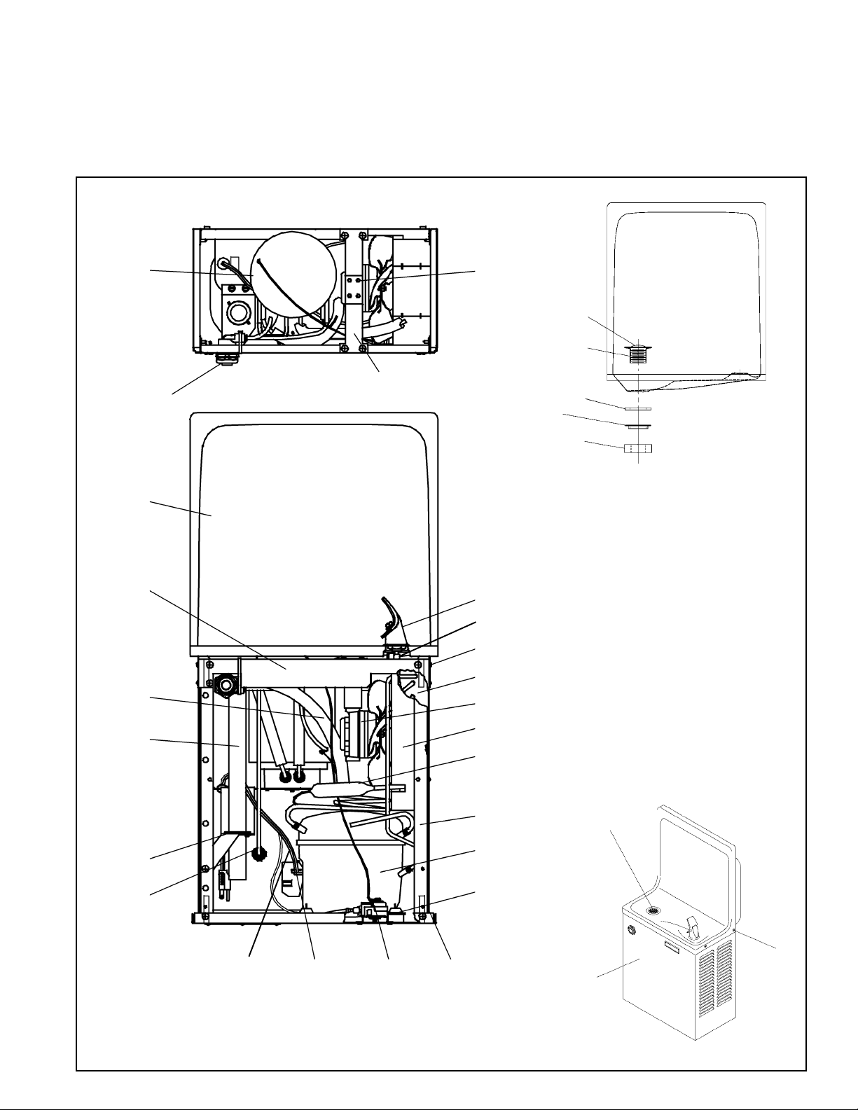
ESRC8*1E ESRC13*1E, 2E,3E
®
With FLEXI-GUARD
Installation/Care/Use Manual
USES HFC-134A REFRIGERANT
28
SEE FIG. 3
25
44
22
6
38
39
2
24
45
40
8 - See Fig. 4
46
42
13
3, 4, 5
23
30
29
7
14
SEE DETAIL
41
18
15, 16
& 17
1
2719, 20, 21
43
FIG. 1
PAGE 1
ABOVE
26
37
97377C (Rev. D - 8/01)
Page 2
MOUNTING
BOX
ESRC8*1E ESRC13*1E, 2E, 3E
POSITION FASTENING
CLIP AS SHOWN AFTER
COOLER IS HUNG IN
PLACE
SHIPPING POSITION
OF FASTENING CLIP
COOLER BASE
DECREASE HEIGHT FOR CHILDREN.
REDUZCA PARA LOS NIÑOS.
ADULTES. INSTALLEZ PLUS BAS POUR
* RECOMMENDED HEIGHT FOR ADULTS.
LES ENFANTS.
* ALTURA RECOMENDADA PARA ADULTOS.
* HAUTEUR RECOMMANDÉE POUR LES
DETAIL A
DETAIL B
SEE DETAILS
A & B
FINISHED FLOOR
PISO ACABADO
PLANCHER FINI
UBICACIÓN DE LA TOMA DE ELECTRICIDAD
EMPLACEMENT DE LA PRISE DE COURANT
ASEGURE UNA VENTILACIÓN ADECUADA MANTENIENDO UN ESPACIO E 4" (102mm) (MÍN.)
DE HOLGURA ENTRE LA REJILLA DE VENTILACIÓN DEL MUEBLE Y LA PARED
ASSUREZ-VOUS UNE BONNE VENTILATION EN GARDANT 4" (102mm) (MIN.)
ENTRE LES ÉVENTS DE LENCEINTE ET LE MUR.
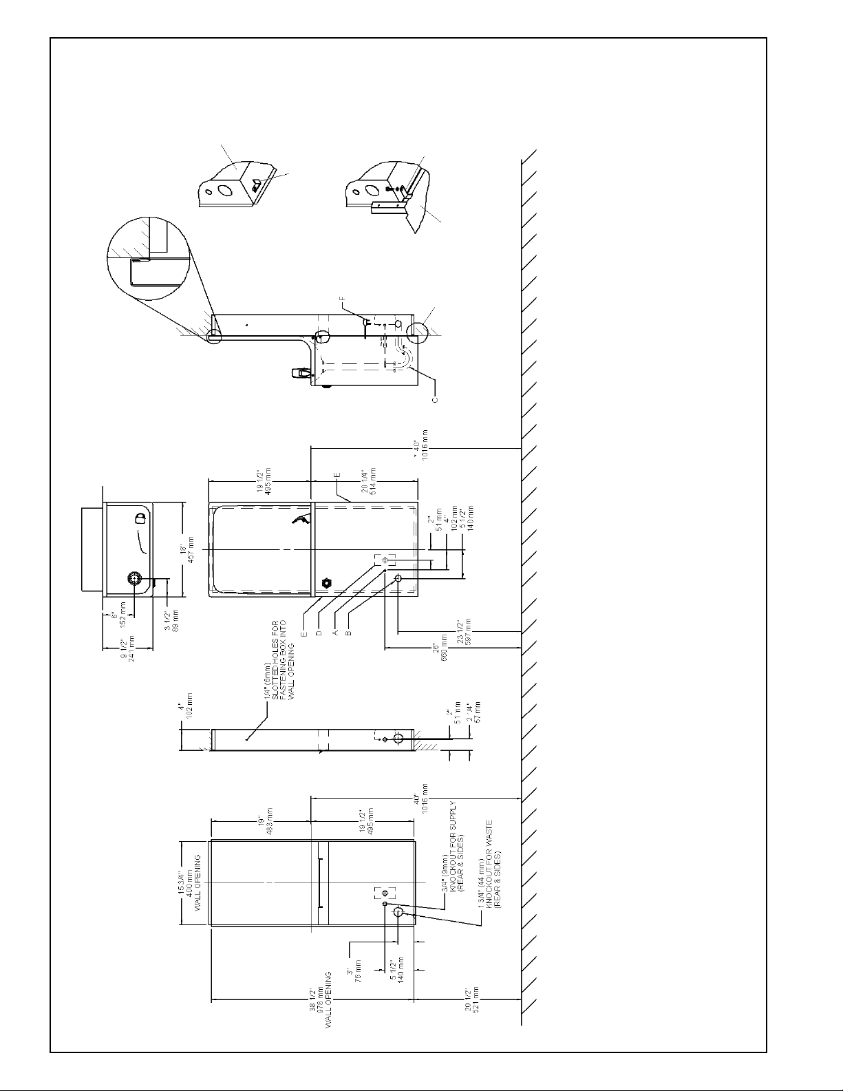
D = ELECTRICAL OUTLET LOCATION
E = INSURE PROPER VENTILATION BY MAINTAINING 4" (102mm) (MIN.) CLEARANCE
FROM CABINET LOUVERS TO WALL.
FIG. 2
CABLE ELÉCTRICO DE 1½ PIE, 457 mm DE LARGO
CORDON DALIMENTATION 1-1/2' (457mm)
F = POWER CORD 1-1/2FEET (457mm) LONG
ROUGH-IN
MOUNTING BOX
97377C (Rev. D - 8/01)
PAGE 2
(38 mm) FUERA DE LA LLAVE DE PASO EN LA PARED COLOCADA POR TERCEROS.
CONNECTANT UNE TUYAUTERIE DE 1-1/2 PO. (38 mm) DEPUIS LE ROBINET D'ARRÊT FOURNI PAR D'AUTRES.
UBICACIÓN RECOMENDADA PARA EL DRENAJE DE SALIDA DE AGUA, DE 1¼ DE DIÁMETRO.
EMPLACEMENT RECOMMANDÉ POUR LE DRAIN DE D.E. 1-1/4" DE SORTIE DEAU.
FROM WALL SHUT OFF BY OTHERS
SE RECOMIENDA UBICAR EL TUBO CORTO DE CONEXIÓN AL TUBO DE COBRE SIN CHAPAR DE 3/8" DE DIÁM. EXT. A 1-1/2"
LEGEND/LEYENDA/LÉGENDE
A = RECOMMENDED WATER SUPPLY LOCATION 3/8 O.D. UNPLATED COPPER TUBE CONNECT STUB 1-1/2 IN. (38 mm) OUT
EMPLACEMENT RECOMMANDÉ D'ALIMENTATION EN EAU PAR TUBE EN CUIVRE NON PLAQUÉ DE 3/8 PO. (9,5 mm) D.E.
PURGADOR DE 1¼ NO PROPORCIONADO**
B = RECOMMENDED LOCATION FOR WASTE OUTLET 1-1/4 O.D. DRAIN
C = 1-1/4 TRAP NOT FURNISHED**
SIPHON 1-1/4 NON FOURNI**
Page 3
ESRC8*1E ESRC13*1E, 2E,3E
IMPORTANT
ALL SERVICE TO BE PERFORMED BY AN AUTHORIZED SERVICE PERSON
HANGER BRACKETS AND TRAP INSTALLATION
1) Remove hanger brackets fastened to back of cooler by removing screws.
2) Mount the hanger brackets and trap as shown in Figure 2.
NOTE: Hanger brackets and trap MUST be supported securely. Add fixture support carrier if wall will not provide adequate support.
IMPORTANT:
5-1/2 in. (140mm) dimension from wall to centerline of trap must be maintained for proper fit.
Anchor hanger securely to wall using all six (6) 1/4 in. dia. mounting holes.
3) Install straight valve for 3/8 in. O.D. unplated copper tube.
INSTALLATION OF COOLER
4) Hang the cooler on the hanger brackets. Be certain the hanger brackets are engaged properly in the frame and wrapper.
5) Remove the access panel on the underside of the cooler and set it aside.
6) Connect water inlet line--See Note 4 of General Instructions.
7) Remove the slip nut and gasket from the trap and install them on the cooler waste line making sure that the end of the waste line fits into the
trap. Assemble the slip nut and gasket to the trap and tighten securely.
8) Replace the front panel and secure by retightening all screws.
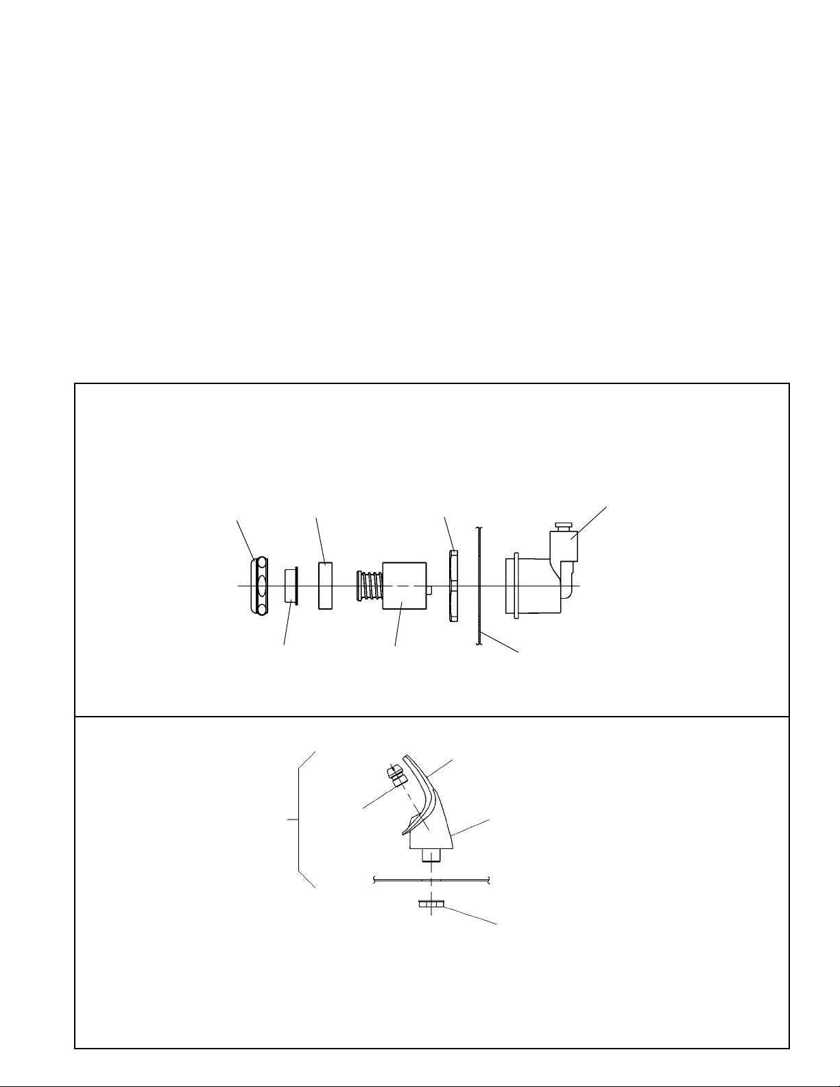
Stream height is factory set at 35 PSI. If supply pressure varies greatly
from this, remove items 31 and 32 and adjust screw on item 34. Clockwise
adjustment will raise stream and counter-clockwise adjustment will lower
stream. For best adjustment, stream should hit basin approximately 6-1/2"
(165mm) from bubbler.
31
33
Also See General Instructions
32
START UP
34
FIG. 3
35
36
WRAPPER
10
8
NOTE:
WHEN INSTALLING REPLACEMENT BUBBLER
AND PEDESTAL, TIGHTEN NUT (ITEM 12) ONLY
TO HOLD PARTS SNUG IN POSITION.
DO NOT OVER TIGHTEN.
9
FIG. 4
PAGE 3
11
BASIN
12
97377C (Rev. D - 8/01)
Page 4
ITEM NO. PART NO.
1
2
3
4
5
6
7
8
9
10
11
12
13
14
15
16
17
18*
19
20
21
22
23
24
25
26
27
28
29
30
31
32
33
34
35
36
37
38
39
40
41
42
43
44
45
46
31517C
27321C
30699C
70018C
31490C
70009C
50186C
51349C
40322C
50934C
50168C
75580C
62152C
66202C
50144C
70184C
70418C
35960C
35958C
35768C
35959C
66501C
40041C
40429C
50074C
20593C
70208C
31513C
66505C
55996C
27239C
40089C
40048C
15005C
61313C
40169C
50986C
See Color Table
40038C
40619C
50105C
27093C
27292C
27331C
27094C
40043C
70817C
ESRC8*1E ESRC13*1E, 2E, 3E
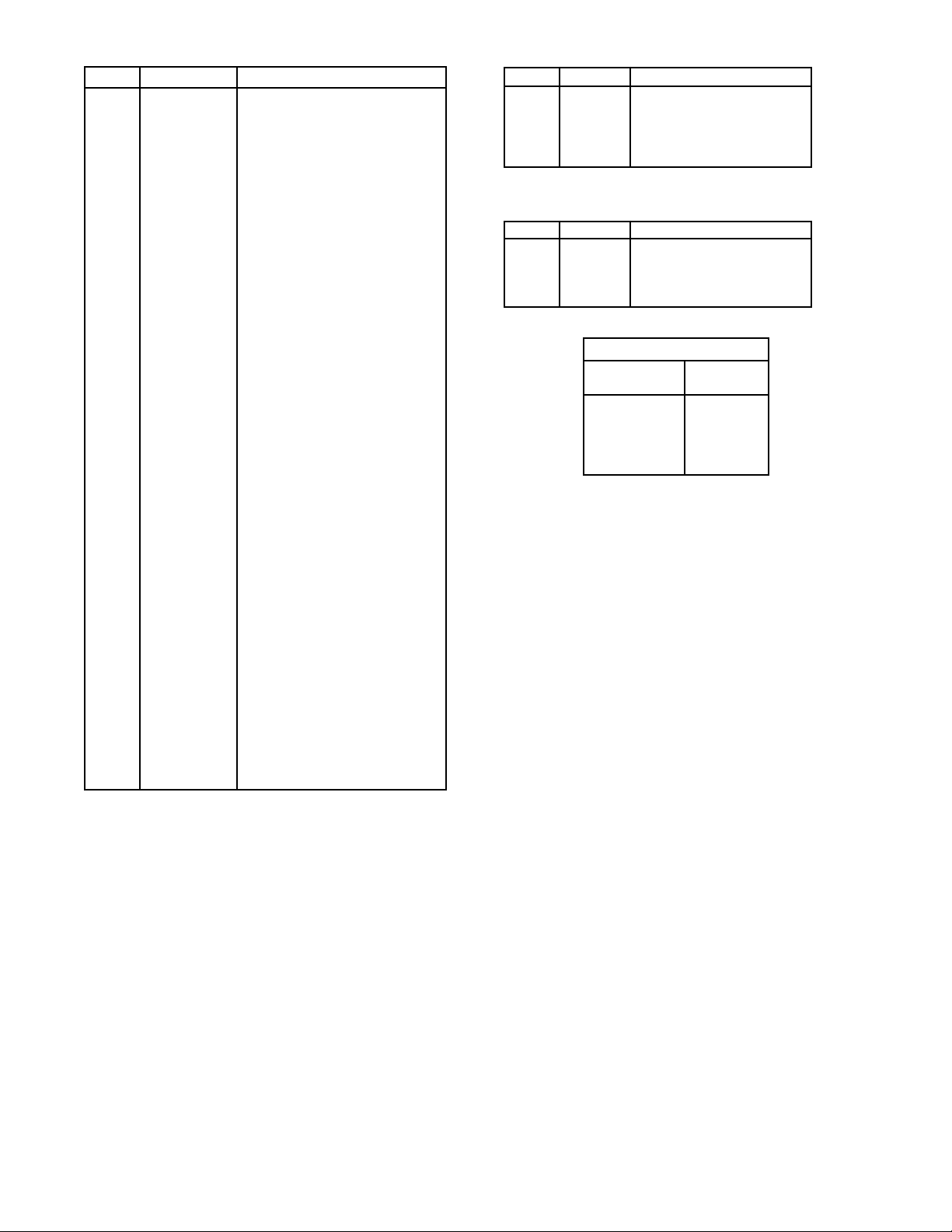
PARTS LIST
DESCRIPTION
Power Cord
Fan Bracket
Fan Blade
Hex Nut - Fan Blade
Fan Motor
Screw (Fan Motor)
Shroud - Fan
Bubbler Assy
Orifice Assy
Housing Assy
Pedestal
Locknut
Condenser
Drier
Grommet - Compressor Mtg.
Hair Pin - Cotter
Washer
Compressor Serv. Pak EM65
Overload
Cover - Relay
Relay
Heat Exchanger
Tailpipe Assy (8 Gal)
Precooler Assy (13 Gal)
Tailpipe Gasket
Basin - Stainless Steel
Screw - Basin Mtg.
Cold Control
Evaporator Assembly
Strainer
Bracket - Precooler
Cover
Button
Retaining Nut
Regulator
Hex Nut
Regulator Holder
Wrapper
Strainer - Beehive
Ferrule - Tailpipe
Tailpipe Gasket
Angle-Front Corner
Bracket-Basin Mounting
Frame-Back/Bottom
Bracket-Front
Locknut
Fitting - Elbow 1/4 Stem
1
5
18*
19
22
1
5
18*
22
PART. NO. DESCRIPTIONITEM NO.
31506C
31430C
35763C
31024C
66552C
PART. NO. DESCRIPTIONITEM NO.
31506C
31431C
35842C
66223C
PANEL COLOR
Gray Beige
Almond
Stainless Steel
Sandalwood
Granite
220/240V 50Hz
Power Cord
Fan Motor
Compressor Serv. Pak
Overload/Relay Assy.
Heat Exchanger
220/240V 60Hz
Power Cord
Fan Motor
Compressor Serv. Pak
Heat Exchanger
COLOR TABLE
Item No. 37
Part No.
21017C
21481C
21013C
21480C
27208C
*INCLUDES RELAY & OVERLOAD. IF UNDER WARRANTY,
REPLACE WITH SAME COMPRESSOR USED IN ORIGINAL
ASSEMBLY.
NOTE: All correspondence pertaining to any of the above
water coolers or orders for repair parts MUST include Model
No. and Serial No. of cooler, name and part number of replacement part.
www.DrinkingFountainDoctor.com 800-518-5388
PRINTED IN U.S.A.
ELKAY MANUFACTURING COMPANY 2222 CAMDEN COURT OAK BROOK, IL
97377C (Rev. D - 8/01)
PAGE 4
 Loading...