

ERO8C*C
Installation/Care/Use Manual
Soft Sides™ Refrigerated Fountain with FLEXI-GUARD
12
SEE FIG. 4
31
14
31
®
Installer
T o assure you install this model easily and correctly ,
PLEASE READ THESE SIMPLE INSTRUCTIONS BEFORE ST ARTING THE
INST ALLATION. CHECK YOUR INST ALLA TION FOR COMPLIANCE WITH
PLUMBING , ELECTRICAL AND OTHER APPLICABLE CODES. After installation, leave
these instructions inside the fountain for future reference.
IMPORTANT
ALL SERVICE TO BE PERFORMED BY AN AUTHORIZED SERVICE PERSON
IMPORTANT! INSTALLER PLEASE NOTE.
THE GROUNDING OF ELECTRICAL EQUIPMENT SUCH AS TELEPHONE, COMPUTERS, ETC. TO
WA TER LINES IS A COMMON PROCEDURE. THIS GROUNDING MA Y BE IN THE BUILDING OR MA Y
OCCUR A WA Y FROM THE BUILDING . THIS GROUNDING CAN CAUSE ELECTRICAL FEEDBACK
INTO A FOUNT AIN, CREA TING AN ELECTROL YSIS WHICH CAUSES A MET ALLIC T ASTE OR AN
INCREASE IN THE METAL CONTENT OF THE WATER. THIS CONDITION IS A VOIDABLE BY USING
THE PROPER MA TERIALS AS INDICA TED. ANY DRAIN FITTINGS PROVIDED BY THE INST ALLER
SHOULD BE MADE OF PLASTIC TO ELECTRICALL Y ISOLA TE THE FOUNT AIN FROM THE BUILDING
PLUMBING SYSTEM.
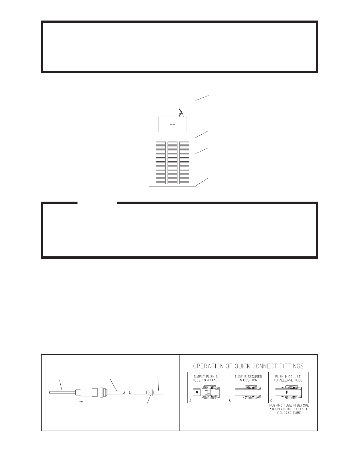
1/4" O.D. TUBE
WATER INLET
TO COOLER
3/8" O.D. UNPLATED
COPPER TUBE CONNECT
COLD WATER SUPPLY
NOTE: WATER FLOW
DIRECTION
BUILDING WATER
INLET
SERVICE STOP
(NOT FURNISHED)
FIG. 2FIG. 1
97873C (Rev. E - 8/07)
ERO8C*C
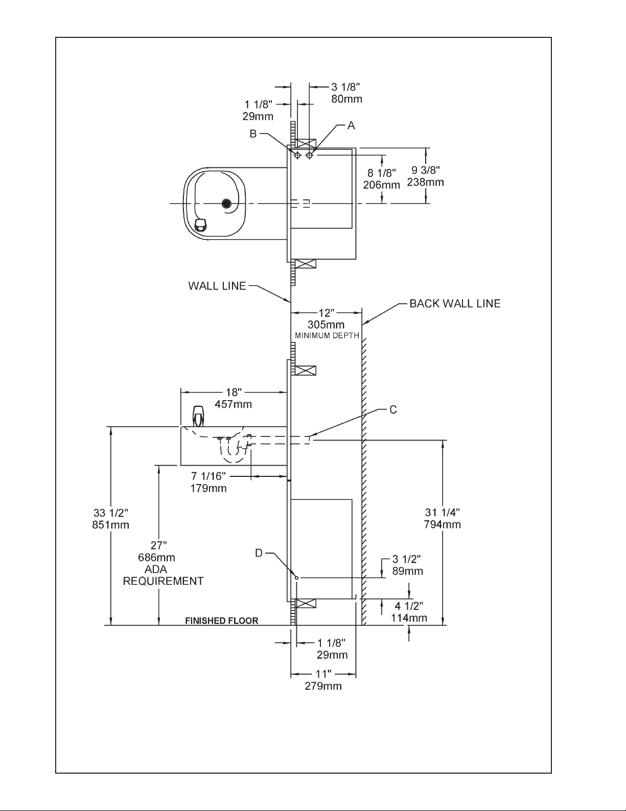
ERO8C ROUGH-IN
LEGEND
A = 1/4" O.D. TUBE CONNECT (CHILLER W A TER OUTLET)
B = 3/8" O.D. TUBE CONNECT (CHILLER WA TER INLET) SHUT OFF V AL VE BY OTHERS
C = 1-1/4" TRAP FURNISHED
D = ELECTRICAL INLET
FIG. 3
97873C (Rev. E - 8/07)
PAGE 2

ERO8C*C
INSTALLATION INSTRUCTIONS
1. Install mounting frame. See mounting frame instructions.
2. Install remote chiller. Remove front panel of chiller. Slide chiller onto the shelf and position it to the left within the guides on the shelf.
3. Attach solenoid valve assy to the underside of cross member of mounting frame. See Figure 7.
4. Make water supply connections. Install a shut-off valve and union connection to building water supply (valve and union not provided). Turn on the
water supply and flush the line thoroughly.
5. Make connection between remote chiller and building supply line. Install the strainer on the chiller inlet tube. Install a 3/8" O.D. unplated copper water
line between the valve and the cooler. Remove all burrs from the outside of the water line. Insert the 3/8" water line into the inlet side of the strainer
by pushing it in until it reaches a positive stop, approximately 3/4" (19mm). See Figures 2 and 5. DO NOT SOLDER TUBES INSERTED INTO THE
STRAINER AS DAMAGE TO THE O-RINGS MAY RESUL T. Inst all the 1/4" x 1/4" union (provided) on the chiller outlet tube.
6. Make connection between remote chiller and solenoid valve assy. Insert end of 1/4" O.D. poly tubing (provided) into union on chiller outlet and the
other end into straight fitting on solenoid valve assy.
7. Hang the upper panel on the mounting frame hanger. Align holes in the panel with holes in the mounting frame. Be sure that panel is engaged with
hanger at top of frame before releasing it.
8. Install fountain. Remove bottom cover plate on underside of fountain and save the screws. Mount the fountain to the upper panel and the wall frame
with (4) 5/16" x 3/4" (19mm) long bolts and nuts (provided). Tighten securely.
9. Connect solenoid valve assy and regulator holder in fountain by inserting 1/4" O.D. poly tubing (provided).
10. Remove elbow from end of p-trap and attach it to drain tube. Re-attach elbow to p-trap and cut waste tube to required length using plumbing
hardware and trap as a guide.
11. Connect power cord of sensor to solenoid valve by running it through the back panel and connecting it as shown in Fig. 8. Connectors may be
connected to either terminal on solenoid valve. Attach ground wire to solenoid valve bracket with green ground screw.
12. Turn on water supply. Release air from tank by interrupting infrared beam; steady stream of water assures all air is removed. The sensor has a 30
second maximum ON time. It may be necessary to step away from beam a few times to allow chiller tank to refill. Check for leaks.
13. These products are designed to operate on 20-105 PSIG supply line pressure. If inlet pressure is above 105 PSIG, a pressure regulator must be
installed in the supply line. Any damage caused by reason of connecting these products to supply line pressures lower than 20 PSIG or higher than
105 PSIG is not covered by warranty.
14. Make electrical connections to chiller. See chiller instructions.
15. Check stream height from bubbler. Stream height is factory set at 35 PSI . If supply pressure varies greatly from this, remove item 11 (bottom
cover plate) and adjust the screw on the regulator (item 7). Clockwise adjustment will raise stream height and counter-clockwise will lower stream
height. For best adjustment stream height should hit basin approximately 6-1/2" (165mm) from the bubbler.
16. Mount lower panel. Loosen the (2) #10-24 x 5/8" (16mm) screws at frame bottom lip. Slide upper tongue of lower panel under lower edge of already
installed upper panel. Tighten previously loosened screws securely.
17. Replace bottom cover plate to fountain basin using screws provided. Tighten securely.
CHILLER
FIG. 5
34
OUTLET
15
34 (TO BUBBLER)
34
9
CHILLER
INLET
FIG. 4
SEE FIG. 8
FIG. 6
PAGE 3
2
1
NOTE: WHEN INSTALLING
REPLACEMENT BUBBLER AND
PEDEST AL, TIGHTEN NUT
(ITEM 4) ONLY TO HOLD
3
PAR TS SNUG IN POSITION.
DO NOT OVER TIGHTEN.
4
34
10
35
5
8, 1 1
97873C (Rev. E - 8/07)
32, 33

1
2
3
4
5
6
7
8
9
10
11
12
13
14
15
16
17
18
19
20
21
22
23
24
25
26
27
28
29
30
31
32
33
34
35
PAR TS LIST
PAR T NO.ITEM NO.
A54874
56011C
55997C
75580C
LK464
50986C
61313C
112627543890
55996C
28784C
55000665
26837C
40045C
26833C
70683C
22525C
22526C
27240C
31272C
31376C
31384C
38417001
56082C
70016C
50203C
51409C
70208C
70256C
70817C
75507C
111008343890
111577243890
111577343890
56092C
56280C
DESCRIPTION
Orifice Assy
Housing Assy
Pedestal
Bubbler Locknut
Drain
Regulator Holder
Regulator
Screw - #10-24 X .50 PHTC
Strainer
Fountain Body
Bottom Cover Plate
Back Panel
Hex Nut
Lower Panel
Union-1/4 X 1/4
Regulator Mounting Bracket
Solenoid Mounting Bracket
Sensor Support Bracket
Solenoid Valve Assy
Power Cord
Sensor - Clear
Screw- #8-18 X .37 HHSM
Nut - Regulator
Hex Nut #10-32
Strain Relief
Spacer - 1/2 X .44
Screw - #10-24 X .38 PHTC
Screw - 1/4-20 X .38 HHTC
Elbow - 1/4 X 1/4
Fitting - 1/4 NPTF X 1/4 O.D.
Screw - #10-24 X .62 HHMS
Screw - 5/16-18 X .75
Hex Nut - 5/16-18
Poly Tubing (Cut To Length)
Edge Trim
ERO8C*C
TROUBLE SHOOTING AND MAINTENANCE
1. Orifice Assy: Minerals deposits on orifice can cause water flow to spurt
or not regulate. Mineral deposits may be removed from the orifice with a
small round file not over 1/8" diameter or a small diameter wire.
CAUTION: Do not file or cut orifice materials.
2. Stream Regulator: If orifice is free of material deposits regulate water
flow according to instructions on page 3.
3. Sensor Control: The sensor has a 2 second delay time. If sensor fails to
operate valve mechanism or operates erratically, check the following:
a) Ensure there are no obstructions within a 40 inch radius from the front
of fountain.
b) Check wire connections at the solenoid valve and at the sensor.
CAUTION: Make sure unit is unplugged before checking any wiring.
c) Ensure proper operation of solenoid valve. If there is an audible clicking
sound yet no water flows, look for an obstruction in the valve itself or
elsewhere in the water supply line.
WARNING: Do not expose sensor to direct sunlight.
4. Sensor Range Adjustment: The electronic sensor used in this fountain
is factory pre-set for a "visual" range of 36 inches. If actual range varies
greatly from this, or a different setting is desired, follow the range
adjustment procedure below:
a) Remove bottom cover of fountain.
b) Remove sensor by removing washers and nuts that secure sensor on
studs.
c) Locate range adjustment screw between the red lenses of the sensor,
then with a small tip screwdriver, rotate the range adjusting screw
clockwise to increase range or counter-clockwise to decrease range.
1/4 turn of screw is equal to approximately 12 - 18 inches of range.
CAUTION: Complete range of sensor (24 - 46 inches) is only one turn of
the adjusting screw.
d) Remount sensor on studs and replace bottom cover.
19
22
25
13
23
27
20
30
6
19
16
29
7
22
17
28
24
21
26
18
FIG. 8
FIG. 7
ELKAY MANUFACTURING COMP A NY • 2222 CAMDEN COURT • OAK BROOK, IL 60523 • 630.574.8484
97873C (Rev. E - 8/07)
REPAIR SERVICE INFORMATION TOLL FREE NUMBER 1.800.260.6640
FOR PARTS, CONT ACT YOUR LOCAL DISTRIBUTOR OR CALL 1.800.323.0620
PAGE 4
 Loading...