

Page 1
ERO28C*B ERO28RAC*B
Installation/Care/Use Manual
Soft Sides Refrigerated Fountains with FLEXI-GUARD
13
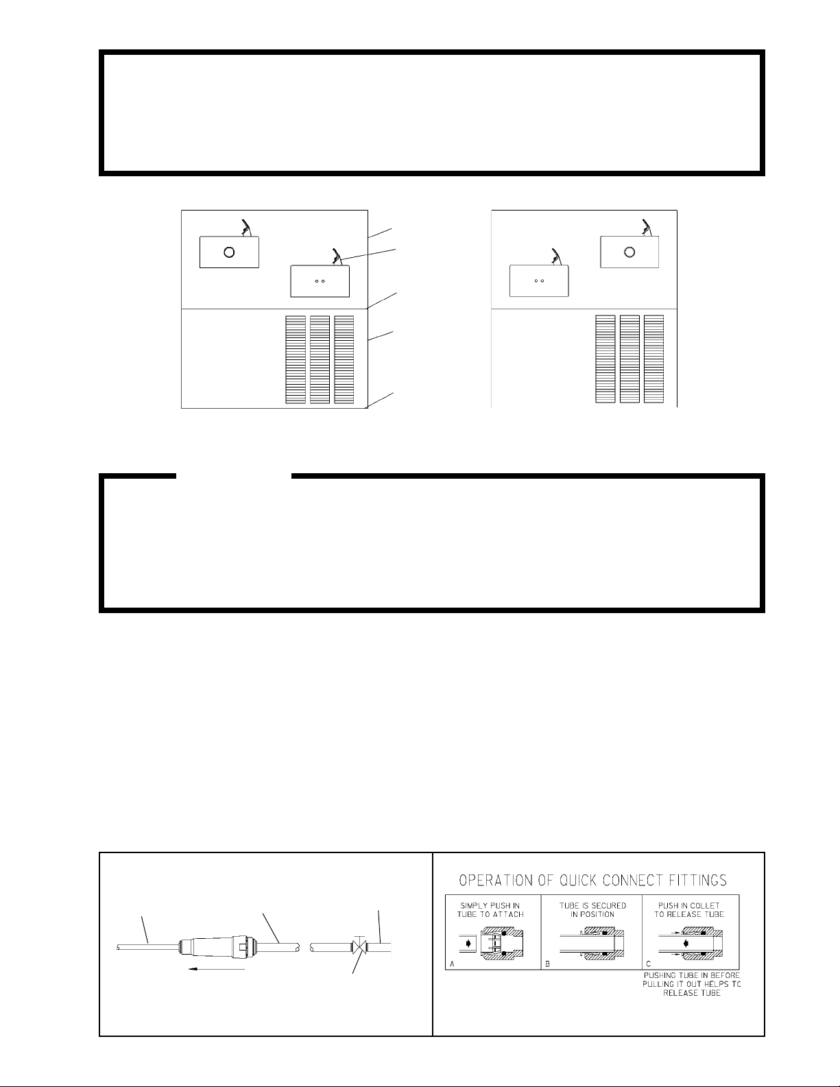
SEE FIG. 7
42
14
42
ERO28C ERO28RAC
®
Installer
To assure you install this model easily and correctly,
PLEASE READ THESE SIMPLE INSTRUCTIONS BEFORE STARTING THE
INSTALLATION. CHECK YOUR INSTALLATION FOR COMPLIANCE WITH
PLUMBING, ELECTRICAL AND OTHER APPLICABLE CODES. After installation, leave
these instructions inside the fountain for future reference.
IMPORTANT
ALL SERVICE TO BE PERFORMED BY AN AUTHORIZED SERVICE PERSON
IMPORTANT! INSTALLER PLEASE NOTE.
THE GROUNDING OF ELECTRICAL EQUIPMENT SUCH AS TELEPHONE, COMPUTERS, ETC. TO
WATER LINES IS A COMMON PROCEDURE. THIS GROUNDING MAY BE IN THE BUILDING OR MAY
OCCUR AWAY FROM THE BUILDING. THIS GROUNDING CAN CAUSE ELECTRICAL FEEDBACK
INTO A FOUNTAIN, CREATING AN ELECTROLYSIS WHICH CAUSES A METALLIC TASTE OR AN
INCREASE IN THE METAL CONTENT OF THE WATER. THIS CONDITION IS AVOIDABLE BY USING
THE PROPER MATERIALS AS INDICATED. ANY DRAIN FITTINGS PROVIDED BY THE INSTALLER
SHOULD BE MADE OF PLASTIC TO ELECTRICALLY ISOLATE THE FOUNTAIN FROM THE BUILDING
PLUMBING SYSTEM.
1/4" O.D. TUBE
WATER INLET
TO COOLER
3/8" O.D. UNPLATED
COPPER TUBE CONNECT
COLD WATER SUPPLY
NOTE: WATER FLOW
DIRECTION
BUILDING WATER
INLET
SERVICE STOP
(NOT FURNISHED)
FIG. 2FIG. 1
97114C (Rev. F - 01/01)
Page 2

ERO28C*B ER028RAC*B
FIG. 3
ERO28RAC
ERO28C
97114C (Rev. F - 01/01)
PAGE 2
LEGEND
A = 3/8" O.D. TUBE CONNECT (CHILLER WATER OUTLET)
B = 3/8" O.D. TUBE CONNECT (CHILLER WATER INLET) SHUT OFF VALVE BY OTHERS
C = 1-1/4" TRAP FURNISHED
D = ELECTRICAL INLET
Page 3

ERO28C*B ERO28RAC*B
INSTALLATION INSTRUCTIONS
1. Install mounting frame. See mounting frame instructions.
2. Install remote chiller. Remove front panel of chiller. Slide chiller onto the shelf and position it to the left within the guides on the shelf.
3. Attach solenoid valve assy to the underside of cross member of mounting frame on electric eye unit. See Figure 9.
4. Make water supply connections. Install a shut-off valve and union connection to building water supply (valve and union not provided). Turn on the
water supply and flush the line thoroughly.
5. Make connection between remote chiller and building supply line. Remove the 3/8" x 1/4" union from the chiller inlet tube and install it on the water
inlet line of the upper fountain. Install the strainer on the chiller inlet tube. Install a 3/8" O.D unplated copper water line between the valve and the
cooler. Remove all burrs from the outside of the water line. Insert the 3/8" water line into the inlet side of the strainer by pushing it in until it reaches
a positive stop, approximately 3/4" (19mm). See Figures 2 and 4. DO NOT SOLDER TUBES INSERTED INTO THE STRAINER AS DAMAGE TO THE
O-RINGS MAY RESULT.
6. Make connection between remote chiller and solenoid valve assy. Install the 3/8" tee (provided) on the chiller outlet tube. Install the 3/8" stem x 1/4"
O.D. tube union (provided) into 3/8" tee (See Fig. 4). Install 1/4" O.D. formed tube (provided) between 3/8" stem x 1/4" O.D. tube union and the
straight fitting on solenoid valve assy.
7. Hang the upper panel on the mounting frame hanger. Align holes in the panel with holes in the mounting frame. Be sure that panel is engaged with
hanger at top of frame before releasing it.
8. Install fountains. Remove bottom cover plates on underside of fountains and save the screws. Mount the fountains to the upper panel and the wall
frame with (4) 5/16" x 3/4" (19mm) long bolts and nuts (provided). Tighten securely.
9. Connect solenoid valve assy and regulator holder in fountain with sensor by installing 1/4" O.D. x 24" straight tube (provided). Connect fountain with
push button to chiller by installing 3/8" O.D. x 30' tube (provided). Insert one end into remaining outlet of the 3/8" tee and the other end into the 3/8"
x 1/4" union that was removed from the chiller inlet and attached to the water inlet line on push button fountain.
10. Remove elbow from end of p-trap and attach it to drain tube. Re-attach elbow to p-trap and cut waste tube to required length using plumbing
hardware and trap as a guide.
11. Connect power cord of sensor to solenoid valve by running it through the back panel and connecting it as shown in Fig. 5. Connectors may be
connected to either terminal on solenoid valve. Attach ground wire to solenoid valve bracket with green ground screw.
12. Turn on water supply. Release air from tank by interrupting infrared beam; steady stream of water assures all air is removed. The sensor has a 30
second maximum ON time. It may be necessary to step away from beam a few times to allow chiller tank to refill. Check for leaks.
13. These products are designed to operate on 20-105 PSIG supply line pressure. If inlet pressure is above 105 PSIG, a pressure regulator must be
installed in the supply line. Any damage caused by reason of connecting these products to supply line pressures lower than 20 PSIG or higher than
105 PSIG is not covered by warranty.
14. Make electrical connections to chiller. See chiller instructions.
15. Check stream height from bubbler. Stream height is factory set at 35 PSI . If supply pressure varies greatly from this, remove items 29 and 37
and adjust the screw on the regulator (item 8). Clockwise adjustment will raise stream height and counter-clockwise will lower stream height. For best
adjustment stream height should hit basin approximately 6-1/2" (165mm) from the bubbler.
16. Mount lower panel. Loosen the (2) #10-24 x 5/8" (16mm) screws at frame bottom lip. Slide upper tongue of lower panel under lower edge of already
installed upper panel. Tighten previously loosened screws securely.
17. Replace bottom cover plate to fountain basin using screws provided. Tighten securely.
FIG. 4
40
39
19
16
PAGE 3
33
17
8
29
36
FIG. 5
20
25
41
7
24
28
38
21
37
30
27
26
34
23
97114C (Rev. F - 01/01)
Page 4

1
2
3
4
5
6
7
8
9
10
11
12
13
14
15
16
17
18
19
20
21
22
23
24
25
26
27
28
29
30
31
32
33
34
35
36
37
38
39
40
41
42
43
44
45
PART NO.ITEM NO.
A54874
50934C
50168C
70012C
LK464
15005C
50986C
61313C
55000604
27623C
55000661
55000665
26839C
26833C
110711942550
55996C
40045C
70055C
70745C
22525C
22526C
27057C
27240C
31272C
31376C
31384C
34783003
38417001
56082C
70016C
45662C
45663C
50203C
51409C
70022C
70208C
70256C
70817C
70852C
75491C
75507C
111008343890
111577243890
111577343890
56092C
ERO28C*B ER028RAC*B
PARTS LIST
DESCRIPTION
Orifice Assy
Housing Assy
Pedestal
Bubbler Locknut
Drain
Retaining Nut
Regulator Holder
Regulator
Fountain Body-Short
Fountain Body-Long
Bottom Cover Plate-Short
Bottom Cover Plate-Long
Upper Panel
Lower Panel
Screw #8-32 X .38" TH
Strainer
Hex Nut
Speed Nut
Union-3/8 X 1/4
Regulator Mounting Bracket-Long Ftn
Solenoid Mounting Bracket
Regulator Mounting Bracket-Short Ftn
Sensor Support Mounting Bracket
Solenoid Valve Assy
Power Cord
Sensor Assy
Washer - Star #10
Screw - #8-18 X .37 HHSM
Nut - Regulator
Hex Nut #10-32
Push Button
Push Button Sleeve
Strain Relief
Spacer - 1/2 X .44
Set Screw #6-32 X .31"
Screw - #10-24 X .38 PHTC
Screw - 1/4-20 X .38 HHTC
Elbow - 1/4 X 1/4
Tee - 3/8
Union - 3/8 Stem X 1/4 Tube
Fitting - 1/4 NPTF X 1/4 O.D.
Screw - #10-24 X .62 HHMS
Screw- 5/16-18 X .75
Hex Nut - 5/16-18
Poly Tubing 48" (Cut To Length)
TROUBLE SHOOTING AND MAINTENANCE
1. Orifice Assy: Minerals deposits on orifice can cause water flow to spurt or not
regulate. Mineral deposits may be removed from the orifice with a small round
file not over 1/8" diameter or a small diameter wire. CAUTION: Do not file or
cut orifice materials.
2. Stream Regulator: If orifice is free of material deposits regulate water flow
according to instructions on page 3.
3. Sensor Control: The sensor has a 2 second delay time. If sensor fails to
operate valve mechanism or operates erratically, check the following:
a) Ensure there are no obstructions within a 40 inch radius from the front of
fountain.
b) Check wire connections at the solenoid valve and at the sensor.
CAUTION: Make sure unit is unplugged before checking any wiring.
c) Ensure proper operation of solenoid valve. If there is an audible clicking
sound yet no water flows, look for an obstruction in the valve itself or
elsewhere in the water supply line. WARNING: Do not expose sensor to
direct sunlight.
4. Sensor Range Adjustment: The electronic sensor used in this fountain is
factory pre-set for a "visual" range of 36 inches. If actual range varies greatly
from this, or a different setting is desired, follow the range adjustment
procedure below:
a) Remove bottom cover of fountain.
b) Remove sensor by removing washers and nuts that secure sensor on studs.
c) Locate range adjustment screw between the red lenses of the sensor, then
with a small tip screwdriver, rotate the range adjusting screw clockwise to
increase range or counter-clockwise to decrease range. 1/4 turn of screw is
equal to approximately 12 - 18 inches of range.
CAUTION: Complete range of sensor (24 - 48 inches) is only one turn of the
adjusting screw.
d) Remount sensor on studs and replace bottom cover.
45
SEE FIG. 8
9
43, 44
45
10
43, 44
1
32
31
17
35
22
ELKAY MANUFACTURING COMPANY 2222 CAMDEN COURT OAK BROOK, IL 60523 630.574.8484
97114C (Rev. F - 01/01)
SEE FIG. 5
12, 15, 18
FIG. 6
2
NOTE: WHEN INSTALLING
REPLACEMENT BUBBLER
AND PEDESTAL, TIGHTEN
NUT (ITEM 4) ONLY TO HOLD
PARTS SNUG IN POSITION. DO
3
NOT OVER TIGHTEN.
4
6
FIG. 7
7
8
24
28
ERO28C ERO28RAC
FIG. 8
FOR PARTS, CONTACT YOUR LOCAL DISTRIBUTOR OR CALL 1.800.323.0620
FIG. 9
PAGE 4
5
11, 15, 18
 Loading...