

Page 1
EDFPB117FP EDFPB117RFP EDFPBVM1 17FP EDFPBVM1 17RFP
Installation/Care/Use Manual
®
Swirlflo
Freeze Resistant Fount ain
Installer
T o assure you install this model easily and correctly , PLEASE READ THESE SIMPLE INSTRUCTIONS BEFORE ST ARTING THE INST ALLA TION. CHECK YOUR INST ALLATION
FOR COMPLIANCE WITH PLUMBING , ELECTRICAL AND OTHER APPLICABLE CODES.
After installation, leave these instructions with the building owner for future reference.
This Freeze Resistant Fountain is shipped in three separate cartons. The second & third
carton contains the Freeze Resistant Package LKFRB1 that is installed on an interior heated
wall. Refer to the Freeze Resistant Package for the rough-in dimensions for installation.
IMPORTANT
ALL SERVICE TO BE PERFORMED BY AN AUTHORIZED SER VICE PERSON
IMPORTANT! INSTALLER PLEASE NOTE.
THE GROUNDING OF ELECTRICAL EQUIPMENT SUCH AS TELEPHONE, COMPUTERS, ETC. T O WA TER
LINES IS A COMMON PROCEDURE. THIS GROUNDING MA Y BE IN THE BUILDING OR MA Y OCCUR A WA Y
FROM THE BUILDING . THIS GROUNDING CAN CAUSE ELECTRICAL FEEDBACK INTO A FOUNT AIN, CREA T ING AN ELECTROL YSIS WHICH CAUSES A MET ALLIC T ASTE OR AN INCREASE IN THE MET AL CONTENT
OF THE WA TER. THIS CONDITION IS A VOIDABLE BY USING THE PROPER MA TERIALS AS INDICA TED.
ANY DRAIN FITTINGS PROVIDED BY THE INST ALLER SHOULD BE MADE OF PLASTIC TO ELECTRICALL Y
ISOLA TE THE FOUNT AIN FROM THE BUILDING PLUMBING SYSTEM.
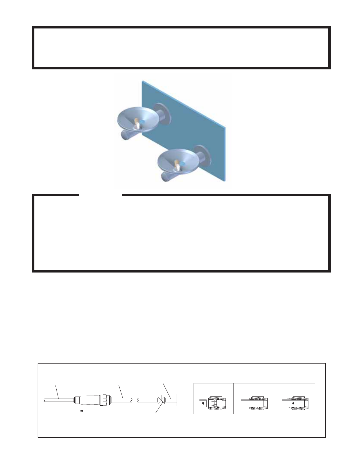
1/4" O.D. TUBE
WATER INLET
TO COOLER
FIG. 1
3/8" O.D. UNPLATED
COPPER TUBE CONNECT
COLD WATER SUPPLY
NOTE: WATER FLOW
DIRECTION
BUILDING WATER
INLET
SERVICE STOP
(NOT FURNISHED)
OPERA TION OF QUICK CONNECT FITTINGS
SIMPLY PUSH IN
TUBE TO ATTACH
TUBE IS
SECURED
IN POSITION
PUSH IN COLLET
TO RELEASE TUBE
PUSHING TUBE IN BEFORE
PULLING IT OUT HELPS TO
FIG. 2
98010C (Rev. C - 6/08)
1
RELEASE TUBE
Page 2
BACK
PANEL
SURFACE
MOUNTING
PLATE
37"
940mm
36 1/2"
927mm
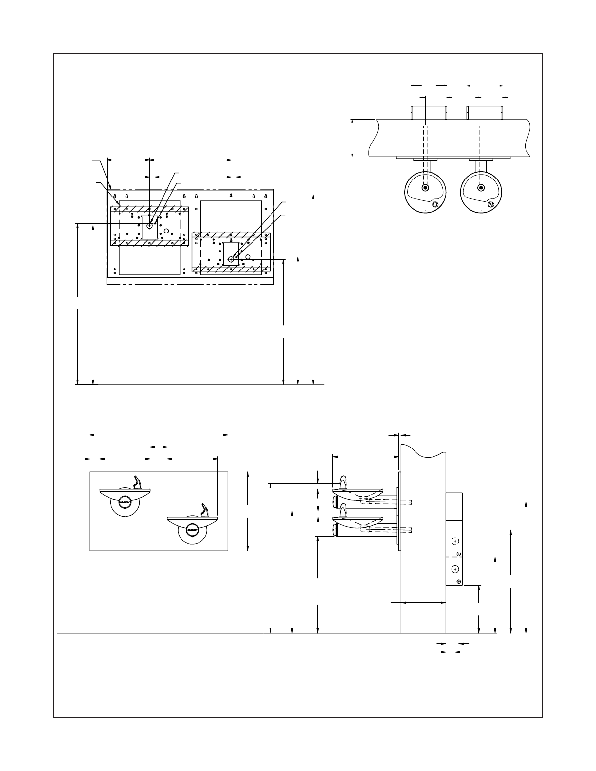
EDFPB117FP EDFPB117RFP EDFPBVM117FP EDFPBVM1 17RFP
EDFPB(V)M1 17FPC ROUGH-IN
12"
305mm
MAX. WALL
THICKNESS
9 3/4"
248mm
1 1/4"
32mm
18 3/4"
476mm
B
A
1 1/4"
32mm
28 3/4"
730mm
B
A
29 1/4"
743mm
43 5/8"
1108mm
12 1/8"
307mm
7 1/4"
184mm
12 1/8"
307mm
7 1/4"
184mm
FINISHED FLOO R
38 1/2"
978mm
4 3/4"
2 7/8"
73mm
14"
356mm
121mm
14"
356mm
FINISHED FLO O R
21 15/16"
557mm
41 11/16"
1060mm
1 5/8"
41mm
1 5/8"
41mm
33 15/1 6"
863mm
ADA
REQUIREMENT
27"
686mm
18 3/8"
467mm
12"
305mm
MAX. WALL
THICKNESS
FIG. 3
LEGEND:
A = 7/8" (22mm) DIA. HOLE FOR W ATER SUPPLY TUBE
B = 1-3/4" (44mm) DIA. HOLE FOR WASTE LINE
*Note: All dimensions are taken from the finished floor on the side of the wall
that the fountain is installed on.
5/8"
16mm
21 1/8"
537mm
13 5/16"
339mm
3 5/8"
2 5/8"
66mm
91mm
NOTE: REINFORCE WALL IN SHADED
AREAS.
28 3/4"
729mm
36 1/2"
926mm
98010C (Rev. C - 6/08)
2
Page 3
43 1/2"
1105mm
MPW200
MTG. PLT.
37"
940mm
C
36 1/2"
927mm
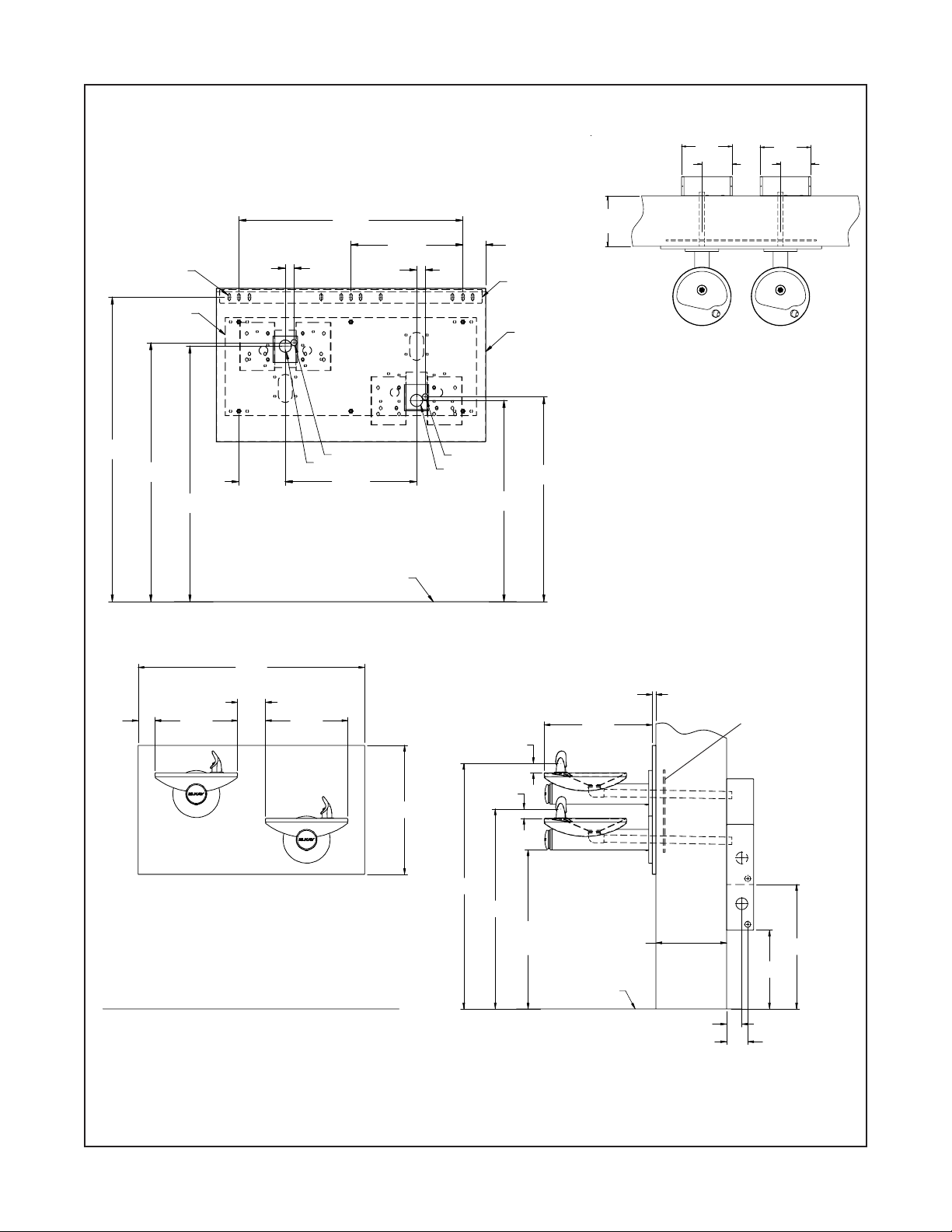
EDFPB117FP EDFPB117RFP EDFPBVM1 17FP EDFPBVM1 17RFP
EDFPB1 17FPC ROUGH-IN
12 1/8"
307mm
12"
305mm
MAX. WALL
THICKNESS
6 5/8"
168mm
1 1/4"
32mm
B
32"
813mm
A
18 3/4"
476mm
1 1/4"
32mm
16"
406mm
3 1/4"
82mm
HANGER BRACK ET
BACK PANEL
A
B
28 3/4"
730mm
29 1/4"
743mm
7 1/4"
184mm
12 1/8"
307mm
7 1/4"
184mm
FINISHED FLOOR
38 1/2"
978mm
4 3/4"
2 7/8"
73mm
LEGEND:
14"
356mm
121mm
14"
356mm
21 15/16"
557mm
41 11/16"
1059mm
FIG. 4
1 5/8"
41mm
33 15/16"
862mm
1 5/8"
41mm
27"
686mm
ADA
REQUIREMENT
A = 7/8" (22mm) DIA. HOLE FOR W ATER SUPPLY TUBE
B = 1-3/4" (44mm) DIA. HOLE FOR WASTE LINE
C = 3/8" (10mm) DIA. SLOTS FOR MOUNTING HANGER BRACKET TO WALL
18 3/8"
467mm
FINISHED FLOOR
5/8"
16mm
12"
305mm
MAX. WALL
THICKNESS
2 5/8"
66mm
MPW200 MTG . PL T .
REF . SEPARA TE
INSTALLATION
INSTRUCTIONS
FOR DETAILS
21 1/8"
537mm
13 3/8"
339mm
3 5/8"
91mm
*Note: All dimensions are taken from the finished floor on the side of the wall
that the fountain is installed on.
3
98010C (Rev. C - 6/08)
Page 4

EDFPB117FP EDFPB117RFP EDFPBVM117FP EDFPBVM1 17RFP
EDFPB1 17RFPC ROUGH-IN
12 1/8"
307mm
7 1/4"
184mm
12"
305mm
MAX. WALL
32"
813mm
16"
1 1/4"
C
32mm
1 1/4"
32mm
406mm
3 1/4"
82mm
HANGER BRACK ET
THICKNESS
12 1/8"
307mm
7 1/4"
184mm
43 1/2"
1105mm
2 7/8"
73mm
MPW200
MTG. PLT.
29 1/4"
743mm
28 3/4"
730mm
14"
356mm
6 5/8"
168mm
38 1/2"
978mm
4 3/4"
121mm
B
14"
356mm
A
18 3/4"
476mm
FINISHED FLOOR
21 15/16"
557mm
1 5/8"
41mm
A
B
BACK PANEL
37"
940mm
36 1/2"
927mm
1 5/8"
41mm
18 3/8"
467mm
5/8"
16mm
MPW200 MTG . PL T .
REF . SEPARA TE
INSTALLATION
INSTRUCTIONS
FOR DETAILS
41 11/16"
1059mm
33 15/16"
862mm
27"
686mm
ADA
REQUIREMENT
LEGEND:
FIG. 5
A = 7/8" (22mm) DIA. HOLE FOR W ATER SUPPLY TUBE
B = 1-3/4" (44mm) DIA. HOLE FOR WASTE LINE
C = 3/8" (10mm) DIA. SLOTS FOR MOUNTING HANGER BRACKET TO W ALL
*Note: All dimensions are taken from the finished floor on the side of the wall
that the fountain is installed on.
98010C (Rev. C - 6/08)
4
12"
305mm
MAX. WALL
THICKNESS
FINISHED FLOOR
2 5/8"
66mm
13 3/8"
339mm
3 5/8"
91mm
21 1/8"
536mm
Page 5

EDFPB117FP EDFPB117RFP EDFPBVM1 17FP EDFPBVM1 17RFP
INSTALLATION INSTRUCTIONS
1. Wall should already be framed for the fountain using the positioning dimensions shown in Fig's. 3, 4, or 5. Shown
dimensions pertain to installation location (framing must support up to 300 lbs. weight). These dimensions are required for compliance
with ANSI S tandard A117.1/ADA requirements.
2. The freeze resistant package must be mounted on an interior wall in a heated area. The room temperature of the interior heated area
must be 50° F (10° C) or higher. The freeze resistant package may be surface or recessed mounted. If recess mounted the surface of
the cover must be flush with the interior wall surface. The package is furnished with screws for mounting the cover to the box. If the
box is recess mounted, do not fasten the top and bottom of the cover to the box. Use the holes on the front only.
3. T o assemble the operating cable to the sleeve inside the fountain arm you will need to remove cap screw (Item 18, See Fig. 6) and then
remove Push Button and Pin (Items 12 & 13, See Fig. 6). Remove screw (Item 20, See Fig. 6) and you will now be able to remove the
Sleeve (Item 7, See Fig. 6) to get access to the adjustment nuts for additional adjustability . (Fountain should be mounted to exterior wall)
Create a loop in the cable and thread the free end of the cable through the wall into the freeze resistant box. The adjustment nuts should
be in the middle of threaded area on the operating cable. See Fig. 6.
4. Connect free end of operating cable to the valve-operating bracket. The end of the cables must be recessed into the indents on the
pivot brackets.
5. Remove cable free play by adjusting the jam nuts on the ends of the operating cable. See Fig. 6.
6. Connect water line from fountain bubbler into freeze resistant box. The connection to the box uses a quick connect water fitting.
Position the water line, in the fountain, to drain back into interior mounted box. Any water left st anding, in the exterior line, can freeze. T o
insure positive draining of the bubbler supply tube, excess length should be trimmed off and discarded.
7. Connect drain and water supply lines to the freeze resistant fountain. Inline strainer must be used on the inlet water line.
ST ART UP
1. Turn on building water supply and check all connections for leaks. Repair as required.
2. Stream height is factory set at 35 PSI. If stream height needs to be changed adjust the regulator in the freeze resistant package.
Clockwise adjustment raises stream height, counter clockwise adjustment will lower stream.
3. Adjust operating cable as required. Cable system should have a minimal amount of free play to allow for proper valve operation. If the
system is too tight the valve will stay in the on position creating constant water flow . Too much free play will result in non-operation of
the valve with the push-buttons.
4. Note: Water from the drain back tube in the freeze resistant package will continue to run while the valve is actuated.
5. After cable system is adjusted properly , stuf f flexible insulation into any openings between the outside wall and the interior box.
6. Recheck all connections. If all connections are leak free replace cover(s) on the freeze resistant box(es) and fountain(s).
CABLE SHEA TH ADJUSTMENT
20
7
T o Increase Free Play
T o Reduce Free Play
12, 13
18
FIG . 6
98010C (Rev. C - 6/08)
5
Page 6

EDFPB117FP EDFPB117RFP EDFPBVM117FP EDFPBVM1 17RFP
3
4
1
2
NOTE:
When installing replacement bubbler and
pedestal, tighten nut (Item 5) only to hold
parts snug in position. Do Not Overtighten.
BASIN
5
Bubbler Details
24
98010C (Rev. C - 6/08)
25
BASIN
26
VANDAL RESIST ANT
BUBBLER DETAIL
FIG. 7 - Bubbler Details
6
Page 7

ITEM NO.
1
2
3
4
5
6
7
8
9
10
11
12
13
14
15
16
17
18
19
20
21
22
23
24
25
26
27
NS
P ARTS LIST
PAR T NO.
56073C
40322C
56011C
55997C
75580C
15027C
15025C
28474C
28473C
45767C
28343C
45848C
45821C
56163C
45769C
45768C
56092C
75669C
70817C
111008343890
28392C
28393C
70432C
75560C
98118C
100322740560
15009C
28844C
28845C
27090C
EDFPB117FP EDFPB117RFP EDFPBVM1 17FP EDFPBVM1 17RFP
DESCRIPTION
Bubbler Assy
Orifice Assy
Housing Assembly
Pedestal
Bubbler Locknut
Brkt - Swirlflow
Assy - Sleeve/Button Swirlflo
Basin - Swirlflow
Lower Shell
Fountain Body
Cover Plate
Button - Push Swirlflo
Pin - Push Button Swirlflo FP
Gasket - Drain
Assy - Drain/Tailpipe
Drain - Plug 1-1/2"
Poly Tubing (Cut To Length)
Cap Screw - #6-32 x 1.25"
Fttng - Elbow 1/4 x 1/4
Screw - #10-24 x .62 HHSM
Panel - Back RH ADA
Panel - Back LH ADA
Screw - #8-32 x .38 THMS
Screw - 5/16-18 x1.00 HHMS
Bubbler Assembly VR
Gasket - Black .68 x 1.03 VR
Nipple - Bubbler VR
Back Panel Assy. RH ADA
Back Panel Assy. LH ADA
Hanger Bracket
FIG. 8
Installing Back Panel: When installing back panel assy.
(Item 27) with MPW (Mounting Plate), attach channel braces
as shown above. Remove the protective backing from the
tape installed on the braces. Line up the corresponding holes
in the braces and back panel and press firmly in place.
27
16
12
SEE FIG. 7
9
6
7
20
20
8
14
5
23
1 1,22
17,19
15
10
13
FOR PARTS, CONT ACT YOUR LOCAL DISTRIBUTOR OR CALL 1.800.323.0620
ELKAY MANUF ACTURING COMP AN Y • 2222 CAMDEN COURT • OAK BROOK, IL 60523 • 630.574.8484
18
FIG. 9
7
98010C (Rev. C - 6/08)
 Loading...