

Elkay ECP8*1H Series, ECP8*3H Series, ECP8*2H Series Installation, Care & Use Manual
ECP8*1H ECP8*2H ECP8*3H
Refrigeration Package
INSTALLATION, CARE & USE MANUAL
Note: Danger! Electric shock hazard. Disconnect power before servicing unit.
USES HFC-134A REFRIGERANT
INSTALLATION
1. Insure proper ventilation. In fully recessed drinking fountains be sure condenser faces louver panel and is
within 1/2” (13 mm) of louver panel when panel is in place.
2. Water inlet is 3/8” (10 mm) O.D. unplated tube . Contractor to supply connections as required.
3. Connecting lines to be made of unplated copper. Thoroughly ush all lines to remove all foreign matter
before connecting to cooler.
4. Connect cooler to building supply with a shut-off valve and install a 3/8” (10 mm) unplated water line
between the valve and cooler. Remove burrs from outside of water line. Insert water line into bulkhead union
until it reaches a positive stop, approximately 3/4” (19 mm).
NOTE: DO NOT SOLDER TUBES INSERTED INTO THE STRAINER AS DAMAGE TO THE O-RINGS MAY
RESULT.
5. Electrical: Make sure power supply is identical in voltage, cycle, and phase to that specied on cooler serial
plate. Never wire the compressor directly to the power supply.
IMPORTANT! INSTALLER PLEASE NOTE:
The grounding of electrical equipment such as telephone, computers, etc., to water lines is a common procedure. This
grounding may be in the building, or may occur away from the building. This grounding can cause electrical feedback
into a water chiller, creating an electrolysis which causes a metallic taste or an increase in the metal content of the
water. This condition is avoidable by using the proper materials indicated below. Drain ttings which are provided by
the installer should be plastic to electrically isolate the chiller from the building plumbing system.
START-UP
1. Open supply line valve.
2. Purge all air from all water lines by operating bubbler valve of fountain to which cooler is connected.
A steady stream ow assures that all air is removed.
3. Rotate fan blade to assure proper clearance and free action.
4. Connect to proper electrical power.
TROUBLE SHOOTING & MAINTENANCE
Temperature Control: Factory-set for 50°F water (± 5°) under normal conditions. For colder water, adjust screw
on item no. 5.
Ventilation: Cabinet louvers and condenser ns should be periodically cleaned with a brush, air hose, or vacuum
cleaner. Excess dirt or poor ventilation can cause no cold water and compressor cycling on the overload
protector.
Lubrication: Motors are lifetime lubricated.
Actuation of Quick Connect Water Fittings: Cooler is provided with lead-free connectors which utilize an o-ring
seal. To remove tubing from the ttings, relieve water pressure, push in on gray collar while pulling on the
tubing. To insert tubing, push tube straight into tting until it reaches a positive stop, approximately 3/4”.
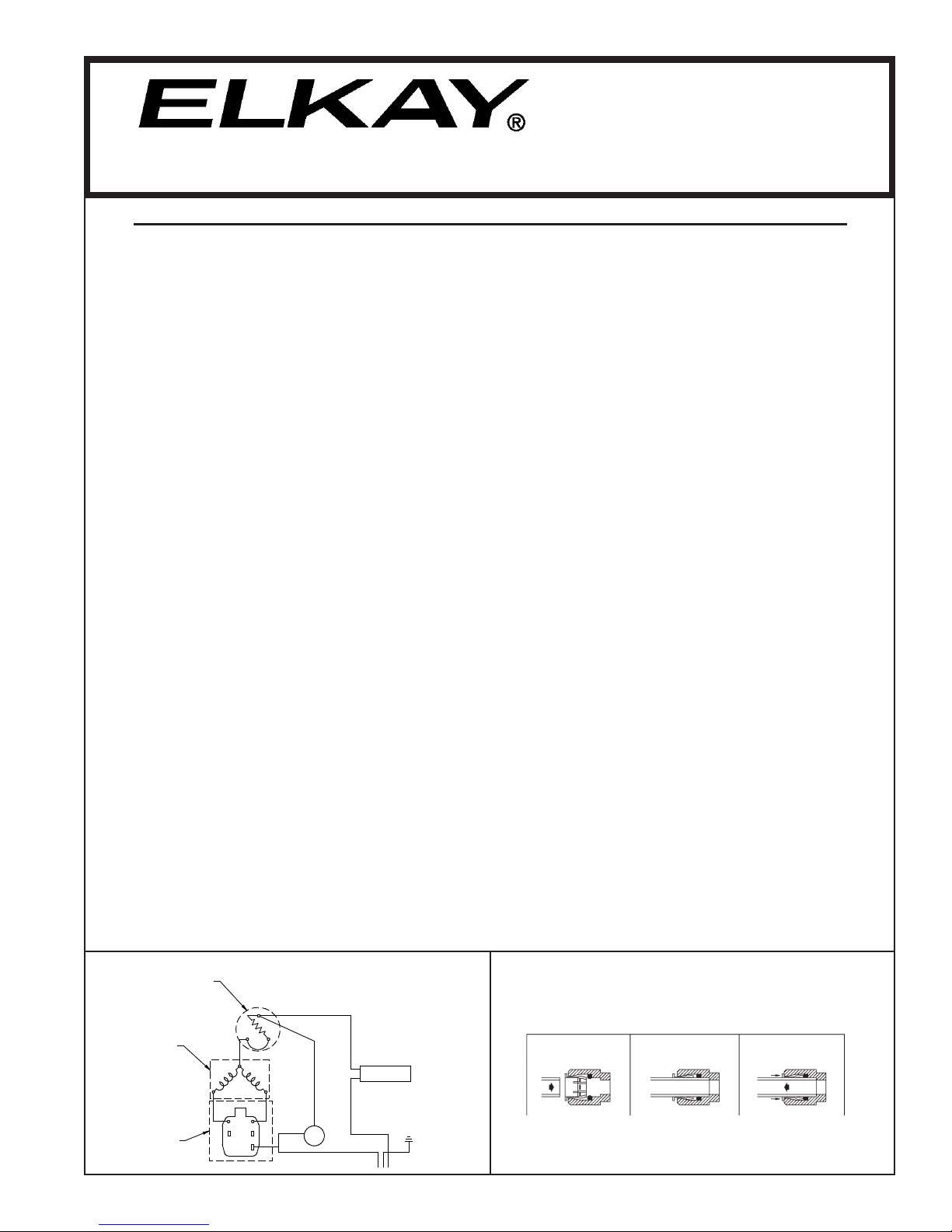
OVERLOAD
WIRING DIAGRAM
OPERATION OF QUICK CONNECT FITTINGS
3
1
COM
PRESSOR
S M
RELAY
2
C
56
23
1
FAN
COLD CONTROL
(WATER)
BLACK
WHITE GROUND
Page 1
SIMPLY PUSH IN
TUBE TO ATTACH
TUBE IS SECURED
IN POSITION
PUSH IN COLLET
TO RELEASE TUBE
PUSHING TUBE IN BEFORE
PULLING IT OUT HELPS TO
RELEASE TUBE
1000003083 (Rev. B - 05/16)
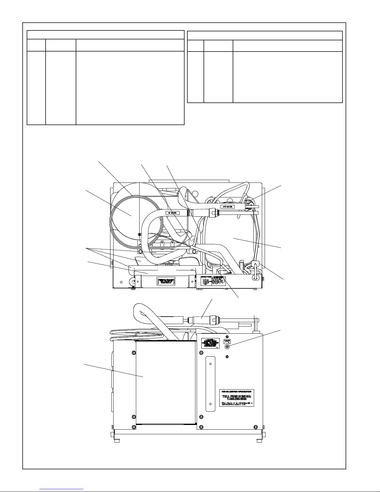
ECP8*1H ECP8*2H ECP8*3H
ITEM
NO.
1
2
3
4
5
*6
7
8
9
10
11
12
PART
NO.
98724C
98775C
98778C
55996C
98773C
36322C
0000000238
36208C
98777C
98776C
66703C
20282C
115V PARTS LIST
DESCRIPTION
kIT - EVAPORATOR REPLACE ASSY
KIT - FAN MOTOR/BLADE//NUT/SHROUD
KIT - HEATX/DRIER
STRAINER
KIT - COLD CONTROL/SCREWS
COMPRESSOR SERV. PAK
KIT - ELECT/RELAY/COVER/OVERLOAD
POWERCORD
KIT - COMPR MTG/GROMMETS/CLIPS/STUDS
KIT - CONDENSER/DRIER
DRIER
BRACKET - FAN MTG
3
12
11
1
220V 50/60HZ PARTS LIST
ITEM
PART
NO.
13
NO.
2
0000000244
0000000245
*6
1000002147
1000002146
7
98751C
98752C
8
31506C
56237C
*INCLUDES RELAY & OVERLOAD. IF UNDER WARRANTY
REPLACE WITH SAME COMPRESSOR USED IN ORIGINAL
ASSEMBLY.
NOTE: ALL CORRESPONDENCE PERTAINING TO ANY OF THE
ABOVE WATER COOLERS OR ORDERS FOR REPAIR PARTS
MUST INCLUDE MODEL NO. AND SERIAL NO. OF COOLER,
NAME AND PART NO. OF REPLACEMENT PART.
KIT - FAN MTR/BLADE/NUT/SHROUD (50 HZ)
KIT - FAN MTR/BLADE/NUT/W/O SHRD(60 HZ)
COMP SERV. PAK (50 HZ)
COMP. SERV. PAK (60 HZ)
KIT - ELEC/RELAY/CVR/OL (50 HZ)
KIT - ELEC/RELAY/CVR/OL (60 HZ)
POWER CORD (50/60 HZ)
SHROUD-FAN
DESCRIPTION
9
10
13
2
6
8
4
7
5
REPAIR SERVICE INFORMATION TOLL FREE NUMBER 1.800.260.6640
FOR PARTS, CONTACT YOUR LOCAL DISTRIBUTOR OR CALL 1.800.834.4816
ELKAY MANUFACTURING COMPANY • 2222 CAMDEN COURT • OAK BROOK, IL 60523 • 630.574.8484
1000003083 (Rev. B - 05/16)
PAGE 2
 Loading...