

Page 1

Operating manual
Swing gate openers
ZENIT-S 300/302 – ZENIT-S 450/452
- Long articulated arm -
Inhaltverzeichnis
Translation of original operating manual
D-ID: V1_17 – 09.14
ELKA-Torantriebe GmbH u. Co. Betriebs KG
Dithmarscher Str. 9
25832 Tönning
Germany
Phone: +49-(0) 48 61 - 96 90-0
Fax: +49-(0) 48 61 - 96 90-90
E-mail: info@ELKA-Torantriebe.de
Internet: www.ELKA-Torantriebe.de
Page 2

Inhaltverzeichnis
2
1
Preface ............................................................................................................................................ 4
1.1 Information regarding the operating manual ........................................................................... 5
1.2 Symbol explanation ................................................................................................................. 5
1.3 Copyright ................................................................................................................................. 5
2 Safety ............................................................................................................................................... 6
2.1 General notes of safety ........................................................................................................... 6
2.2 Notes on safety for the operation ............................................................................................ 6
2.3 Notes on safety for the operation with radio remote control .................................................... 6
2.4 Intended usage ........................................................................................................................ 6
2.5 Danger, which could emanate from the site of operation ........................................................ 7
3 Transportation and storing ............................................................................................................... 7
3.1 Transportation inspection ........................................................................................................ 7
3.2 Storing ..................................................................................................................................... 7
4 Declaration of incorporation ............................................................................................................. 8
4.1 Declaration of conformity ......................................................................................................... 9
4.2 Nameplate ............................................................................................................................... 9
5 Technical data ............................................................................................................................... 10
6 Configuration ................................................................................................................................. 11
7 Function description ...................................................................................................................... 12
8 Mechanical installation .................................................................................................................. 13
8.1 Notes of safety ....................................................................................................................... 13
8.2 Required tools ........................................................................................................................ 13
8.3 Protective equipment ............................................................................................................. 13
8.4 Scobe of delivery ................................................................................................................... 14
8.5 Dimensions ............................................................................................................................ 14
8.6 Installation dimensions .......................................................................................................... 15
8.7 Max. opening angle ............................................................................................................... 16
8.8 Installation at the gatepost ..................................................................................................... 16
8.9 Adjusting the internal stops ................................................................................................... 22
9 Electrical installation ...................................................................................................................... 24
9.1 Notes of safety ....................................................................................................................... 24
9.2 Installation example ............................................................................................................... 24
9.3 Cable connections ................................................................................................................. 25
9.4 Programming the gate opener ............................................................................................... 26
10 Controller MO 36 ....................................................................................................................... 27
10.1 Input terminals of the controller ............................................................................................. 27
10.1.1 Photoelectric barrier connection .................................................................................... 28
10.1.2 Safety contact profile ..................................................................................................... 29
10.2 Output terminals of the controller .......................................................................................... 31
10.3 Buttons on the controller ........................................................................................................ 32
10.4 LEDs on the controller ........................................................................................................... 32
10.5 Clip-on module....................................................................................................................... 33
Page 3

Inhaltverzeichnis
3
10.5.1
Clip-on timer module ASU2 (optional) ........................................................................... 33
10.5.2 Traffic light module AMO34A (optional) ........................................................................ 34
10.6 Programmin controller MO 36 ............................................................................................... 35
10.6.1 Sequence p1: Learning the running distance ............................................................. 37
10.6.2 Sequence p2: Adjusting of force and speed ............................................................... 38
10.6.3 Sequence p3: Time lag of the pedestrian wing during closing ................................... 39
10.6.4 Sequence p4: Time lag of the main wing during opening ........................................... 39
10.6.5 Sequence p5: Learning and deleting of radio remote control codes .......................... 40
10.6.6 Sequence p6: Automatic closure for complete opening .............................................. 41
10.6.7 Sequence p7: Automatic closure for pedestrian wing ................................................. 42
10.6.8 Sequence p8: Pre-warning .......................................................................................... 43
10.6.9 Sequence p9: Photoelectric barrier function ............................................................... 44
10.6.10 Sequence pa: Photoelectric barrier testing ............................................................. 45
10.6.11 Sequence pb: Lockage function of the photoelectric barriers ................................. 46
10.6.12 Sequence pc: Pressure relief for electromagnetic bolt ........................................... 47
10.6.13 Sequence pd: Wind blast suppression .................................................................... 47
10.6.14 Sequence pe: Multi-function relay ........................................................................... 48
10.6.15 Sequence pf: Return to origgnal setting ................................................................. 48
10.6.16 Sequence pp: Storing of data .................................................................................. 48
11 Normal operation ....................................................................................................................... 49
11.1 Operation with push button .................................................................................................... 49
11.2 Operation with push button and automatic closure for both wings ........................................ 49
11.3 Operation with push button and automatic closure fort he pedestrian wing ......................... 50
11.4 Emergency release during power failure ............................................................................... 50
11.4.1 Disengaging the gate opener ........................................................................................ 50
11.4.2 Engaging the gate opener ............................................................................................. 51
11.5 Power failure .......................................................................................................................... 51
11.6 Emergency mode .................................................................................................................. 52
12 Fault diagnosis .......................................................................................................................... 53
13 Care and maintenance .............................................................................................................. 54
13.1 Care instructions .................................................................................................................... 54
13.2 Service instructions ............................................................................................................... 55
13.3 Demounting the gate opener ................................................................................................. 55
14 Technical data controller MO 36................................................................................................ 56
14.1 Constant values ..................................................................................................................... 56
14.2 Changeable values and factory setting ................................................................................. 56
15 Drawings .................................................................................................................................... 57
15.1 Drawing – Swing gate opener incl. operator unit ................................................................... 57
15.2 Drawing – Operator unit ........................................................................................................ 59
16 Index .......................................................................................................................................... 61
Page 4

Preface
4
1 Preface
These operating instructions must be available on site at all times. It should be read thoroughly by all
persons who use, or service the appliances. Improper usage or servicing or ignoring the operating
instructions can be a source of danger for persons, or result in material damage. If the meaning of any
part of these instructions isn’t clear, then please contact ELKA-Torantriebe GmbH u. Co. Betriebs KG
before you use the appliance.
This applies to all setup procedures, fault finding, disposal of material, care and servicing of the
appliance.
The accident prevention regulations and applicable technical regulations (e.g. safety or electrical) and
environment protection regulations of the country in which the appliance is used also apply.
All repairs on the appliances must be carried out by qualified persons. ELKA-Torantriebe GmbH u. Co.
Betriebs KG accepts no liability for damage which is caused by using the appliance for purposes other
than those for which it is built.
ELKA-Torantriebe GmbH u. Co. Betriebs KG cannot recognise every possible source of danger in
advance. If the appliance is used other than in the recommended manner, the user must ascertain that
no danger for himself or others will result from this use. He should also ascertain that the planned use
will have no detrimental effect on the appliance itself. The appliance should only be used when all
safety equipment is available and in working order. All faults which could be a source of danger to the
user or to third persons must be eliminated immediately. All warning and safety notices on the
appliances must be kept legible.
All electrical periphery equipment which is connected to the appliance must have a CE Mark, which
ensures that it conforms to the relevant EEC regulations. Neither mechanical nor electrical alterations
to the appliance, without explicit agreement of the manufacturer, are allowed. All alterations or
extensions to the appliance must be carried out with parts which ELKA-Torantriebe GmbH u. Co.
Betriebs KG have defined as suitable for such alterations, and be carried out by qualified personnel.
Please note that with any alteration of the product, no matter whether mechanical or electrical, the
warranty expires and the conformity is revoked. Only the use of ELKA accessories and original ELKA
spare parts is allowed. In case of any contravention ELKA disclaims liability of any kind.
REMARK!
The operation of the system within CEN countries must also be conformant with the
European safety-relevant directives and standards.
We reserve the right to make technical improvements without prior notice.
Page 5
Preface
5
1.1 Information regarding the operating manual
This operating manual serves the purpose to enable the user to install, start-up, and operate the gate
opener appropriately.
The operating manual, especially the chapter safety, must be read and understood completely before
beginning any work with the gate opener. The instructions of the operating manual, especially the
notes on safety, as well as the accident prevention regulations adequate for the type of application
must absolutely be kept.
The operating manual describes gate openers with one wing but also applies to systems with 2 wings.
Variations will be pointed out explicitly.
1.2 Symbol explanation
Remarks regarding the safety of persons and the gate opener itself are marked by special symbols.
These remarks have to be absolutely observed in order to avoid accidents and material damage.
DANGER!
…points to an imminent dangerous situation, which can cause death or serious injuries if it
is not avoided.
WARNING!
…points to a potentially dangerous situation, which can cause death or serious injuries if it
is not avoided.
ATTENTION!
…points to a potentially dangerous situation, which can cause minor or slight injuries if it is
not avoided.
ATTENTION!
…points to a potentially dangerous situation, which can cause property damage if it is not
avoided.
REMARK!
Important notice for installation or functioning.
1.3 Copyright
The operating manual and the contained text, drawings, pictures, and other depictions are protected
by copyright. Reproduction of any kind – even in extracts – as well as the utilization and/or
communication of the content without written release certificate are prohibited. Violators will be held
liable for damages. We reserve the right to make further claims.
Page 6

Safety
6
2 Safety
2.1 General notes of safety
The valid regulations and srandards, like DIN EN 13241-1, DIN EN 12445, DIN EN 12453 etc., have to
be observed during installation.
Do not put a damaged gate opener into operation.
After set-up (installation) every user of the equipment has to be instructed about the operation and
function of the swing gate opener. Only the use of spare parts made by the original manufacturer is
allowed.
2.2 Notes on safety for the operation
Children and not instructed persons are not allowed to operate the gate system.
No persons, objects, or animals are allowed within the range of the gate movement during opening or
closing. Never reach into moving parts of the gate opener or the gate itself. Drive or walk through the
gate system only after complete opening.
The gate system has to be secured depending on the type of usage, corresponding to the valid
standards and regulations (e.g. safety at the main and secondary closing edges).
The safety devices have to be checked regularly for functioning according to the standards and
regulations, at least once a year.
2.3 Notes on safety for the operation with radio remote control
The radio remote control should only be used, if the area of movement of the gate is always
completely visible by the operator and thus it is assured, that no person, object, or animal is present
within this range of movement.
The radio remote control transmitters have to be carefully kept, so that an unintentional use is
impossible.
Radio remote controls should not be operated at radio-technical sensitive locations, like airports or
hospitals. Interferences by other (properly operated) radio installations, which are used within the
same frequency range, cannot be ruled out.
2.4 Intended usage
The operating safety is only guaranteed with the intended use of the gate opener.
The swing gate openers of the series ZENIT-S 300 / ZENIT-S 450 after installation serve the opening
and closing of not wind-resisting, horizontally moving gates with a max. weight of 300kg or 450kg per
wing and a max. wing length of 3,000mm or 4,500mm respectively.
The controller MO 36 is a component part and controls the swing gate opener ZENIT.
Any usage beyond this and/or any different application of the equipment is prohibited and is
considered as not according to regulations.
Page 7

Transportation and storing
7
2.5 Danger, which could emanate from the site of operation
The swing gate opener ZENIT operates with movable parts.
WARNING!
Risk of injury!
Rotating and/or linear movable components can cause serious injuries. Während des
Betriebs nicht in laufende Teile eingreifen oder an sich bewegenden Bauteilen hantieren.
Turn the appliance off before beginning repair work, maintenance work, or other work and
secure against restarting.
3 Transportation and storing
3.1 Transportation inspection
The shipment has to be inspected for transportation damage immediately after receipt. In case of any
damage record the type and extent on the delivery receipt or refuse acceptance.
Inform ELKA-Torantriebe immediately in the event of damage.
In case the above points are not observed claims will be denied due to insurance regulations.
3.2 Storing
The swing gate opener has to be stored as follows:
1. Do not expose the gate opener to aggressive substances
2. Do not expose the gate opener to heat sources.
3. Storage temperature -20°C to +70°C
Page 8
Declaration of incorporation
8
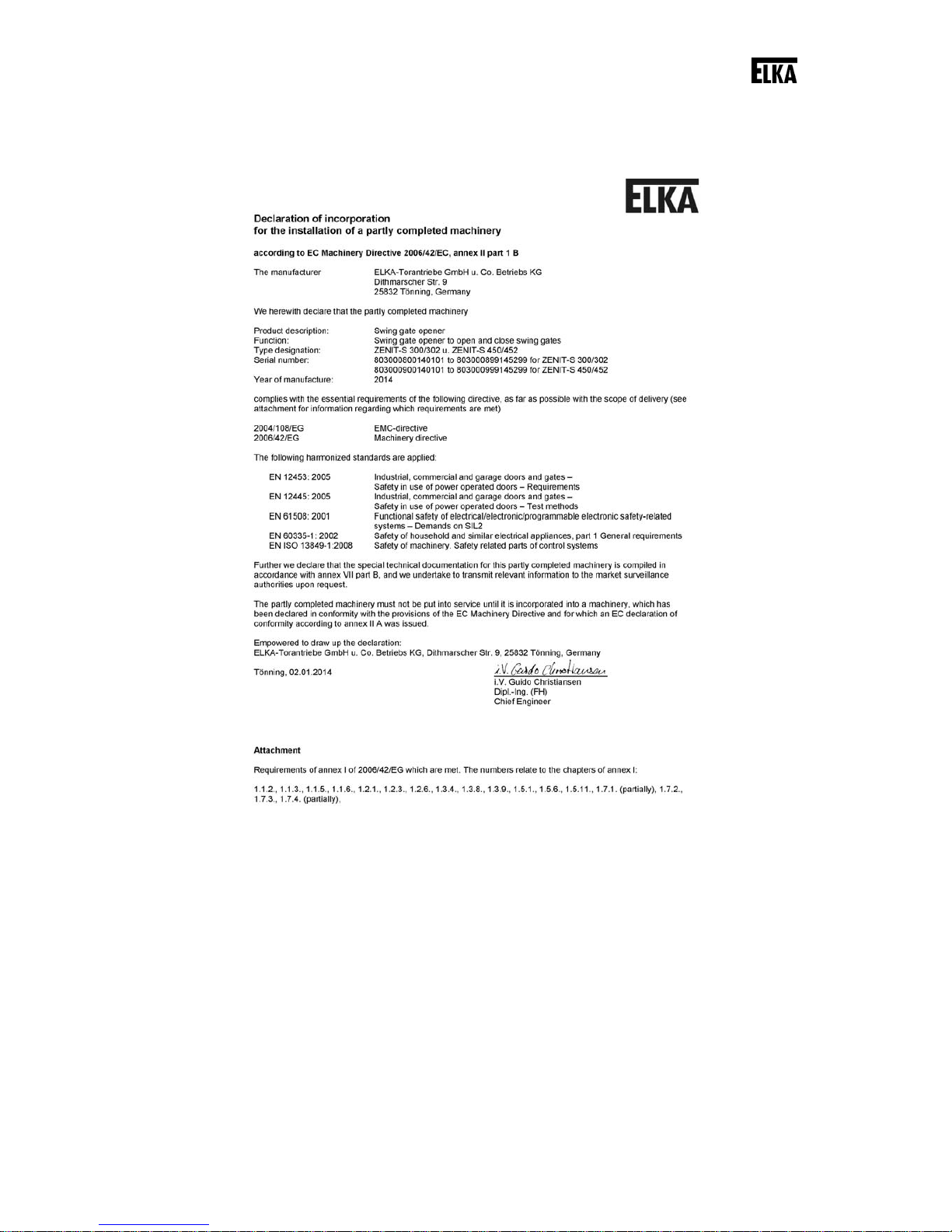
4 Declaration of incorporation
Drawing 1
Page 9
Declaration of incorporation
9
4.1 Installation information for partly completed machinery
The partly completed machinery must not be put into service until the final machinery into
which it has to be incorporated has been declared inconformity with the provisions of the
machinery directive.
The safety functions of the controller comply with EN ISO 13849-1:2008
Kat.2PL d.
According to EC Directive 2006/42/EG the mains supply has to be equipped
with an all-pole circuit breaker.
WARNING!
Danger through voltage!
Danger of an electric shock.
Only certified electricians (VDE 0100) should connect the controller to the
mains supply.
According to DIN EN 12453, for an application with passenger traffic,
depending on the type of use and type of activation, suitable safety devices
have to be installed additionally, in order to provide the minimum level of
protection.
4.2 Declaration of conformity
After installation of the gate opener, the person responsible for the installation (in accordance with DIN
EN 13241-1) has to issue - according to the directive 2006/42/EEC- a declaration of conformity for the
gate system (gate plus swing gate opener).
4.3 Nameplate
The nameplate of the swing gate opener is fitted on the fixing bracket under the hood.
Page 10

Technical data
10
5 Technical data
ZENIT-S 300/302
Gates with 1 wing / 2 wings
ZENIT-S 450/452
Gates with 1 wing / 2 wings
Max. length of wing with max. 50%
wind resistance
3.000mm / wing 4.500mm / wing
Max. surface area of wing with max.
50% wind resistance
7,50m² 10,00m²
Max . we igt h of win g
300kg 450kg
Requires electromagnetic bolt /
motor lock *
no yes
Emergency release
yes yes
Running time for 90° (per wing) **
approx. 12s approx. 12s
Max. opening angle **
120° 120°
Internal stops
yes yes
External stops required for gate
OPEN ***
no no
External stops required for gate
CLOSED ***
recommended yes
Power supply
230V / 50Hz 230V / 50Hz
Motor voltage
24Vdc 24Vdc
Duty cycle
50% 50%
Controller, separate (lxhxw)
MO 36
(175x260x100mm)
MO 36
(175x260x100mm)
Weigth incl. MO 36
approx. 17,0kg / 32,0kg approx. 17,5kg / 33,0kg
Degree of protection – gate opener
IP 44 IP 44
Degree of protection – controller
IP 44 IP 44
Temperature range
-20°C to +70°C -20°C to +70°C
Maintenance intervals
According to the applicable regulations and standards
(but at least once a year)
Table 1
* mandatory for 3,000mm and longer
** depending on the mounting dimensions
*** A perfect fixation of the gate in position OPEN and CLOSED is only possible with external
stops.
Page 11
Configuration
11
13
14
15
13
16
3
4
2
1
11
12
12
9
10
7
8
6
5
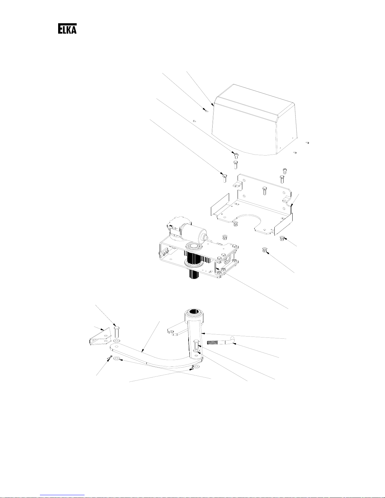
6 Configuration
Drawing 2
Page 12

Function description
12
No Quantity Name or Part
1 1 Hood
2 4 Sheet metal screw ST3,5 x 9,5
3 2 Cylinder head bolt DIN 912 – M8 x 12
4 4 Hexagon head screw DIN 933 – M8 x 25
5 1 Fixing bracket
6 4 Washer DIN 125 – A 8,4
7 4 Hexagon nut DIN 985 – M8
8 1 Operator unit
9 1 Driving lever, long version
10 1 Emergency release lever
11 1 Bolt 12 x 32
12 4 Washer DIN 125 – A 13
13 2 Eyebolt DIN 94 – 3,2 x 18
14 1 Gate support
15 1 Bolt 12 x 40
16 1 Push rod, long version
Table 2
7 Function description
The bending and straightening of the articulated arm effects the opening and closing of the gate. The
end positions are programmed in the learning sequence. During operation the gate opener shuts down
at these end positions and the mandatory mechanical end stops.
For gate wings of 3,000mm length and longer we stipulate the use of an electromagnetic bolt / motor
lock for additional blocking.
The controller MO 36 offers the possibility to activate the gate wings by radio remote control.
The controller is able to observe the max. permitted force which was set before in the learning
sequence. If during the gate movement more force is needed, the gate openers reverse. Additionally
several different safety features, e.g. photoelectric barriers and safety contact profiles, can be
connected. The safety contact profile detection (8,2kOhm) for both directions of motion is integrated in
the controller.
Page 13
Mechanical installation
13
8 Mechanical installation
8.1 Notes of safety
ATTENTION!
The controller and/or motor need to be disconnected from the gate while electric
welding is performed!
Welding can damage the controller and the motor.
Remove the controller and the gate opener from the gate/gatepost when welding work is
planned there.
REMARK!
Make sure the gate wing / wings are smooth-running and that the rotation axes are
vertical. Check if enough room for the gate opener remains, when the gate is in the end
positions.
REMARK!
Remove any interlocking system (plunger blocks etc.) or make it inoperable before the
installation of the gate.
REMARK!
All cables of the gate opener have to be laid in (protective) empty conduit according to the
application.
8.2 Required tools
Drill machine
Drill bit (stone) 12mm
Drill bit (metal) 6.8mm (8.5mm for clearance hole)
Die M8
Water level
Allen key 6mm
Flat-headed screwdriver 3mm
Crosstip screwdriver PH1
Combination wrench SW 10, SW 13, SW 17, SW 19
Measuring tape / Folding meter
8.3 Protective equipment
Safety goggles
Welding goggles
Work gloves
Page 14
Mechanical installation
14
8.4 Scobe of delivery
The scope of delivery can vary depending on the model and accessories. Please check the scope of
delivery before installation.
Openers for 1 wing Openers for 2 wings
Opener unit 1x 2x
Hood 1x 2x
Controller MO 36 1x 1x
Operating manual 1x 1x
Articulated arm 1x 2x
Emergency release key 1x 2x
Push rod 1x 2x
Gate support 1x 2x
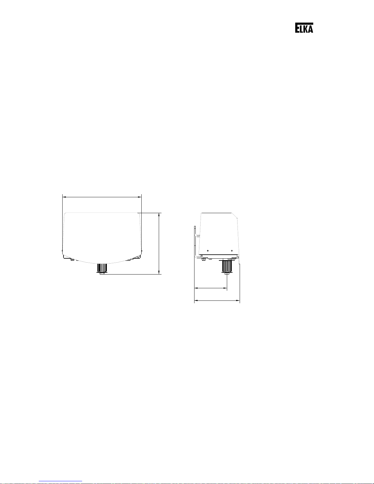
8.5 Dimensions
295
169
229
122
Drawing 3
Drawing 3 shows the housing dimensions of the gate opener.
Page 15
Mechanical installation
15
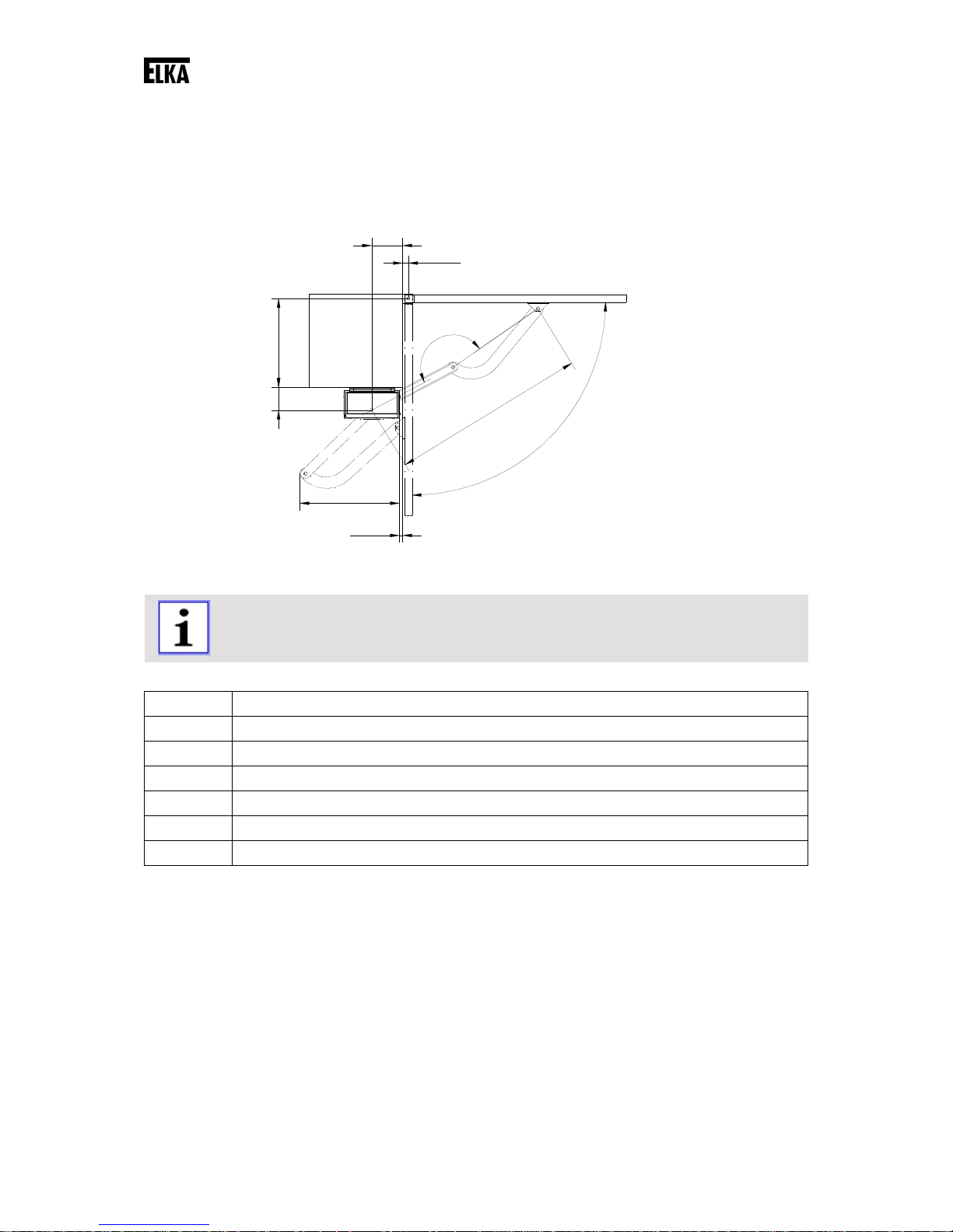
8.6 Installation dimensions
A
B
E
C
D
1
7
0
°
-
1
7
5
°
1
0
3
5
122
164
Drawing 4
REMARK!
All measurements are stated in millimetre. The gate openers are for left and right gate
wings (without alteration).
Permitted installation dimensions
A 35 to 450mm
B max. 45mm if A ≥ 400mm
B up to 80mm if A ≤ 400mm
C C = 0mm if 0° ≤ D ≤ 90°
C C up to max. 120mm if 90° ≤ D ≤ 120°
E up to max. 685mm (depending on the gate)
Table 3
Definitions:
A, B The distances “A” and “B” are related to the pivot point of the gate.
C Only when the opening angle exceeds 90°, the measurement “C” changes from
0mm up to 100mm (depending on the gate).
D Opening angle
E Required space for the articulated arm (position gate OPEN)
Page 16
Mechanical installation
16
8.7 Max. opening angle
120°
153
25
Drawing 5
Drawing 5 shows the installation dimensions for the max. opening angle.
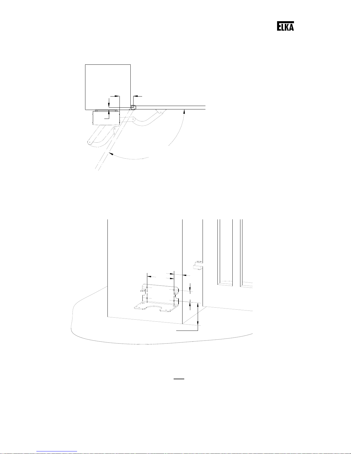
8.8 Installation at the gatepost
min. 55
180
min. 150
70
Drawing 6
Move the gate into position CLOSED.
Connect the mounting plate at the gate post using four
connection bolts (10mm diameter).
In case the gate post is made of bricks we recommend the use of special anchor bolts.
Page 17
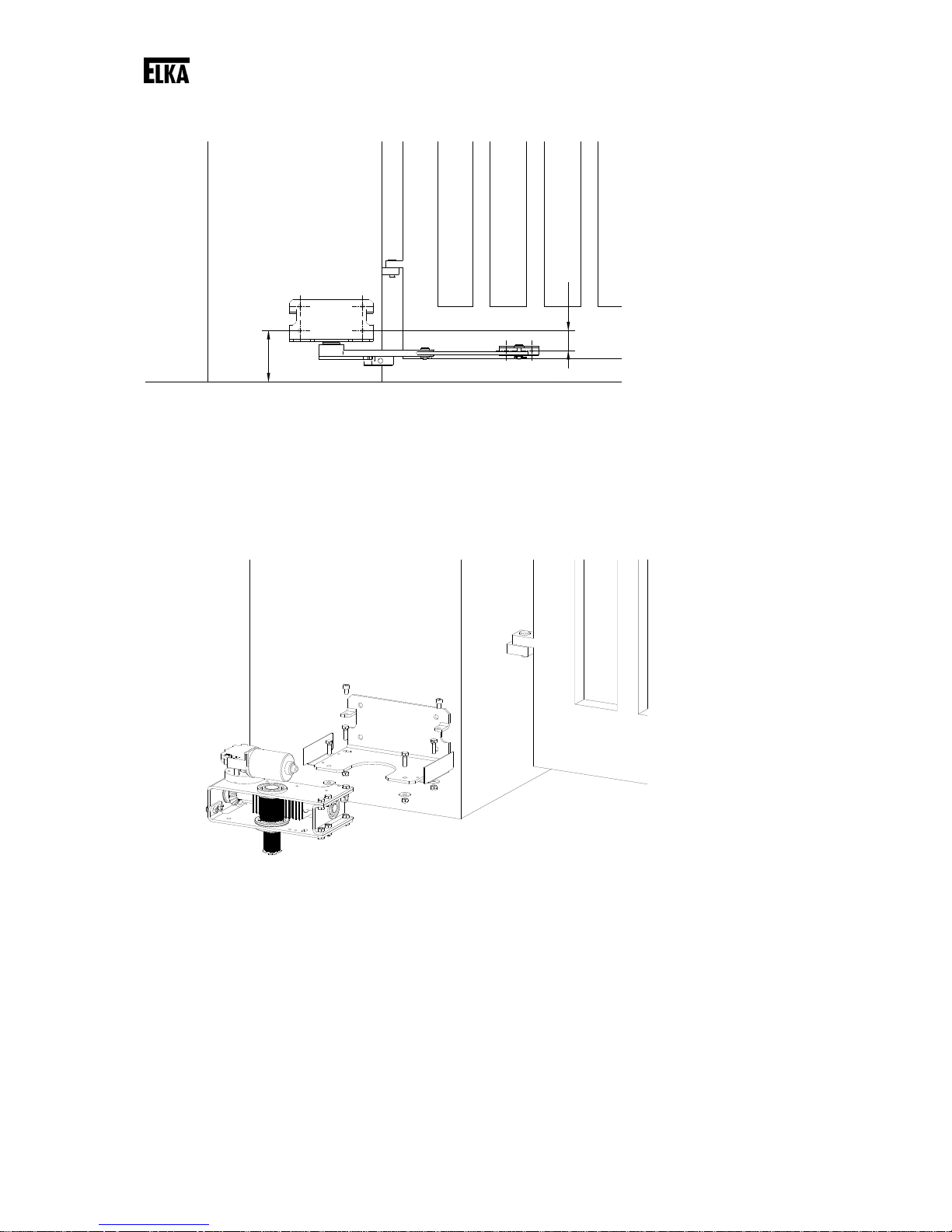
Mechanical installation
17
min. 150
58
Drawing 7
Check if with the desired installation height of the mounting plate a safe and stable installation of the
gate support at the gate leaf/ gate frame is possible. If necessary correct the installation height
upwards/downwards (see also Drawing 12).
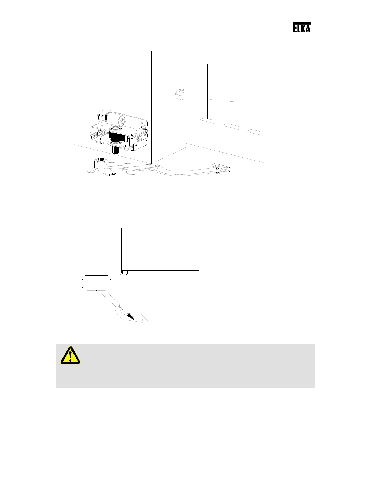
Drawing 8
First fasten the mounting plate to the gatepost and then the operator unit onto the mounting plate.
Page 18
Mechanical installation
18
Drawing 9
Mount the articulated arm on the drive shaft of the operator unit. The push rod has to point towards the
gate opening (approx.45° - see Drawing 10).
Drawing 10
WARNING!
Risk of crushing on protruding parts!
Body parts can be jammed between the upper and lower halves of the articulated arm.
Do not reach into the shear zone between the upper and lower halves of the articulated
arm.
Page 19
Mechanical installation
19
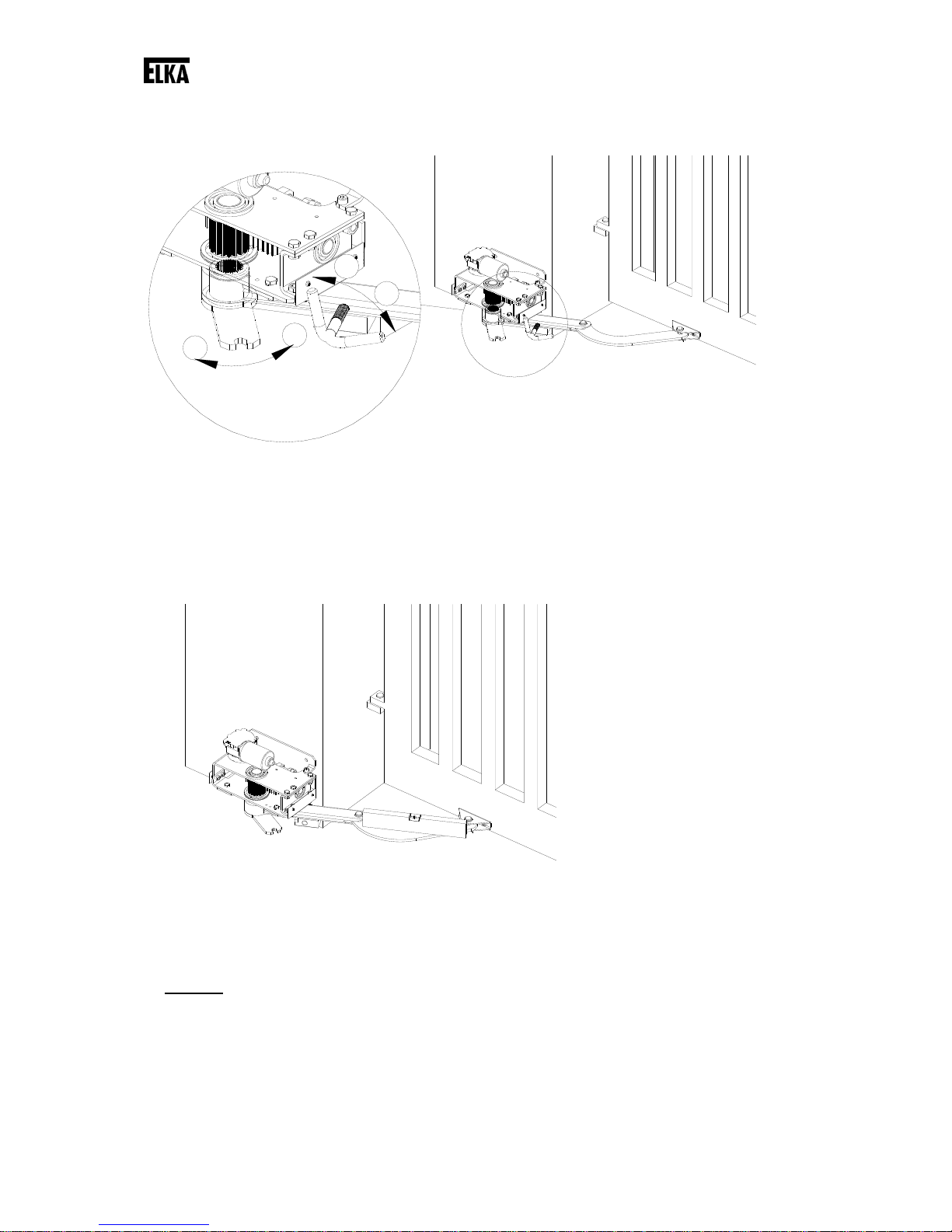
61°
61°
2
4
3
1
Drawing 11
Disengage the articulated arm using the emergency release key (see Drawing 11). To do so move the
emergency release key from position 1 to position 2. Then turn the articulated arm into the direction of
position 3, the driving lever divides itself into one upper and one lower half.
Drawing 12
Close the gate completely. Turn the articulated arm towards the gate. Align the articulated arm
horizontally.
The distance between the pivot point of the drive shaft and the pivot point of the gate support has to
be 1035mm
(see also page 15, Drawing 4).
Page 20

Mechanical installation
20
Drawing 13
REMARK!
For fastening drill and cut two M8-threads into the gate beam. Fasten the gate support
with two screws M8 x 16 (e.g. cylinder-head bolts DIN 912).
Should the material thickness not be sufficient, drill clearance holes through the gate
beam and use cylinder-head bolts in a suitable length and self-locking hexagon nuts on
the opposite gate side.
Fasten the gate support at the determined position. Then fix the articulated arm at the gate support.
Drawing 14
WARNING!
Risk of crushing!
In case the articulated arm is mounted incorrectly, the upper and lower halves can form a
shear point or crushing point.
Therefore ensure a correct installation of the articulated arm.
Page 21

Mechanical installation
21
Drawing 15
WARNING!
Risk of crushing!
Do not leave the emergency release key in the emergency release. It can form an additional
crushing point.
Remove the emergency release key after each use.
Connect the gate opener to the controller MO 36 (see also chapter 10. - Controller MO 36).
61°
61°
2
4
3
1
Drawing 16
Engage the gate opener by placing both halves of the driving lever on top of each other (turn the
upper driving lever towards position 4). Then engage the emergency release by turning the
emergency release key from position 2 towards position 1.
Page 22

Mechanical installation
22
8.9 Adjusting the internal stops
ATTENTION!
Risk of crushing!
During the next steps the gate will be moved electrically. During the adjustment the safety
devices can react differently from normal operation.
Make sure that the range of movement is free of obstacles.
REMARK!
For additional information regarding the controller see chapter 10.
a. Press the button LERN on the controller for approx. 2 seconds. The display shows p1.
b. Press the button LERN again. The display now shows 1f. Using the button BT chose
between gates with one wing (1f) and gates with two wings (2f). Confirm the choice using
button LERN. The display now shows ha.
c. Now you can move the gate wing into the end positions in slow mode. The gate wing moves
into direction OPEN only as long as button BT or BTG is pressed. Push button BT or BTG
again and the wing moves into direction CLOSED.
d. Using the button BT move the gate wing (for gates with one wing – for gates with two wings
move the main wing) into the end position OPEN. Turn the internal stop nut OPEN against the
internal stop. Fasten the internal stop nut using the counter nut.
Drawing 17
e. Using the button BT move the gate wing into the end position CLOSED. Turn the internal stop
nut CLOSED against the internal stop. Fasten the internal stop nut using the counter nut.
Counter nut
Internal Stopp nut
Internal stop
Page 23

Mechanical installation
23
Drawing 18
f. For gates with two wings move the pedestrian wing using the button BTG into the end
positions OPEN and CLOSED. Turn the internal stop nut against the internal stop and fasten
them using the counter nuts.
g. Proceed with chapter 9.4.d.
Internal stop
Internal Stopp nut
Counter nut
Page 24

Electrical installation
24
9 Electrical installation
9.1 Notes of safety
REMARK!
According to DIN EN 12453 the mains supply has to be equipped with an all-pole circuit
breaker.
ATTENTION!
Danger of short circuit or destruction by ingress of water.
Due to improper installation water can enter the controller housing.
Always install the controller housing upright, with the cable entry point on the bottom. Use
only the provided fixing points. No additional boreholes at the backside of the housing are
allowed. The cover must be mounted distortion-free. Insert the cable through the cable
entry points only.
WARNING!
Danger through voltage.
Danger of an electric shock.
Only certified electricians (VDE 0100) should connect the controller to the mains supply
(230Vac).
9.2 Installation example
Drawing 19
Page 25

Electrical installation
25
9.3 Cable connections
REMARK!
For systems with radio remote control the controller should be installed as close as
possible to the gate.
REMARK!
Connection only by fixed wiring and main switch (on site) conforming to standards. Insert
the cable only from below.
REMARK!
Please observe the minimum necessary cable cross-section [mm²], generated from the
cable length between the gate opener and the controller. A smaller gauge will have
adverse effect on the motor performance.
For the gate opener (with controller MO 36) the following cable dimensions are requested:
Cross-section: 5 x 1.5mm² up to max. 15m distance
Cross-section: 5 x 2.5mm² up to max. 20m distance
Power supply for the controller: 230Vac, 50Hz, single phase.
Connect the motor cable of the gate openers to the motor terminals (GEH and FAHR) of the controller.
REMARK!
Please use a suitable cable, possibly with a mechanical protection (conduit), for the
connection gate opener – controller. The motor cable (enclosed in shipment) is only suited
for the shortest way to the connection box. Here also allow for a mechanical protection.
REMARK!
To avoid mistakes please use marked or numbered leads within the 5-leads cable.
REMARK!
For the connection of the motor lead to the controller MO 36 use solely leads with flexible
conductors, like e.g. ÖLFLEX ROBUST 210.
Description Terminals at the MO 36
1 GND
2 IMP
3 I+
4 M5 M+
Table 4
Switch the main connection on.
Page 26

Electrical installation
26
9.4 Programming the gate opener
WARNING!
During the next steps the gate will be moved electrically!
During the programming the safety devices can react differently from normal operation.
Make sure that the range of movement is free of obstacles.
a. Press the button LERN on the controller for approx. 2 seconds. The display shows p1.
b. Press the button LERN again. The display now shows 1f.
c. Chose between gates with one wing (1f) or gates with two wings (2f) using BT. Confirm
the choice using button LERN. The display shows ha.
d. During the following step the controller learns the running distance of the gate wings. Press
the button LERN. The controller moves the gate wings into direction OPEN until it reaches the
end stop and then back into direction CLOSED until it reaches the end stop (display shows
p2).
REMARK!
The gate is now in position CLOSED. If this is not the case then the leads 4 and 5 of the
motor cable of the corresponding gate opener/s have to be interchanged at the terminals.
Then press button BTG (display shows p1), press button LERN 3 times (display shows
1f or 2f, ha and au), repeat point d.
e. Push button BT repeatedly until pp is displayed. Then confirm using button LERN.
Page 27

Controller MO 36
27
AMPEL
LSI
LSA
SLA
SLZ
BT
BTGBABZ__BS
__
VP
GND
LSI
BZ
BA
BT
BTG
STOPP
LSA
SLA
SLZ
8,2kO
8,2kO
BT
BTG
LERN
10 Controller MO 36
10.1 Fuse
The controller is protected by a fuse (3.1A slow-blow, high breaking capacity).
ATTENTION!
Replace the fuse on the controller with equivalent types only.
Fuse type: T3.1A H250V or T3A1H250V
10.2 Input terminals of the controller
Drawing 20
Mark Connection Function
LSI LSI + GND Photoelectric barrier contact INSIDE
GND Mutual ground for LSI and LSA
LSA LSA + GND Photoelectric barrier contact OUTSIDE
SLA SLA + GND Safety contact profile OUTSIDE (8.2kOhm-resistance)
SLI SLI + GND Safety contact profile INSIDE (8.2kOhm-resistance)
BT BT + GND Push button for complete opening
BTG BTG + GND Push button for partial opening
BA BA + GND Push button OPEN
BZ BZ + GND Push button CLOSE
GND Mutual ground for BT, BTG, BA, and BZ
GND Ground for BS
BS BS + GND Push button STOP
Table 5
Page 28

Controller MO 36
28
phot-cell outside LSI
transmitter 2-6
receiver 1
transmitter 1receiver 1
24V 0V
1k0
24V 0V
1k0
photo-cell inside LSA
receiver 2-6
24V 0V
1k0
24V 0V
1k0
transmitter 2-6
receiver 1
24V 0V 24V 0V
24V 0V 24V 0V
transmitter 2-6
AMPEL
BTG
LERN
BT
10.2.1 Photoelectric barrier connection
Drawing 21
REMARK!
In case the inputs LSA, LSI, or BS are not required, they have to be linked to a jumper.
REMARK!
The direct current supply 24Vdc and 12Vdc can be used for a total of max. 300mA.
The controller provides two inputs for photoelectric barriers for optical protection.
Connect the photoelectric barriers for outside of the gate to the LSA, and for inside of the gate to LSI.
The green LEDs LSI and LSA show the status of the photoelectric barriers. When a photoelectric
barrier is interrupted, the corresponding LED lights.
Page 29

Controller MO 36
29
10.2.2 Safety contact profile
REMARK!
Each safety contact profile terminal SLA and SLZ which is not used has to be linked to an
8.2kOhm resistor.
REMARK!
In case a safety function leads to switching-off, with a system with two wings always both
motors switch off.
The controller is equipped with two integrated detectors (with testing function according to EN954-1
category 2) for safety contact profiles with resistance detection to secure the closing edges in direction
OPEN and CLOSED.
The red LEDs SLA and SLZ show the status of the safety contact profiles. When the safety contact
profile is activated, the corresponding LED lights.
Direction of
Action of SLA Action of SLZ
Stop, gate shall open
Gate can only open in emergency
-
Stop, gate shall close -
Gate can only close in emergency
mode
Gate wing opens
Stop and reversing for a short
distance
-
Gate wing closes - Stop and reversing
Table 6
REMARK!
Counting function:
When the gate makes contact with an obstacle and the safety contact strip SLZ activates
the reversing function, the gate opens.
In case the automatic closure is activated and the obstacle does not get removed, a
constant closing by automatic closure and reversing by the obstacle could occur.
To prevent this, a counting function is provided. After 2 tries to close by automatic
closure only a reversing for a short distance occurs. The counter is cleared when the gate
is operated manually.
Page 30

Controller MO 36
30
safety contact
profile for gate
OPEN
safety contact
profile for gate
CLOSE
8,2kOhm
8,2kOhm
safety contact
profile for gate
OPEN
safety contact
profile for gate
CLOSE
GND
SLZ
SLA
MO36
Connection plan:
Drawing 22
REMARK!
Several safety contact profiles with 8.2kOhm load resistance can be set-up in serial
connection. The safety category remains the same.
REMARK!
Make sure to check the function of the safety contact profiles by activating each single
one manually. The corresponding LED (SLZ or SLA) has to light red.
REMARK!
Observe the effective direction oft he safety contact profiles. The profiles which react in
direction CLOSE have to be connected to the input terminal SLZ. The profiles which react
in direction OPEN have to be connected to the input terminal SLA.
Page 31

Controller MO 36
31
main wing (or 1-winged
gates) with 24Vdc motor with
pulser
LS-Test
12Vdc
24Vdc
GND
BT
BTG
AMPEL
WARN 230Vac/max. 60W
MULTI 230Vac/max. 60W
LERN
magnetic lock 24Vdc/max 1A
electromagnetic bolt 24Vdc/max 1A
pedestrian wing with 24Vdc
motor with pulser
LSI
LSA
SLA
SLZ
BT
BTGBABZ__BS
__
VP
10.3 Output terminals of the controller
Drawing 23
Mark Connection Function
SCHL SCHL + GND Connection for magnetic clamp (24Vdc, max. 1A)
GND Mutual ground for magnetic clamp and electromagnetic bolt
SCHL SCHL + GND Connection for electromagnetic bolt (24Vdc, max. 1A)
GEH: 5-polig Motor connection pedestrian wing
FAHR: 5-polig Motor connection main wing
MULTI 2-polig
Potential-free contact for multi-functional relay (230Vac, max.
WARN 2-polig Potential-free contact for warning light (230Vac, max. 60W)
GND Mutual ground 12V, 24V, and LS-TST
24V 24V + GND 24Vdc, stabilised (altogether with 12Vdc max. 300mA)
12V 12V + GND 12Vdc, stabilised (altogether with 24Vdc max. 300mA)
LS-TST LS-TST + GND Photoelectric barrier testing (24Vdc for transmitter)
Table 7
REMARK!
The ground of the direct current supply 24Vdc/12Vdc is connected to the controller
ground.
Page 32

Controller MO 36
32
LERN
BTG
BT
BA
SLA
LSA
LSI
BTG
SLZ
BT
__
VP
__
BS
BZ
AMPEL
10.4 Buttons on the controller
BT
BTG
AMPEL
LERN
LSI
LSA
SLA
SLZ
BT
BTGBABZ__BS
__
VP
MO 36
BA
BTG
BT
SLZ
SLA
LSA
LSI
LERN
BT
BTG
Drawing 24
Mark Function Remark
BT Button for complete opening Same function as external button BT
BTG Button for partial opening Same function as external button BTG
LERN Learn button
Table 8
10.5 LEDs on the controller
Drawing 25
Page 33

Controller MO 36
33
Mark Colour Function
Normal
LSI green
Lights when photoelectric barrier INSIDE is
interrupted
OFF
LSA green
Lights when photoelectric barrier OUTSIDE is
interrupted
OFF
SLA red Lights when safety contact profile OPEN is activated OFF
SLZ red
Lights when safety contact profile CLOSED is
activated
OFF
BT green
Lights when button BT (internal or external) is
activated
OFF
BTG green
Lights when button BT (internal or external) is
activated
OFF
BA green Lights when button BA is activated OFF
BZ green Lights when button BZ is activated OFF
BS green
Lights when button BS is NOT activated (BS-contact
n.c.)
ON
Vp yellow Lights when connected to supply voltage ON
Display red 2 x 7-segment display ( 88 ) OFF
Table 9
10.6 Clip-on module
10.6.1 Clip-on timer module ASU2 (optional)
The controller provides a socket for the timer module ASU2.
The timer has the following function:
When the timer is activated it works like an OPEN command. The gate cannot be closed as long as
the timer is activated.
When the timer is deactivated it works like a CLOSE signal. When the timer sends the CLOSE
command, the gate is closed immediately even when automatic closure is activated.
REMARK!
Do not connect anything but the optional module ASU2 at the terminal ASU2 on the
controller MO 36.
Page 34

Controller MO 36
34
red traffic light 230Vac
green traffic light 230Vac
traffic module
AMO34A
230Vac
AMPEL
10.6.2 Traffic light module AMO34A (optional)
Drawing 26
Status Red traffic light Green traffic light
Gate is completely open Off On
Gate is moving
OR
Gate is in an intermediate position
OR
Gate is closed
On Off
Table 10
REMARK!
Do not connect anything but the optional module AMO34A at the terminal AMPEL on the
controller MO 36.
Page 35

Controller MO 36
35
10.7 Programmin controller MO 36
WARNING!
During the programming the safety devices can react differently from normal operation.
Make sure that no person is present within the danger zone during programming.
REMARK!
At least the following sequences have to be learned as basic configuration:
P1 - Learning of running distance
P2 - Adjusting of force and speed
PP - Saving of data
REMARK!
In the learning sequence the swing gate opener can be adjusted according to the
requirements, e.g. to the type of use.
To program the controller and to set the parameters the controller provides a two-digit 7-
segment-display and the buttons BT, BTG, and LERN.
During normal operation the display is off. The learning sequence is activated by
pushing the button LERN for approx. 2s. The display shows p1. The sequence 1 is
preset.
With the button BT you can move on to the next sequence p2, p3 etc. With the button
BTG you can move back to the last sequence.
When the required sequence is displayed, it has to be activated by button LERN.
When the sequence pp is selected and confirmed by button LERN, the parameters are
saved and then returned to regular mode.
Page 36

Controller MO 36
36
The learning sequence
Sequence Function
p1
Selecting one wing operation / two wings operation
Adjusting of end stops
Learning of safety contact profiles and photoelectric barriers connected
Learning the running distance
p2
Adjusting of force and speed
p3
Adjusting of time lag of the pedestrian wing after the main wing during closing.
p4
Adjusting of time lag of the main wing after the pedestrian wing during opening.
p5
Learning the radio remote control codes for BT, BTG, and MULTI
Deleting the radio remote control codes for BT, BTG, and MULTI
p6
Activating / deactivating automatic closure for both wings, changing stay-open time.
p7
Activating / deactivating automatic closure for pedestrian wing, changing stay-open
time.
p8
Selecting of warning prior to opening and closing
p9
Selecting of photoelectric barrier function
pa
Activating / deactivating photoelectric barrier testing
pb
Activating / deactivating lockage function for photoelectric barrier
pc
Selecting pressure relief of electromagnetic bolt
pd
Selecting wind blast suppression
pe
Selecting mode of multi-functional relay
pf
Return to original settings
pp
Saving of data and returning to regular mode
Table 11
Page 37

Controller MO 36
37
10.7.1 Sequence p1: Learning the running distance
Selecting system with 1 wing / system with 2 wings
Display Function
1f
To operate gates with one wing.
2f
To operate gates with two wings.
Tabelle 1
Confirm the selection with button LERN.
Then ha (manual operation) is displayed. The gate wings now can be operated in manual operation
to adjust the internal mechanical end stops inside the gate openers. Button BT is used for the main
wing and BTG for the pedestrian wing in dead man’s mode. The first direction is always OPEN.
REMARK!
After adjustment of the end stops the wings should not be in either end position but at
least 50cm away, because the first movement goes into direction OPEN.
WARNUNG!
Risk of crushing by an automatic movement of the gate wings!
Individuls or objects within the danger area of the gate could get injured or damaged
respectively by the gate movement.
Ensure that no individuals or objects reside o rare present within the danger area during
the learning process.
REMARK!
After the next confirmation by button LERN the gate moves automatically.
Confirm the adjustment of the end stops using the button LERN.
Then au (automatic mode) is displayed. The controller tests the safety contact strips and the
photoelectric barriers. Then the gate moves automatically and learns the running time.
REMARK!
Only when this photoelectric barrier testing was successful, additional tests can be carried
out during future operation.
Page 38

Controller MO 36
38
Gates with one wing: During learning of the running time the wing first opens and then closes. The
wing stops at the end stop by force control.
Gates with two wings: During learning of the running time the pedestrian wing opens first, then the
main wing opens, the main wing closes, and at last the pedestrian wing
closes. The wings stop at the end stops by force control.
REMARK!
During the learning of the running time the pressure relief of the electromagnetic bolt is
not in function. During learning of the distance the electromagnetic bolt is being activated
during each wing movement. Then returning to the main sequence follows automatically.
10.7.2 Sequence p2: Adjusting of force and speed
The force and speed can be adjusted for each wing and for opening and closing separately. When
sequence p2 is activated by button LERN an additional selection menu for force values and speed
values (f1, f2, etc.) opens. Use button BT to move to the next selection menu point.
Selection Selection menu points for force and speed
Sub-sequence Function
f1
Force to open the main wing
f2
Force to close the main wing
f3
Force to open the pedestrian wing. No function with gates with one wing.
f4
Force to close the pedestrian wing. No function with gates with one wing.
s1
Speed to open the main wing
s2
Speed to close the main wing
s3
Speed to open the pedestrian wing. No function with gates with one wing.
s4
Speed to close the pedestrian wing. No function with gates with one wing.
Table 12
User button LERN to activate the desired selection menu point. The present value for force (f for
force) or speed (s for speed) is displayed. Possible values are 01 (for minimum force) up to 99 (for
maximum force) or 01 (for minimum speed) up to 08 (for maximum speed). With button BT the
values may be increased, with button BTG they can be decreased. Confirm the current selection and
return to the selection menu or to the main learning sequence using button LERN.
WARNING!
In the learning sequence a force value (f1 – f4) for the motor current is selected.
Therefore the operator is responsible that only a permitted force value is set (see Table 14).
Gate opener Setting range in the learning sequence
ZENIT-S 300 / 302 f1 – f4 = max. 55
ZENIT-S 450 / 452 f1 – f4 = max. 65
Table 13
Page 39

Controller MO 36
39
10.7.3 Sequence p3: Time lag of the pedestrian wing during closing
When sequence p3 is activated by button LERN, the present value for the time lag of the pedestrian
wing during closing is displayed.
Possible values are 00 (for 0 seconds) up to 09 (for seconds).
The value can be increased using button BT, and decreased using button BTG. To return to the
learning sequence use button LERN.
REMARK!
When a time lag is selected for gates with one wing, it will not be in effect.
10.7.4 Sequence p4: Time lag of the main wing during opening
When sequence p4 is activated by button LERN, the present value for the time lag of the main wing
during opening is displayed.
Possible values are 00 (for 0 seconds) up to 09 (for seconds).
The value can be increased using button BT, and decreased using button BTG. To return to the
learning sequence use button LERN.
REMARK!
When a time lag is selected for gates with one wing, it will not be in effect.
Page 40

Controller MO 36
40
10.7.5 Sequence p5: Learning and deleting of radio remote control codes
When sequence p5 is activated by button LERN, a selection menu is displayed to select the radio
remote control code. Use button BT to move to the next selection menu point.
Selection
Selection menu points for radio remote control
Sub-sequence Function
c1
Radio remote control code for BT can be learned or deleted.
c2
Radio remote control code for BTG can be learned or deleted.
c3
Radio remote control code for MULTI can be learned or deleted.
Return to (main) learning sequence
Table 14
The desired sub-sequence is activated by button LERN. The display shows:
Display Corresponds to
- - The code for the selected radio remote control channel is deleted and another
can be learned.
oo
The code for the selected radio remote control channel is already stored and can
be overwritten or deleted.
Table 15
To learn a radio remote control code the (already coded) transmitter has to be operated. Then the
code will be stored and return to the sub-sequence follows.
Deleting radio remote control code:
To delete the radio remote control code, press and hold the button BT and additionally push the button
LERN. The radio remote control code is deleted and return to the sub-sequence follows.
If only the button LERN is pushed, then return to the sub-sequence follows without changing the code.
Radio remote control display:
The decimal dot at the ones-column on the display is lit, when a stored code signal is received.
Page 41

Controller MO 36
41
10.7.6 Sequence p6: Automatic closure for complete opening
When using automatic closure both wings close automatically after the learned stay-open time has
elapsed.
The stay-open time starts elapsing when the last wing has reached the position OPEN.
When sequence p6 is activated by button LERN, the present value for stay-open time for complete
opening is displayed. The display shows - - when automatic closure is deactivated.
Using button BT automatic closure can be activated and the value can be increased. To decrease
the value and to deactivate automatic closure use button BTG.
The stay-open time can be set from 1s up to 299s. The decimal dots of the display are each equal to
100s. The right decimal dot stands for 100s, the left one for 200s.
Example Correspond to
--
Automatic closure is not activated.
23
Automatic closure is activated. The stay-open time is 23 seconds.
23.
Automatic closure is activated. The stay-open time is 123 seconds.
2.3.
Automatic closure is activated. The stay-open time is 223 seconds.
Table 16
REMARK!
Counting function:
When the gate makes contact with an obstacle and the safety contact strip SLZ activates
the reversing function, the gate opens.
In case the automatic closure is activated and the obstacle does not get removed, a
constant closing by automatic closure and reversing by the obstacle could occur.
To prevent this, a counting function is provided. After 2 tries to close by automatic
closure only a reversing for a short distance occurs. The counter is cleared when the gate
is operated manually.
When the stay-open time has elapsed and the safety contact profile SLZ is activated, the
gate remains open. The elapsed stay-open time will not be repeated. When the safety
contact profile SLZ is not activated anymore and the stay-open time has elapsed, the
warning time prior to closing starts.
When BS is activated, the automatic closure function is blocked and no automatic closure
occurs.
A blocked automatic closure is unblocked by an open command.
When the lockage function is active, the automatic closure is blocked as long as an
obstacle is present between the photoelectric barriers.
Page 42

Controller MO 36
42
10.7.7 Sequence p7: Automatic closure for pedestrian wing
When using automatic closure the pedestrian wing closes automatically after the learned stay-open
time has elapsed.
The stay-open time starts elapsing when the wing has reached the position OPEN.
When sequence p7 is activated by button LERN, the present value for stay-open time for the
pedestrian wing is displayed. The display shows - - when automatic closure is deactivated.
Using button BT automatic closure can be activated and the value can be increased. To decrease
the value and to deactivate automatic closure use button BTG.
The stay-open time can be set from 1s up to 299s. The decimal dots of the display are each equal to
100s. The right decimal dot stands for 100s, the left one for 200s.
Example Corresponds to
--
Automatic closure is not activated.
23
Automatic closure is activated.
The stay-open time is 23 seconds.
23.
Automatic closure is activated.
The stay-open time is 123 seconds.
2.3.
Automatic closure is activated.
The stay-open time is 223 seconds.
Table 17
REMARK!
Counting function:
When the gate makes contact with an obstacle and the safety contact strip SLZ activates
the reversing function, the gate opens.
In case the automatic closure is activated and the obstacle does not get removed, a
constant closing by automatic closure and reversing by the obstacle could occur.
To prevent this, a counting function is provided. After 2 tries to close by automatic
closure only a reversing for a short distance occurs. The counter is cleared when the gate
is operated manually.
When the stay-open time has elapsed and the safety contact profile SLZ is activated, the
gate remains open. The elapsed stay-open time will not be repeated. When the safety
contact profile SLZ is not activated anymore and the stay-open time has elapsed, the
warning time prior to closing starts.
When BS is activated, the automatic closure function is blocked and no automatic closure
occurs.
A blocked automatic closure is unblocked by an open command.
When the lockage function is active, the automatic closure is blocked as long as an
obstacle is present between the photoelectric barriers.
Page 43

Controller MO 36
43
10.7.8 Sequence p8: Pre-warning
The warning light is only active, when a gate wing is moving or during warning prior to opening and
closing. Otherwise the warning light is not active.
Display Pre-warning before opening Pre-warning before closing
00
No warning time No warning time
04
No warning time 4 seconds warning time
40
4 seconds warning time No warning time
44
4 seconds warning time 4 seconds warning time
Table 18
REMARK!
When using the gate opener in connection with the electromagnetic bolt E 205, motor lock
M315, or with a magnetic clamp (on site) the pre-warning time must be activated.
Page 44

Controller MO 36
44
10.7.9 Sequence p9: Photoelectric barrier function
When sequence p9 is activated by button LERN, the present value for photoelectric barrier function is
displayed. Using button BT the desired operating mode can be selected.
To confirm the selection and to return to the learning sequence use button LERN.
Drawing 27
LS-Function
Photoelectric
barrier
Gate not moving Gate opens Gate closes
L1 LSI
Remains not
moving
Stops, opens
when free again
Stop, opens when
free again
LSA
Remains not
moving
Stop, opens
when free again
Stop, opens when
free again
L2 LSI
Remains not
moving
Stop, opens
when free again
Stop, closes when
free again
LSA
Remains not
moving
Stop, opens
when free again
Stop, closes when
free again
L3 LSI
Only closing
allowed
Stop, opens
when free again
No effect
LSA
Only opening
allowed
No effect
Stops and opens
immediately
Table 19
Page 45

Controller MO 36
45
phot-cell outside LSI
transmitter 2-6
receiver 1
transmitter 1receiver 1
24V 0V
1k0
24V 0V
1k0
photo-cell inside LSA
receiver 2-6
24V 0V
1k0
24V 0V
1k0
transmitter 2-6
receiver 1
24V 0V 24V 0V
24V 0V 24V 0V
transmitter 2-6
AMPEL
BTG
LERN
BT
10.7.10 Sequence pa: Photoelectric barrier testing
When sequence pa is activated by button LERN, the present operating mode is displayed. Using
button BT the desired operating mode can be selected. To return to the learning sequence use button
LERN.
Display Corresponds to
of
Photoelectric barrier testing not activated.
on
Photoelectric barriers, which have passed the test during the programming of the
running distances for the wings, are also being tested during normal operation.
Table 20
Prior to every gate movement a photoelectric barrier test may be performed. The test consists of two
phases. During the first phase the supply of the transmitters is switched off. The controller waits for the
receiver to report an obstacle within the next 2.5s. No the second phase begins. During the second
phase the supply of the transmitter is switched on again. The controller expects the receiver to report
no obstacle anymore. Only after this procedure the gate starts to move. If an error occurs during the
first phase, the photoelectric barrier is faulty. An error message is issued. If an error occurs during the
second phase, the controller interprets this as a real obstacle and the gate will not move. No error
message is issued. You can connect and test 6 photoelectric barriers each for LSA and LSI with the
controller MO 36. All relay outputs of the receivers are switched in serial connection. Parallel to the
relay contacts of each receiver you must add a 1kOhm +/- 5% resistor.
Drawing 28
REMARK!
During the learning of the running distances the controller performs a photoelectric barrier
testing and learns if and how many photoelectric barriers are connected. If the
photoelectric barrier testing as successful, tests can also be done later during normal
operation. In case the test during the leaning phase was not successful, no photocell
testing will occur later during normal operation.
Page 46

Controller MO 36
46
REMARK!
After the learning the operator has to check each photoelectric barrier for functioning.
REMARK!
When a faulty photoelectric barrier is detected during the testing or when an obstacle is
present within the photoelectric barrier, the gate can be opened and closed in emergency
mode.
10.7.11 Sequence pb: Lockage function of the photoelectric barriers
Drawing 29
A lockage function by photoelectric barriers is possible in connection with the automatic closure. To
activate this function use the learning sequence.
The lockage function is only activated when the gate is open.
When the gate reaches the end position OPEN, the lockage function is initialised, which means it is in
its initial state “Automatic closure by lockage function approved”.
When a vehicle first passes the photoelectric barrier LSA and then the photoelectric barrier LSI, then
the interruption of LSA blocks the automatic closure and the interruption of LSI unblocks it and starts
the stay-open time. When driving in the opposite direction, the blocking and unblocking occur
accordingly.
When sequence pb is activated by button LERN, the present selection is displayed. With button BT
the desired value can be selected. To return to the learning sequence use button LERN.
Display Corresponds to
of
Lockage function ist deactivated.
on
Lockage function is activated. When automatic closure is activated, a closing of
the gate wing / wings is only possible, after an incoming or outgoing vehicle has
passed both
(LSA and LSI) photoelectric barriers.
Table 21
Page 47

Controller MO 36
47
10.7.12 Sequence pc: Pressure relief for electromagnetic bolt
When sequence pc is activated by button LERN, the present selection is displayed. With button BT
the desired value can be selected. To return to the learning sequence use button LERN.
Display Corresponds to
s1
Pressure relief for electromagnetic bolt is deactivated.
s2
The gate wing pushes in slow mode min. 500ms, but max. 1.000ms, against the
end stop, until the selected force value is passed.
s3
The gate wing pushes in slow mode min. 500ms, but max. 2.000ms, against the
end stop, until the selected force value is passed.
s4
The gate wing pushes in slow mode min. 500ms, but max. 90s, against the end
stop, until the selected force value is passed.
Table 22
10.7.13 Sequence pd: Wind blast suppression
WARNING!
Risk of crushing!
Activation of the wind blast suppression results in a delayed reaction on obstacle.
Use the wind blast suppression only, when additional devices like photoelectric barriers or
safety contact profiles are installed at the gate.
It can be chosen to either reverse on obstacle immediately, or to reverse after the selected threshold
value is exceeded for a preset time. A short wind blast or a swinging gate wing do not result in a
reversing.
REMARK!
The selected wind blast suppression time has no effect at the end position.
When sequence pd is activated by button LERN, the present selection is displayed. With button BT
the desired value can be selected. To return to the learning sequence use button LERN.
Display Corresponds to
u-
No wind blast suppression. The controller immediately reacts on obstacle.
u1 up to u9 The wind blast suppression is equal to 1s (for u1) up to 9s (for u9).
The controller reacts on obstacle only, if detected longer than 1s (for u1) up to
9s (for u9).
Table 23
Page 48

Controller MO 36
48
10.7.14 Sequence pe: Multi-function relay
The multi-functional relay on the controller is suitable for different modes. For the selection use the
learning sequence.
When sequence pe is activated by button LERN, the present selection is displayed. With button BT
the desired selection can be chosen. To return to the learning sequence use button LERN.
REMARK!
During the learning function of the controller the relay is inactive.
Display Corresponds to
r1
Push button mode:
The relay is active, as long as the radio remote control code MULTI is received.
r2
Toggle mode: The relay alternates between active and inactive with each
received radio remote control code MULTI.
r3
Light pulse mode:
The relay is active for 1 second, when BT, Funk BT, BTG, Funk BTG, BA, or BZ
are pushed.
r4
3-minute-light:
The relay is active for 180 second, when BT, Funk BT, BTG, Funk BTG, BA, or
BZ are pushed.
Table 24
10.7.15 Sequence pf: Return to origgnal setting
When sequence pf is activated by button LERN, rE is displayed.
To return to original settings press and hold button BT and push button LERN.
If only button LERN is pushed, you return to the learning sequence without changing any values. After
returning to original settings the running distance has to be relearned.
10.7.16 Sequence pp: Storing of data
When sequence pp is activated by button LERN, the implemented selections and changes are saved
power-failure-safe.
Automatic return from learning sequence to normal operation follows. The display turns off.
Page 49

Normal operation
49
11 Normal operation
Gate movement OPEN
1. The electromagnetic bolt is activated (magnetic clamp is deactivated). If pressure relief for
electromagnetic bolt is activated, the gate moves against the end stop, to relief the pressure.
2. Then the gate wing accelerates continuously until the selected end speed is reached. With
this speed the gate wing moves until a short distance before the end position OPEN. There
the speed is decelerated and the gate wing moves in slow mode against the end stop.
3. The electromagnetic bolt is deactivated (magnetic clamp is activated).
Gate movement CLOSED
1. The electromagnetic bolt is activated (magnetic clamp is deactivated). If pressure relief for
electromagnetic bolt is activated, the gate moves against the end stop, to relief the pressure.
2. Then the gate wing accelerates continuously until the selected end speed is reached. With
this speed the gate wing moves until a short distance before the end position CLOSED.
There the speed is decelerated and the gate wing moves in slow mode against the end stop.
3. The electromagnetic bolt is deactivated (magnetic clamp is activated).
Stop and restarting in an intermediate position
1. The gate stops and the electromagnetic bolt is deactivated (magnetic clamp is activated).
2. The opening and closing from an intermediate position proceeds similar to the normal
opening and closing, only without pressure relief of the electromagnetic bolt.
11.1 Operation with push button
1. BA is for function OPEN. As long as BA is pushed, the gate cannot close.
2. BZ is for function CLOSE.
3. BS is for function STOP. As long as BS is pushed (contact BS is interrupted), no gate
movement is possible. Automatic closure is disabled by BS. When BS is released, a new
operating command has to be given.
4. BT (internal, external, or Funk-BT) is for function OPEN-STOP-CLOSE-STOP, depending on
the present gate position or gate movement. For gates with 1 wing the main wing, for gates
with 2 wings the main and the pedestrian wing are activated.
5. BTG (internal, external, or Funk-BTG) is for function OPEN-STOP-CLOSE-STOP,
depending on the present gate position or gate movement. For gates with 2 wings the
pedestrian wing is activated. For gates with 1 wing the button BTG has no function during
normal mode.
11.2 Operation with push button and automatic closure for both wings
1. BT (internal, external, or Funk-BT) is for function OPEN. During gate movement BT is
without function. In position OPEN BT is for function CLOSE.
2. BTG (internal, external, or Funk-BTG) is for function OPEN-STOP-CLOSE-STOP for the
pedestrian wing.
3. BA is for function OPEN. As long as BA is pushed, the gate cannot close.
4. BZ is for function CLOSE.
5. As long as BS is pushed (contact BS is interrupted), no gate movement is possible.
Automatic closure is disabled by BS. When BS is released, a new operating command has
to be given.
Page 50

Normal operation
50
11.3 Operation with push button and automatic closure fort he pedestrian wing
1. BTG (internal, external, or Funk-BT) is for function OPEN for the pedestrian wing. During the
gate movement BTG is without function. In position OPEN BTG is for function CLOSE.
2. BS is for function STOP. As long as BS is pushed (contact BS is interrupted), no gate
movement is possible. Automatic closure is disabled by BS. When BS is released, a new
operating command has to be given.
11.4 Emergency release during power failure
REMARK!
Use the emergency release only to mechanically disengage the gate from the gate opener
in case of power failure.
11.4.1 Disengaging the gate opener
WARNING!
Risk of crushing on protruding parts!
Body parts can be crushed between upper and lower half of the articulated arm.
Do not reach between or onto the upper or lower half of the articulated arm.
61°
61°
2
4
3
1
Drawing 30
Now disengage the articulated arm using the emergency release key (see Drawing 29). To do so
move the emergency release key from position 1 to position 2. Then turn the articulated arm towards
position 3; the driving lever is divided in an upper and a lower part.
WARNING!
Risk of crushing!
Do not leave the emergency release key in the keyhole. It could form another crushing
point. Remove the emergency release key after each use.
Page 51

Normal operation
51
11.4.2 Engaging the gate opener
61°
61°
2
4
3
1
Drawing 31
Engage the gate opener by moving both parts of the push rod back one upon the other (turn the upper
part towards position 4). Then engage the emergency release by turning the emergency release key
from position 2 to position 1.
11.5 Power failure
After the power supply is switched on and after each power failure the current position of the gate
wings is unknown. The controller first operates in a starting mode, and the gate openers move in slow
mode.
When the gate stops in the end position CLOSED (The main wing for gates with one wing also in the
end position OPEN), the gate position is known and the controller switches to normal mode.
Before every movement a pressure relief for the electromagnetic bolt occurs and the wings close one
after the other. During staring mode using the emergency mode is possible.
Page 52

Normal operation
52
11.6 Emergency mode
In case a safety device LSA, LSI, SLA, or SLZ is faulty, emergency mode is possible. After a warning
time of 10 seconds, the gate can be moved in an emergency mode by using BA or BZ (dead man’s
function). During the warning time as well as during the emergency mode the waning light is flashing.
Emergency mode by radio remote control (BT or BTG) is not possible due to safety reasons.
After the power is switched on the gate position is not known, Emergency mode is possible during
starting mode after power is switched on but only the slow mode is available and the gate wings close
one after the other.
ATTENTION!
The use of signal generators, which are issuing a signal of more than 2
seconds duration (e.g. timers, induction loop detectors, key switches, radio
remote control receivers) is prohibited. Otherwise the installation works in
dangerous operation, when a safety device fails.
WARNING!
Risk of crushing!
Even when a safety device is faulty the gate can be moved using BA and BZ.
The buttons BA and BZ therefore have to be installed in such a way, that the gate can be
seen during movement.
WARNING!
Risk of crushing!
In case the multi-functional relay is used for an additional radio remote control channel
connected to BA or BZ, the emergency mode can be started by radio remote control.
In this case only fixed transmitters should be used in such a way, that the gate can be seen
during movement from the location of the transmitter.
WARNING!
Risk of crushing!
Are external devices, which give a constant signal, connected to BA or BZ, these devices
can start the emergency mode and move the gate when a safety device is faulty or
activated.
Page 53

Fault diagnosis
53
12 Fault diagnosis
An fault is shown on the display as a code, when detected by the controller. The following faults are
recognised and displayed.
Display Fault description Procedure
e1
Photo-cell testing LSI failed.
Check the connected photoelectric barriers for
the interior area for function. Make sure the
1kOhm resistor is connected to the
photoelectric barrier receiver.
e2
Photo-cell testing LSA
failed.
Check the connected photoelectric barriers for
the exterior area for function. Make sure the
1kOhm resistor is connected to the
photoelectric barrier receiver.
e3
Testing safety contact
profile SLA failed.
Check the connected safety contact profiles
for direction OPEN for function. Make sure the
8.2kOhm resistor is connected as terminating
resistor.
e4
Testing safety contact
profile SLZ failed.
Check the connected safety contact profiles
for direction CLOSED for function. Make sure
the 8.2kOhm resistor is connected as
terminating resistor.
e5
Running distance exeeded
(gate was stopped).
Check end stoppers and relearn the running
distance.
e6
The power supply limit fort
he external equipment
12Vdc has been reached.
The power source load is
too high. The controller is
blocked.
Check the connected load at the terminals
12Vdc and GND (observe the max. current
drain). Check the input leads for short circuit.
e7
The power supply limit fort
he external equipment
24Vdc has been reached.
The power source load is
too high. The controller is
blocked.
Check the connected load at the terminals
24Vdc and GND (observe the max. current
drain). Check the input leads for short circuit.
e8
The memory data has been
lost / is faulty.
The controller has to be re-learned.
e9
Error in storing of data on
memory. Controller is faulty.
Return for repairs.
ea
Error in the redundant
detection of BS. Controller
is faulty.
Return for repairs.
eb
The controller detects one
of motor relays is faulty.
Return for repairs.
ec
Measuring amplifier faulty. Return for repairs.
Page 54

Care and maintenance
54
ed
The main wing pulser is
faulty.
OR
The main wing is blocked.
Check the wiring between the opener and
controller.
OR
Check the mechanics.
ee
The pedestrian wing pulser
is faulty.
OR
The pedestrian wing is
blocked.
Check the wiring between the opener and
controller.
OR
Check the mechanics.
ef
Power supply Uext has a
short cut.
Check the connection.
Table 25
13 Care and maintenance
13.1 Care instructions
WARNING!
Risk of crushing!
Unforeseen movements of the gate can be activated during care and maintenance work by
automatic signals or radio remote control.
Therefore switch off the power supply of the gate opener and secure it against
unintentional restart.
ATTENTION!
Danger of short circuit by ingress of water.
Ingress of water can result in a short circuit or in damage to the electrical equipment.
Never hose down the controller or gate opener with a high-pressure cleaner or a water
hose.
Do not use any aggressive cleaners (acids or bases) to clean the gate opener or the
controller
Page 55

Care and maintenance
55
13.2 Service instructions
WARNING!
Risk of crushing!
Unforeseen movements of the gate can be activated during care and maintenance work by
automatic signals or radio remote control.
Therefore switch off the power supply of the gate opener and secure it against
unintentional restart.
Check the controller for dampness. If necessary dry the controller using a hot-air blower
and make sure that the cover is positioned correctly on the controller housing.
Check the controller and the swing gate opener for any mechanical damage.
Control the tight fit of all fastening screws of the gate opener and tighten them if necessary.
Check the emergency release function and grease it regularly using penetrating oil.
According to the standards and regulations the safety devices have to be checked regularly
for correct functioning, at least once a year.
13.3 Demounting the gate opener
WARNING!
Danger through voltage.
Danger of an electric shock.
Only certified electricians (VDE 0100) should disconnect the mains supply (230Vac).
Disconnect the mains supply.
Emergency release the gate opener and save the gate against movements.
Demount the gate opener.
Dispose of the gate opener appropriately according to the international and national
regulations.
Page 56

Technical data controller MO 36
56
14 Technical data controller MO 36
14.1 Constant values
Parameter Value
Restart interlock after deactivating the motor 500ms
Reversing for a short distance on obstacle 500ms
Time lag before reversing 200ms
Max. running time limit during programming 500s
Running time reserve during normal mode 10s
Warning time prior to emergency mode 10s
Table 26
14.2 Changeable values and factory setting
Parameter Adjustment range Factory setting
Running distance max. 32.000 impulses 3.000 impulses
Force 1 to 99 30
Speed 1 to 8 8
Time lag during opening 0s up to 9s 2s
Time lag during closing 0s up to 9s 5s
Stay-open time for both
wings
1s up to 299s / OFF OFF
Stay-open time for
pedestrian wing
1s up to 299s / OFF OFF
Wind blast suppression 0s up to 9s 0s
Warning prior to opening 0s or 4s 0s
Warning prior to closing 0s or 4s 0s
Pressure relief of
electromagnetic bolt
0s or 1s or 2s or 90s 0s
Multi-functional relay
Funk-Tast or Funk-Toggle or
light pulse
Funk-Tast
Lockage function ON / OFF OFF
Photoelectric barrier
function
L1 or L2 or L3 L1
Number of wings Gates with 1- or 2-wings Gates with 1 wing
Photoelectric barrier
ON / OFF OFF
Radio remote control
code BT
X-coding - + - + - + - + -
Radio remote control
code BTG
X-coding deleted
Radio remote control
code MULTI
X-coding deleted
Table 27
Page 57

Drawings
57
16.3
16.4
16.6
16.1
16.2
16.5
8
7
5
1
18
17
2
19
6
4
20
3
10
13
11
14
15
12
9
15 Drawings
15.1 Drawing – Swing gate opener incl. operator unit
Drawing 32
Page 58

Drawings
58
No Quantity Name or part
1 1 Operator unit
2 1 Fixing bracket
3 1 Driving lever long version
4 1 Locking ring DIN 471-50x2
5 2 Hood support
6 4 Hexagon head screw DIN 933-M6x6
7 4 Hexagon head screw DIN 933-M8x20
8 4 Washer DIN 125-A8,4
9 4 Hexagon nut DIN 985-M8
10 1 Push rod long version
11 2 Washer DIN 125-A10,5
12 1 Bolt ISO 2341-12x30
13 2 Eyebolt DIN 94-3,2x18
14 1 Gate support
15 1 Bolt ISO 2341-12x35
16.1 1 Emergency release – guide
16.2 1 Emergency release – latch
16.3 1 Locking pin ISO 8752-5x12
16.4 1 Spring
16.5 4 Hex socket head screw ISO 10642-M6x35
16.6 1 Emergency release lever
17 2 Cylinder-head screw DIN 912-M8x12)
18 1 Hood
19 4 Sheet metal screw ISO 7049-2,9x6,5
20 1 Actuator
Table 28
Page 59

Drawings
59
9
7
15
20
13
14 1
5
23
6
24
2
8
4
27
11
22
21
3
12
29
17
10
26
22
28
25
16
19
18
15.2 Drawing – Operator unit
Drawing 33
Page 60

Drawings
60
No Quantity Name or part
1 1 Spindle support 1
2 1 Spindle support 2
3 1 Spindle support cover
4 1 Recirculating ballscrew
5 1 Paddle plate
6 1 Thread rod M12
7 1 Motor support
8 1 Recirculating ball nut
9 1 Motor ZENIT-S 300: Motor 404.854
ZENIT-S 450: Motor 404.885
10 1 Output shaft
11 1 Toothed rack
12 1 Deep groove ball bearing DIN 625 SKF – SKF 6207 N
13 1 Deep groove ball bearing DIN 625 SKF – SKF 6206 N
14 1 Hexagon head screw DIN 933-M8 x 12
15 1 Deep groove ball thrust bearing DIN 711-511 00 – 10 x 24 x 9
16 1 Hexagon nut ISO 4035-M12
17 1 Hexagon head screw ISO 4017-M10 x 20
18 1 Hexagon head screw ISO 4017-M6 x 16
19 3 Hex socket head screw, counter sunk ISO 10642-M6 x 8
20 3 Hex socket head screw, counter sunk ISO 10642-M6 x 25
21 8 Hexagon head screw ISO 4017-M8 x 16
22 8 Hexagon nut DIN 934-M8
23 6 Hexagon nut DIN 934-M12
24 1 Fitted key DIN 6885-A6 x 6 x 14
25 1 Bevel pinion 1 16 Zähne
26 1 Bevel pinion 2 24 Zähne
27 2 Bevel pinion bearing carrier
28 2 Bevel pinion bearing DIN 720 – 32004X – 20 x 42 x 15
29 1 Washer DIN 440 – M10
Tabelle 2
Page 61

Index
61
16 Index
A
Adjusting the internal stops ........................... 21
AMO34A ........................................................ 33
ASU2 ............................................................. 32
B
Buttons ........................................................... 31
C
Cable connections ......................................... 24
Care instructions ............................................ 53
Clip-on timer module ..................................... 32
Configuration ................................................. 10
D
Declaration of conformity ................................. 8
Declaration of incorporation............................. 8
Demounting ................................................... 54
Dimensions .................................................... 13
Disengaging the gate opener ........................ 49
Driving lever ................................................... 11
E
Electrical installation ...................................... 23
Emergency mode .......................................... 51
Emergency release during power failure ....... 49
Engaging the gate opener ............................. 50
F
Fault diagnosis .............................................. 52
Fixing bracket ................................................ 11
Function description ...................................... 11
G
Gate support .................................................. 11
General notes of safety ................................... 6
H
Hood .............................................................. 11
I
Input terminals .............................................. 26
Installation dimensions ................................. 14
Intended usage ............................................... 6
L
learning sequence ......................................... 35
LED ............................................................... 31
M
Max. opening angle....................................... 15
Mechanical installation .................................. 12
N
Nameplate ....................................................... 8
Normal operation .......................................... 48
O
Output terminal ............................................. 30
P
Photoelectric barrier ...................................... 27
Power failure ................................................. 50
Programming ................................................ 25
Protective equipment .................................... 12
R
Required tools ............................................... 12
S
Safety contact profile .................................... 28
Scobe of delivery .......................................... 13
Service instructions ....................................... 54
Storing ............................................................. 7
Symbol explanation ......................................... 5
T
Technical data ................................................. 9
Traffic light module ........................................ 33
Transportation inspection ............................... 7
 Loading...