


Elka ES 25HS, ES 50, ES 80, ES 60, ES 30 Installation and operating instructions
...Installation and operating instructions
Barriers
ES 25 – ES 25HS – ES 30HS – ES 30 ES 40 – ES 50 – ES 60 – ES 80
|
|
|
Contents |
page |
|
|
|
|
1. |
Technical data ES 25 - ES 40 |
2 |
|
|
|
|
1.1. |
Dimensions ES 25 – ES 40 |
2 |
|
|
|
|
1.2. |
Installation ES 25 – ES 40 |
3 |
|
|
|
|
2. |
Technical data ES 50 - ES 80 |
4 |
|
|
|
|
2.1. |
Dimensions ES 50 – ES 80 |
4 |
|
|
|
|
2.2. |
Installation ES 50 – ES 80 |
5 |
|
|
|
|
3. |
Controller MO 63 |
6 |
|
|
|
|
3.1 |
Connections |
6 |
|
|
|
|
3.2. |
Further connections |
7 |
|
|
|
|
3.3 |
Visual indication |
7 |
|
|
|
|
4. |
Operating mode MO 63 |
8 |
|
|
|
|
5. |
Photo-cell test |
9 |
|
|
|
|
6. |
Programming |
9 |
|
|
|
|
6.1. |
Running time and automatic closure |
9 |
|
|
|
|
6.2. |
Setting personal code for radio remote |
10 |
|
|
|
|
7. |
External connections |
10 |
|
|
|
|
8. |
Layout in the barrier |
11 |
|
|
|
|
9. |
Fault finding |
12 |
|
|
|
|
10. |
Examples for use of loop detectors |
14 |
|
|
|
|
11. |
Maintenance |
16 |
|
|
|
|
12. |
Radio remote control |
16 |
|
|
|
|
13. |
Extra equipment (swinging support, folding boom) |
17 |
|
|
|
|
14. |
General notes to safety |
19 |
|
|
|
© 03.10.2001 ELKA-Torantriebe GmbH & Co. Betriebs KG |
Seite 1 |
|
|||
|
|
|||||
|
ES 25 – ES 40 mit MO63 |
|
|
|
|
|
1.Technical data ES 25ES 40
Operative range |
|
|
General Data |
|
|
Application |
|
- Parking area, parking garage |
|
Mains supply |
230V / 50Hz |
for ... |
|
- Company entrance |
|
Max. current |
2,5A |
|
|
- Safety area |
|
Duty cycle |
100% |
|
|
- Toll-station |
|
Temperature range |
-20°C to +70°C |
Drive pulse |
|
- Push-button, card reader, key switch, |
|
Controller |
|
MO 63 |
|||||
from ... |
|
remote control, desk top panel etc. |
|
Measurements (w/l/h) |
350x300x1100 mm |
|
|
- Handsfree data-capture |
|
Foundation (frost-proof) |
550x500x800 mm |
|
|
- Induction loop |
|
Boom connector |
left or right |
Safety |
|
- Reversing on obstacle |
|
||
|
|
Housing |
aluminium |
||
|
|
- Best protection against vandalism |
|
|
|
|
|
Mechanical parts |
steel, zinc coated |
||
|
|
- Ergonomic emergency release |
|
||
|
|
|
|
|
|
|
|
|
|
|
|
Typical Data |
ES 25 * |
ES 25 HS * |
ES 30 HS * |
ES 30 |
ES 40 |
Drawn power |
0.37 kW |
0.37 kW |
0.37 kW |
0.25 kW |
0.26 kW |
Running time |
ca. 1.4 s |
ca. 0.9 s |
ca. 1.4 s |
ca. 2.3 s |
ca. 3.2 s |
Maximum boom length |
2500 mm |
2500 mm |
3000 mm |
3000 mm |
4000 mm |
Effective length |
2280 mm |
2280 mm |
2780 mm |
2780 mm |
3780 mm |
Reversing on obstacle |
switchable |
switchable |
switchable |
switchable |
switchable |
Boom weight /{ |
4 / 2 kg |
4 / 2 kg |
4.7 / 2.3 kg |
4.7 / 2.3 kg |
6 / 3 kg |
Barrier weight |
47.5 kg |
47.5 kg |
47.5 kg |
47.5 kg |
50 kg |
* Vehicle traffic only
The accident prevention regulations and the approved safety rules have to be observed. Moving parts inside the barrier can cause accidents.
Do not operate the barrier when housing is open.
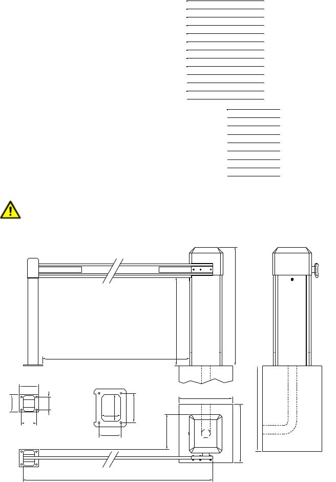
1.1.Measurements ES 25 – ES 40
|
160 |
140 |
110 |
130
Fixed support
Boom length minus 360mm
Drilling template barrier housing
Panel/Roadway |
247 |
273 |
|
179 |
|
203
820 1100
300 |
350 |
|||||||
|
|
|
|
|
|
|
|
|
|
|
|
|
|
|
|
|
|
|
|
|
|
|
|
|
|
|
|
500 |
|
|
|
800 |
320 |
550 |
Foundation |
|
|
|
|
|
500x550x800 |
2500/3000/4000
© 26.07.2006 ELKA-Torantriebe GmbH u. Co. Betriebs KG |
page 2 |
ES 25 – ES 80 (MO63) |
1.2.Installation ES 25 – ES 40
a)When you prepare the concrete foundation lay enough cable or a plastic duct for the cable you need. The foundation must be at least 800 mm deep with a horizontal surface 500 x 550 mm.
b)Using the template you can, either incorporate bolts in the foundation, or drill holes in the hardened concrete for heavy-duty fixings. The door side of the template must face towards the road on which the barrier will be closing.
c)As an alternative 2 "U"-profile clamping-irons are delivered with the barrier. This gives more flexibility in positioning the fastening points and allows the barrier to be aligned exactly as required.
Attention: The barrier is closed when shipped. The door faces towards the road.
d)Secure the barrier on the foundation.
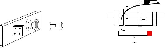
e)Connect the boom holder to the shaft. Tighten all screws, the top ones first with 35 Nm. The enclosed nuts and bolts are a predetermined breaking point and should only be replaced with the same.
(Bolt M 8 x 45 ISO 4762 12.9, Nut hexagonal M 8 ISO 4032 5-2)
Release bolt
Boom holder
|
|
|
|
|
|
|
|
|
|
|
|
|
|
|
|
|
|
|
|
|
|
|
|
|
|
|
|
|
|
|
|
|
|
|
|
|
|
|
|
|
|
|
|
|
|
|
|
|
|
|
|
|
|
|
|
|
|
|
|
|
|
|
|
|
|
|
|
|
|
|
|
|
|
|
|
|
|
|
|
|
|
|
|
|
|
|
|
|
|
|
|
|
Shaft |
|
|
|
Release lever |
|
|
|
|||||||
|
|
|
|
|
|
|
|
|
|
|
|
|
|
|
|
|
|
|
|
|
|
|
|
|
|
|
|
|
|
|
|
|
|
|
|
|
|
|
|
|
|
|
|
|
|
|
|
|
|
|
|
|
|
|
|
|
|
|
|
|
|
|
|
|
|
|
|
|
|
|
|
|
|
|
|
|
|
|
|
|
|
|
|
|
|
|
|
|
|
|
|
|
|
|
|
|
|
|
|
|
|
|
|
|
|
|
|
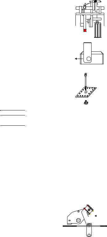
f)Emergency release during current failure etc. Pull the lever with the red end which is behind the access panel. The boom can then be raised manually. To engage the boom again pull the lever and pull the boom down, the release bolt will then lock at the appropriate position.
The controller is switched off until the boom is locked at the operating position.
g)Mount the boom before doing a test run. If necessary adjust the limit switches and the stoppers.
h)Start the programming mode (6.1 – Running time and automatic closure).
The logic board MO 63 is connected to the terminals (X1) in the barrier and to the microswitches in the head. All electrical connections should be carried out at the front of the terminals (X1). The barrier is ready for use when delivered. The running time and a ‘stay open’ time of 5 seconds are stored in an EEPROM.
You only need the programming mode if the time to stay open (when automatic closure is being used) is to be altered, the photo-cell test is activated or when a controller is replaced.
Switch off the mains supply before altering the operating mode dip switches!
© 26.07.2006 ELKA-Torantriebe GmbH u. Co. Betriebs KG |
page 3 |
ES 25 – ES 80 (MO63) |

2. Technical data ES 50ES 80
Operative range |
|
|
General data |
|
|
Application |
|
- Parking area, |
|
Mains supply |
230V / 50Hz |
for ... |
|
- Parking garage |
|
Max. current |
2.5A (max.) |
|
|
- Company entrance |
|
Duty cycle |
100% |
|
|
- Safety area |
|
Temperature range |
-20°C to +70°C |
Drive pulse |
|
- Push button, card reader, key switch, |
|
Controller |
|
MO 63 |
|||||
from ... |
|
remote control, desk top panel etc. |
|
Measurements (w/l/h) |
400x450x1100 mm |
|
|
- Handsfree data-capture |
|
Foundation (frost-proofed) |
600x650x800 mm |
|
|
- Induction loop |
|
Boom connector |
central |
Safety |
|
- Reversing on obstacle |
|
||
|
|
Housing |
aluminium |
||
|
|
- Best protecting against vandalism |
|
|
|
|
|
Mechanical parts |
steel, zinc coated |
||
|
|
- Ergonomic emergency release |
|
||
|
|
|
|
|
|
|
|
|
|
|
|
Typical Data |
ES 50 |
ES 60 |
ES 80 |
Drawn power |
0.26 kW |
0.26 kW |
0.26 kW |
Running time |
ca. 4.0 s |
ca. 5.5 s |
ca. 8.5 s |
Maximum boom length |
5000 mm |
6000 mm |
8000 mm |
Effective length |
5140 mm |
6140 mm |
8140 mm |
Fixed- / swinging support |
required |
required |
required |
Reversing on obstacle |
switchable |
switchable |
switchable |
Boom weight /{ |
10 / 9 kg |
16.5 / 11 kg |
23 / 14 kg |
Barrier weight |
110 kg |
115 kg |
118 kg |
The accident prevention regulations and the approved safety rules have to be observed. Moving parts inside the barrier can cause accidents.
Do not operate the barrier when housing is open.
2.1.Measurements ES 50 – ES 80
|
160 |
140 |
110 |
130
Fixed support
Length of boom
Drilling template
barrier housing 165 165
Panel/Roadway |
320 |
70 |
|
|
286 |
|
|
194 |
|
165 |
165 |
5000/6000/8000
145
843 1100
450 |
|
400 |
90 160
600 800
800
Foundation 600x650x800
650
© 26.07.2006 ELKA-Torantriebe GmbH u. Co. Betriebs KG |
page 4 |
ES 25 – ES 80 (MO63) |
2.2. Installation ES 50 – ES 80
a)When you prepare the concrete foundation lay enough cable or a plastic duct for the cable you need. The foundation must be at least 800 mm deep with a horizontal surface 600 x 650 mm.
b)Emergency release during current failure etc. Pull the lever with the red end which is behind the access panel. The boom can then be raised manually. To engage the boom again pull the lever and pull the boom down, the release bolt will then lock at the appropriate position. The controller is switched off until the boom is locked at the operating position.
c)Using the template you can, either incorporate bolts in the foundation, or drill holes in the hardened concrete for heavy-duty fixings. The door side of the template must face towards the road on which the barrier will be closing. Secure the barrier on its foundation. Ensure that the housing is vertical. The screws or bolts at the thickly marked points (drawing on page 4) also secure the foot of the spring assembly.
d)The left and right parts of the boom assembly aren’t identical. The greater distance between the edge and the hub must be towards the access panel. Secure the boom assembly on both ends of the shaft. The barrier is delivered in the open position, which means the assembly must be vertical. Secure the boom holder on the assembly. The two parts are then joined together.
e)Remove the adjusting nut from the spring assembly. If the boom is to be shortened reduce the number of springs. The following table shows approximate values, check that the balance is as described under f). The springs must be divided equally between the back and the front. One spring alone may not be used. The springs should be inspected regularly and be tightened or replaced, if necessary.
Release bolt |
|
|
assembly |
Release lever |
Spring |
|
|
|
Boom |
|
assembly |
Panel |
|
Counter nut
Adjusting nut
Length of boom [mm] ES 50 |
3000 |
Springs without folding skirt |
2 |
Spring with folding skirt |
2 |
3500 |
4000 |
4500 |
5000 |
2 |
2 |
3 |
3 |
3 |
3 |
4 |
5 |
Length of boom [mm] ES60/80 |
4000 |
4500 |
5000 |
|
5500 |
6000 |
|
6500 |
|
7000 |
|
7500 |
|
8000 |
|||||||
Springs without folding skirt |
4 |
4 |
5 |
|
6 |
|
8 |
|
8 |
|
|
10 |
|
|
11 |
|
12 |
||||
Spring with folding skirt |
5 |
6 |
7 |
|
8 |
|
10 |
|
12 |
|
14 |
|
|
16 |
|
18 |
|||||
The following values are only for the round boom |
|
|
|
|
|
|
|
|
|
|
|
|
|
|
|
|
|
|
|||
|
|
|
|
|
|
|
|
|
|
|
|
|
|
|
|
||||||
Length of boom [mm] ES50/60/80 |
3000 |
|
4000 |
|
4500 |
|
5000 |
|
5500 |
|
6000 |
|
7000 |
|
8000 |
||||||
Spring without folding skirt |
2 |
|
2 |
|
3 |
|
|
3 |
|
|
4 |
|
5 |
|
8 |
|
10 |
||||
Spring with folding skirt |
2 |
|
3 |
|
4 |
|
|
5 |
|
|
7 |
|
8/9 |
|
|
|
|
|
|||
f)When all electrical connections are completed, ensure that the spring assembly is not yet connected to the drive shaft. Close the barrier with the motor and then mount the boom. Pull the emergency release lever and push the boom into the vertical position. Screw the adjusting nut onto the connecting rod and tighten the springs. Pull the release lever again and push the boom down, if the spring tension is correct, it should move easily to about 45°. After that the boom has to be pushed down.
g)The connecting rod of the ES 50 to ES 80 consists of two parts which are screwed  together and form a predetermined breaking point in case of vertical force on the
boom. The boom is then disconnected from the shaft and is pulled to about 45° by the springs. If a break occurs here the nut and the bolts must be replaced with the original ELKA vandalism set. The nuts must be secured with thread lock.
The nuts may only be replaceed with those supplied by ELKA.
Shaft 

 Pre-determined breaking point
h)Start the programming mode (6.1 – Running time and automatic closure).
The logic board MO 63 is connected to the terminals (X1) in the barrier and to the microswitches in the head. All electrical connections should be carried out at the front of the terminals (X1). The barrier is ready for use when delivered. The running time and a ‘stay open’ time of 5 seconds are stored in an EEPROM.
You only require the programming mode if the time to stay open (when automatic closure is being used) is to be altered, the photo-cell test is activated or when a controller is replaced.
Switch off the mains supply before altering the operating mode dip switches!
© 26.07.2006 ELKA-Torantriebe GmbH u. Co. Betriebs KG |
page 5 |
ES 25 – ES 80 (MO63) |
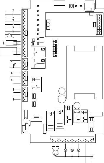
3. Controller MO 63
BT
BTA1
BTA2
BTZ1A
BTZ2
BTS1
BTS2
LS
BTZ1B
No boom
Barrier open Barrier closed common
SEA
SEZ
No boom
Stop
Photo-cell test 24V
24Vdc max. 500mA 12Vdc max. 500mA
|
1 |
|
2 |
|
3 |
|
4 |
|
5 |
|
6 |
V15 |
8 7 |
|
9 |
|
10 |
|
11 |
|
12 |
|
13 |
|
14 |
|
1 |
V6 |
2 |
|
3 |
|
1 |
V4 |
3 2 |
|
4 |
|
1 |
V12 |
3 2 |
|
4 |
LERN
BT |
Diag. Vp |
|
|
|
V9 |
||
BTA |
|
||
|
|
||
BTZ1 |
|
|
|
BTZ2 |
|
|
|
LS |
Receiver radio |
|
|
B1 remote control |
V14 |
||
BTS1 |
|||
|
|
||
BTS2 |
|
|
|
SEA |
ON 1098765 4 3 2 1 |
|
|
modeOperating |
|
||
|
VWA1 |
|
|
SEZ |
VWA2 |
|
|
VWZ |
|
ZLA
REV.
ZAHL
SZ
LSA
LSTST
RES.
MO63 |
Transformer |
|
|
|
|
|
|
|
10A |
Fuse |
1 |
2 |
3 |
4 |
5 |
6 |
7 |
|
|
|
|
V2 |
|
|
|
|
|
|
|
|
|
|
|
M
Motor Red light |
Green light |
|
||
Barrier closed |
Barrier open |
|
||
Amber or |
L1 |
N |
||
flashing light |
||||
230V |
50Hz |
|||
max. 120W |
||||
|
|
|||
3.1.Connections
BT |
Single push button |
(n.o. – V15.1 – X1/5t) |
|
With the serial switching BT the barrier can be opened and closed. Additional functions of BT |
|
|
depend on setting of the dip switches for automatic closure (S4) and the counter settings (S6). |
|
|
When the automatic closure is activated, or the counter is deactivated, then the barrier can be |
|
|
closed by BT – otherwise the barrier will be opened. When the automatic closure is blocked (e.g. |
|
|
by a stop signal), and the counter is activated, then BT can only open the barrier. Which means |
|
|
that closing by BT is not possible. |
|
BTA1 |
Push button ‘open’ 1 and 2 |
(n.o. – V15.2 – X1/6t and V15.3 – X1/6b) |
BTA2 |
When one of the contacts BTA1 or BTA2 is open and the other is closing, the barrier opens. |
|
|
When the barrier is open and BTA1 or BTA2 is being closed, then the barrier cannot be closed |
|
|
(constant open). |
|
BTZ1A |
Push button ‘close’ 1A and 1B |
(n.o. – V15.4 – X1/7t and V15.9 – X1/10b) |
|
When BTZ1A closes while BTZ1B is open, or BTZ1B closes while BTZ1A is open, the barrier |
|
|
closes. When the barrier is closed and at least one contact is closed, the barrier cannot be |
|
|
opened (constant closed). |
|
BTZ2 |
Push button ‘close’ 2 |
(n.o. – V15.5 – X1/7b) |
|
When the contact BTZ2 is opening, the order ‘close’ is given. |
|
© 26.07.2006 ELKA-Torantriebe GmbH u. Co. Betriebs KG page 6 |
ES 25 – ES 80 (MO63) |
|
 Loading...