

Elka TERRA 180, TERRA 320, TERRA 182, TERRA 322, TERRA 250 Installation And Operating Instructions Manual
...Page 1
Installation and operating instructions
Swing Gate Opener
TERRA 180/182 – TERRA 250/252 –
TERRA 320/322
Page 2

© 14.11.2005 ELKA-Torantriebe GmbH u. Co. Betriebs KG Page 2 TERRA 180/182 - 250/252 – 320/322
Safety relevant rules and regulations _____________________________________________________________3
General notes of safety _________________________________________________________________________4
1. Usage _____________________________________________________________________________________5
2. Technical Data ______________________________________________________________________________5
3. Installation dimensions (example) ______________________________________________________________6
4. Installation__________________________________________________________________________________7
4.1. Tools needed ______________________________________________________________________________8
4.2. Installation at the gate and gate post __________________________________________________________9
4. 2 . 1 . In s t a l l a t i o n a t t he g a t e p o s t____________________________________________________________________9
4.2.2. Emergency release_______________________________________________________________________10
4.2.3. Emergency releasing _____________________________________________________________________10
4.2.4. Engaging of emergency release ____________________________________________________________10
4.2.5. Installation at the gate ____________________________________________________________________11
4.3. Checking of the movement _________________________________________________________________12
4.4. Adjusting of the internal stops with the MO36__________________________________________________13
4.5. Removing of adjustment clip ________________________________________________________________18
4.6. Mounting of cover plate ____________________________________________________________________19
4.7. Re-adjusting of internal stops _______________________________________________________________20
5. Installation example_________________________________________________________________________21
6. Electrical installation ________________________________________________________________________21
7. Connection plan of the controller MO36 ________________________________________________________22
8. Programming MO36 _________________________________________________________________________25
8.1. Learning sequence ________________________________________________________________________25
8.1.1. Sequence P1: Learning of the running distance_______________________________________________26
8.1.2. Sequence P2: Adjusting of force and speed __________________________________________________27
8.1.3. Sequence P3: Time lag of the pedestrian wing (closing)________________________________________27
8.1.4. Sequence P4: Time lag of the main wing (opening) ____________________________________________27
8.1.5. Sequence P5: Learning and deleting of code for radio remote cont rol for BT, BTG and MULTI________28
8.1.6. Sequence P6: Automatic closure for complete opening ________________________________________28
8.1.7. Sequence P7: Automatic closure for pedestrian wing __________________________________________29
8.1.8. Sequence P8: Warning prior to opening and closing___________________________________________30
8.1.9. Sequence P9: Photo-cell function __________________________________________________________30
8.1.10. Sequence PA: Photo-cell testing __________________________________________________________31
8.1.11. Sequence PB: Lockage function for the photo-cells __________________________________________33
8.1.12. Sequence PC: Pressure relief of electromechanical bolt_______________________________________34
8.1.13. Sequence PD: Wind blast suppression _____________________________________________________34
8.1.14. Sequence PE: Multi-functional relay _______________________________________________________34
8.1.15. Sequence PF: Return to original settings ___________________________________________________35
9. Safety contact profiles for gate open (SLA) and close (SLZ)________________________________________35
10. Additional functions and additional modules___________________________________________________36
11. Power failure______________________________________________________________________________37
12. Fault diagnosis ____________________________________________________________________________37
13. Technical data MO36 _______________________________________________________________________38
Page 3
© 14.11.2005 ELKA-Torantriebe GmbH u. Co. Betriebs KG Page 3 TERRA 180/182 - 250/252 – 320/322
Safety relevant rules and regulations
The swing gate controller MO36 has been developed and manufactured according to EN12453 Industrial
commercial and garage doors and gates – Safety in use of power operated doors - Requirements. All notes
in this instruction have to be obeyed by the user. All work and repairs on electrical appliances must be
carried out by qualified persons only. They have to be knowledgeable about the relevant regulations. They
have to be able to recognise possible safety hazards and take necessary safety actions. The operational
safety of the controller MO36 is only guaranteed during usage as intended.
During installation, initial operation phase, maintenance and testing of the controller the individually relevant
regulations for safety and accident prevention have to be obeyed.
These are the following directives and standards: (list is not necessarily complete):
- EN12445: Industrial commercial and garage doors and gates – Safety in use of power operated
doors – Test methods
- EN12453: Industrial commercial and garage doors and gates – Safety in use of power operated
doors - Requirements
- EN60335-1: Household and similar electrical appliances – Safety –Part 1: General requirements
Power supply: 230Vac, 50Hz, single phase.
Connection: By fixed wiring and main switch (on site) or flexible wiring with cable stress relief device
according European standards.
Symbols:
WARNING! Danger of harm to people and objects
INFORMATION! Important information for installation and operation
REMARK! Remarks for the installation
Page 4

© 14.11.2005 ELKA-Torantriebe GmbH u. Co. Betriebs KG Page 4 TERRA 180/182 - 250/252 – 320/322
General notes of safety
These operating instructions must be available on site at all times. It should be read thoroughly by all
persons who use, or service the appliances. Improper usage or servicing or ignoring the operating
instructions can be a source of danger for persons, or result in material damage. If the meaning of any part
of these instructions isn’t clear, then please contact ELKA Torantriebe GmbH u. Co. Betriebs KG before you
use the appliance.
This applies to all setup procedures, fault finding, disposal of material, care and servicing of the appliance.
The accident prevention regulations and applicable technical regulations (e.g. safety or electrical) and
environment protection regulations of the country in which the appliance is used also apply.
All repairs on the appliances must be carried out by qualified persons. ELKA Torantriebe GmbH u. Co.
Betriebs KG accepts no liability for damage which is caused by using the appliance for purposes other than
those for which it is built.
ELKA Torantriebe GmbH u. Co. Betriebs KG cannot recognise every possible source of danger in advance.
If the appliance is used other than in the recommended manner, the user must ascertain that no danger for
himself or others will result from this use. He should also ascertain that the planned use will have no
detrimental effect on the appliance itself. The appliance should only be used when all safety equipment is
available and in working order. All faults which could be a source of danger to the user or to third persons
must be eliminated immediately. All warning and safety notices on the appliances must be kept legible.
All electrical periphery equipment which is connected to the appliance must have a CE Mark, which ensures
that it conforms to the relevant EEC regulations. Neither mechanical nor electrical alterations to the
appliance, without explicit agreement of the manufacturer, are allowed. All alterations or extensions to the
appliance must be carried out with parts which ELKA Torantriebe GmbH u. Co. Betriebs KG have defined as
suitable for such alterations, and be carried out by qualified personnel.
Any contravention of these conditions revokes the manufacturer’s guarantee and also the CE Mark and the
user is alone responsible for the consequences.
Our service department is available to answer all queries about these conditions and, of course, about our
appliances.
We reserve the right to make technical improvements without prior notice.
The operation of the system within CEN countries must also be conformant with the European safety-relevant
directives and standards.
Page 5

© 14.11.2005 ELKA-Torantriebe GmbH u. Co. Betriebs KG Page 5 TERRA 180/182 - 250/252 – 320/322
1. Usage
The TERRA is suitable for one or two-winged gates moving horizontally and having low
wind resistance. For max. width and weight of gate wing see table below.
When usage is different from the above samples, please contact your
supplier.
2. Technical Data
TERRA 180/182
one winged gate /
two winged gate
TERRA 250/252
one winged gate /
two winged gate
TERRA 320/322
one winged gate /
two winged gate
Maximum width of wing *
1.800mm / wing 2.500mm / wing 3.200mm / wing
Maximum weight of wing *
500kg 500kg 500kg
Electromagnetic bolt
No No
Yes, required for
wings from 2.500mm
Emergency release on current failure
Yes Yes Yes
Opening angle max.
180° 180° 180°
Running time (opening angle 90°) **
(each wing)
approx. 12s approx. 12s approx. 16s
Limit stoppers at opened and closed
positions
***
Position CLOSE recommended (required for wings from2.500mm)
Position OPEN not required (required for wings from2.500mm)
Power supply
230V, 50Hz 230V, 50Hz 230V, 50Hz
Operating voltage
24 V = 24 V = 24 V =
Duty cycle
50% 50% 50%
Blocking when open / closed
Yes Yes Yes
Soft-Start and Soft-Stop
Yes, with ramp
function
Yes, with ramp
function
Yes, with ramp
function
Pedestrian opening
Yes Yes Yes
Controller, separately (WxHxL)
MO36
(
175x260x100mm
)
MO36
(
175x260x100mm)
MO36
(
175x260x100mm
)
Traffic light
Module (optional) Module (optional) Module (optional)
Safety contact profile
Separately for OPEN
and CLOSE
Separately for OPEN
and CLOSE
Separately for OPEN
and CLOSE
Weight
approx. 47kg / 92kg approx. 48kg / 93kg approx. 49kg / 94kg
Degree of protection
IP 44 IP 44 IP 44
Temperature range
-20°C up to +70°C -20°C up to +70°C -20°C up to +70°C
Maintenance
The maintenance intervals must be decided individually as they are
dependent on the frequency of use. We recommend maintenance at least
once every 12 months.
* gates with low wind resistance Table 1
** depending on the installation dimensions
*** end stops at the main wing are not necessarily required for a gate width up to
2,500mm, but are recommended for position CLOSED.
Page 6
© 14.11.2005 ELKA-Torantriebe GmbH u. Co. Betriebs KG Page 6 TERRA 180/182 - 250/252 – 320/322
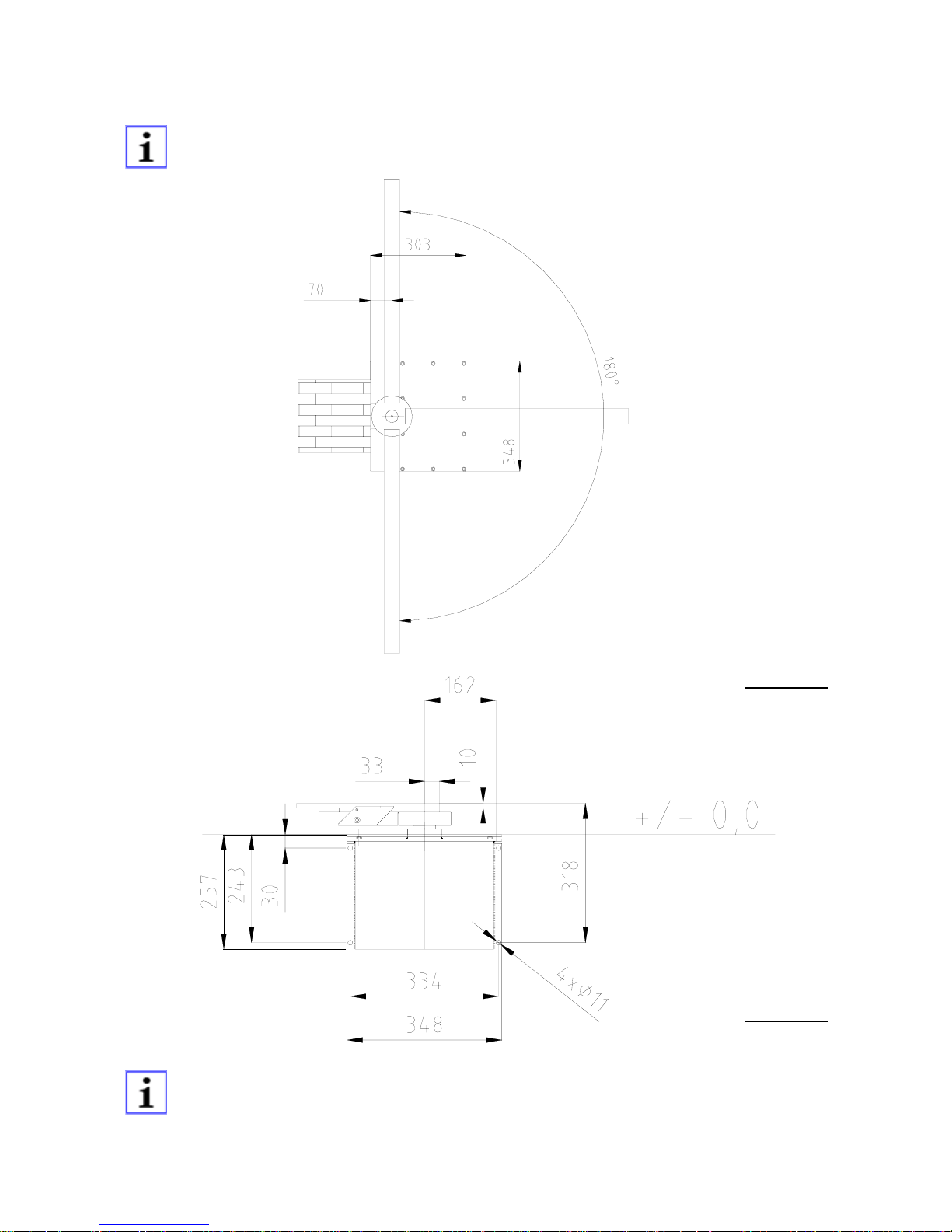
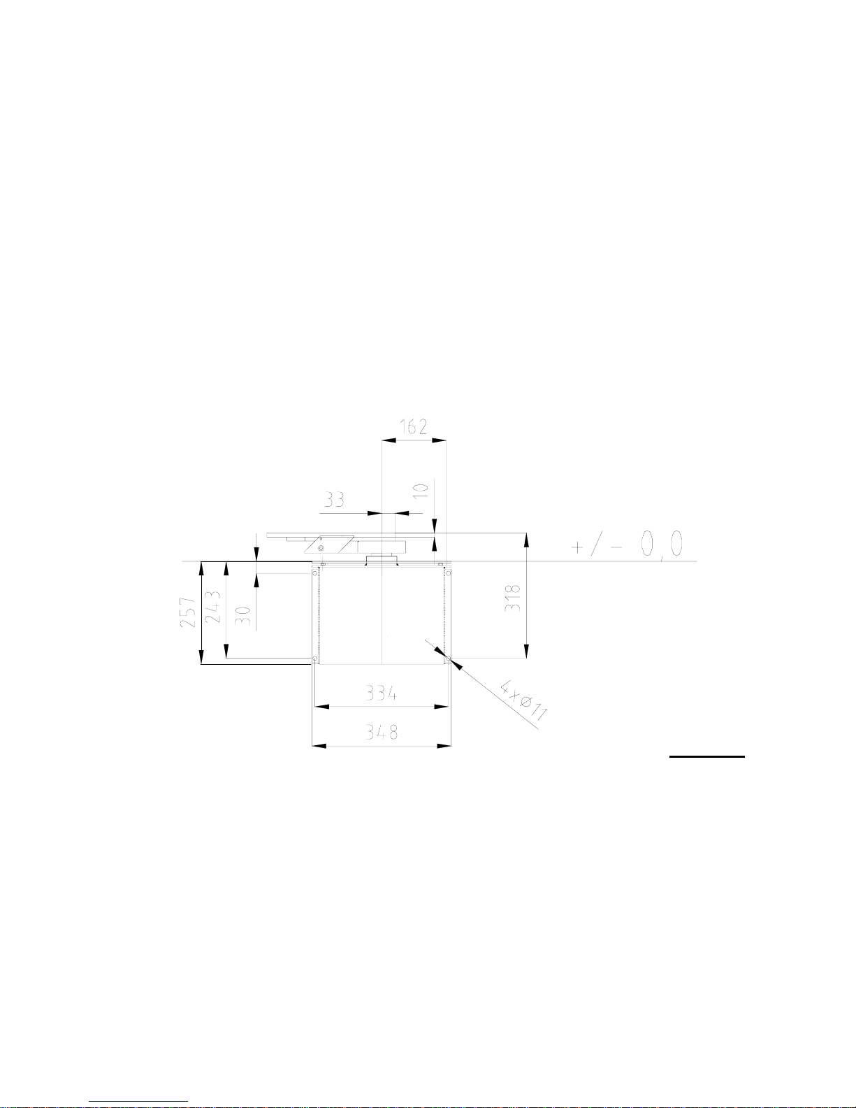
3. Installation dimensions (example)
When installing next to the gate either with set 1 or set 2, please use the
measurements in the respective installation manual.
Drawing 1
Drawing 2
Please make sure, that the gate wings can be moved easily and that the axis of
rotation is in a completely vertical position.
End stops for gate OPEN and CLOSED are required for wings of 2,500mm and
larger.
Page 7
© 14.11.2005 ELKA-Torantriebe GmbH u. Co. Betriebs KG Page 7 TERRA 180/182 - 250/252 – 320/322
4. Installation
Important:
Warning! The controller needs to be disconnected while welding is
performed on the gate.
Internal stops have to be adjusted according to paragraph 4.4, even though when
external stops exist (see also paragraph 4.2 – emergency release).
Do not remove the adjustment clip before the adjustment of the internal
stops is completed (see paragraph 4.5 – removing of the adjustment clip).
Warning! Please do not leave the emergency release key in the key lock.
Please do not remove the protective foil and the protective tape before
installation has been completed (see paragraph 4.2).
In case external stops exist and are in use, adjust the wing/s in such a way
that they touch the external stops with the least possible tension.
The motor-connection cable (cross section 5x1.5mm²) should be laid through
a suitable conduit (shortest distance) to the next joint box. This mechanical
protection (conduit) has to be assured all the way to the joint box. Use a
suitable cable from the joint box onward.
Grommet
Drawing 3
Page 8

© 14.11.2005 ELKA-Torantriebe GmbH u. Co. Betriebs KG Page 8 TERRA 180/182 - 250/252 – 320/322
Mechanical parts
1 2 3 4
5 6 7 8
Drawing 4
1 Housing
2 Cover plate
3 Support profile
4 Mounting plate
5 Gate support
6 Welding profile
7 Emergency release lever
8 Adjustment clip
4.1. Tools needed
The following tools are needed (on site) for the installation:
1 Torque wrench 30 – 50Nm
1 Allen key 6mm matching the above
1 Extension piece 100mm for torque wrench
1 Allen key 4mm (ball-ended)
Installation bolts on site.
Page 9
© 14.11.2005 ELKA-Torantriebe GmbH u. Co. Betriebs KG Page 9 TERRA 180/182 - 250/252 – 320/322
4.2. Installation at the gate and gate post
4.2.1. Installation at the gate post
Depending on the type of gate post, installation is possible either completely on site,
partially prepared on site, or completely prepared at the installer`s workshop.
Important: The bottom of the underfloor opener has to be set on a concrete foundation
(on site). The 4 mounting straps are only an installation aid. They are not made for
absorption of the force developed during movement of the gate. The underfloor housing
has to be laid in concrete at least half way up the sides of the housing.
Note: Do not remove the protective foil and the protective tape which covers the gap
between the cover plate and the underfloor housing. They protect the seal area against
building material during the installation
a) Wall or wall posts:
The underfloor housing of the TERRA gate opener has 4 mounting straps on its rear
side to screw onto the post. Please see the drawing with the height measurements
below for the positioning of the screws to set the rawl plugs in the walling.
Drawing 5
b) Metal posts:
At gate posts made of steel or aluminium you may pre-mount fastening straps,
where the underfloor housing can then be fixed with screws.
c) Metal posts:
You pre-mount the gate opener onto the gate at your workshop completely and
install this unit on site.
Page 10
© 14.11.2005 ELKA-Torantriebe GmbH u. Co. Betriebs KG Page 10 TERRA 180/182 - 250/252 – 320/322
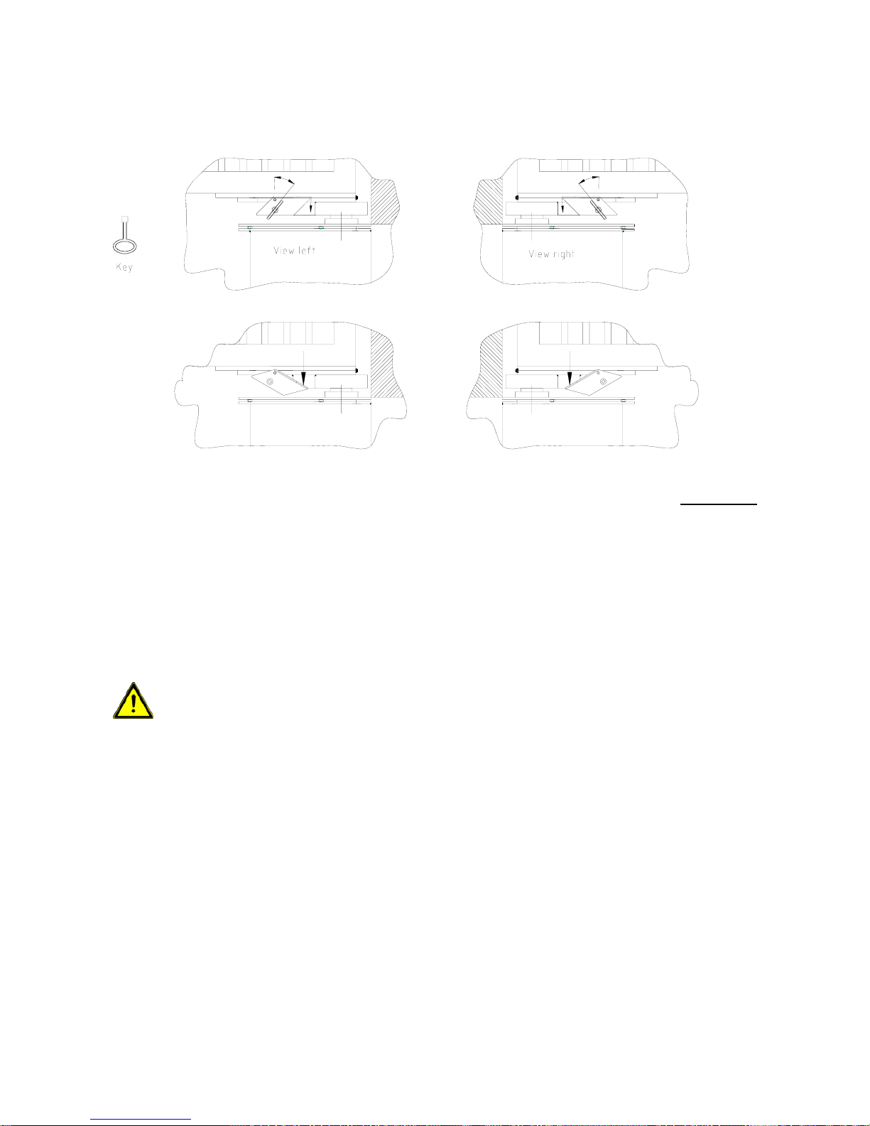
4.2.2. Emergency release
Damit die Notentriegelung einwandfrei arbeitet, muss der Torflügel mechanisch
spannungsarm in der Position AUF und ZU stehen.
Drawing 6
4.2.3. Emergency releasing
Open the cover of the cylinder lock below the gate support (see drawing 6). Insert the key
and turn it 90° anti-clockwise. Pull the emergency release lever downwards. The gate
opener is now released and the gate can be moved freely.
ATTENTION! The internal stops are not working now. The gate now can be
moved further than the regular end positions.
4.2.4. Engaging of emergency release
Push the emergency release lever up. Turn the key 90° clockwise. Remove the key and
close the cover of the cylinder lock. Move the gate until the emergency release engages.
Page 11
© 14.11.2005 ELKA-Torantriebe GmbH u. Co. Betriebs KG Page 11 TERRA 180/182 - 250/252 – 320/322
60
320
33
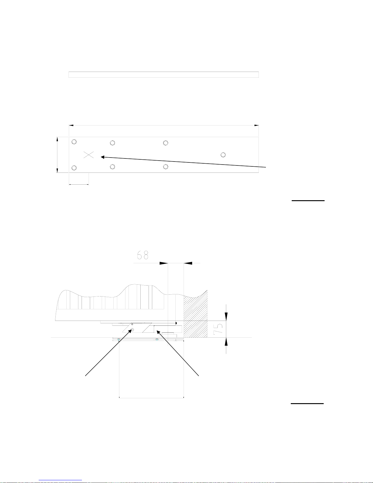
4.2.5. Installation at the gate
Use the included welding profile. There are 4 tapholes at one end of the welding profile.
The pivot point of the gate is located between these tapholes.
Pivot point
Drawing 7
We recommend the use of the upper hinge-set.
Emergency release Driver plate
Drawing 8
Page 12
© 14.11.2005 ELKA-Torantriebe GmbH u. Co. Betriebs KG Page 12 TERRA 180/182 - 250/252 – 320/322
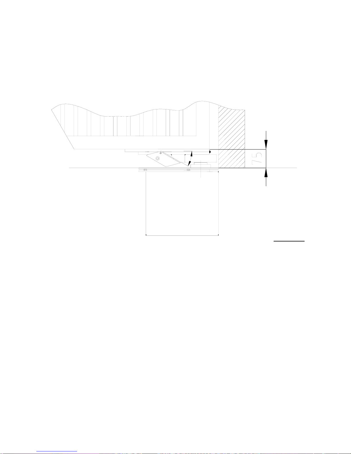
The welding profile can be used as drilling template.
Connect the gate support with the provided screws to the gate wing. The emergency
release is located in the gate support. Use the enclosed key to release the emergency
release lock and push the lever down. The nosing moves into the gate support. There is a
50mm ∅ drilling hole in the bottom of the gate support. Now place the gate into the upper
hinge. Place the gate with the gate support onto the gearbox shaft, which protrudes from
the underfloor opener. Push the lever up and lock the emergency release with the key (see
drawing 7).
Drawing 9
Move the gate until the nosing of the emergency release engages into the driver plate by
itself. Now the gate opener and the gate wing are connected again.
4.3. Checking of the movement
Release the gate opener manually again. Check, if the gate can be moved easily by hand
between OPEN and CLOSED. Engage the release in any chosen gate position. When the
gate is moved again, the nosing engages automatically (original installation position). Now
the gate opener and the gate wing are connected again.
Page 13

© 14.11.2005 ELKA-Torantriebe GmbH u. Co. Betriebs KG Page 13 TERRA 180/182 - 250/252 – 320/322
4.4. Adjusting of the internal stops with the MO36
4.4.1. Information for the adjusting
Note: For gates with two wings, the pedestrian wing opens first.
Max. permitted force setting: The original setting is force level 30. Change the force
settings only, when the original settings are not sufficient during learning. The max.
permitted force setting depends on the gate opener size:
Gate opener max. force setting
TERRA 180/182 35
TERRA 250/252 55
TERRA 320/322 75
Table 2
Nosing support
Ring stoppers
Interneral stop
Internal nosing
Adjustment clip
Gear shaft
Drawing 10
Page 14

© 14.11.2005 ELKA-Torantriebe GmbH u. Co. Betriebs KG Page 14 TERRA 180/182 - 250/252 – 320/322
4.4.2. Gates with one wing
a. Remove the protective foil and protective tapes from the gate opener.
b. Remove the cover plate from the underfloor housing.
c. Make sure that the adjustment clip is in its position.
d. Check that the emergency release is engaged. The gate wing should not be in either
end position.
e. Now connect the gate opener to the 5-pin connection FAHR on the controller MO36.
Please pay attention to the correct wiring.
Contacts at the motor
(Cable cross section)
Mark Contacts on the MO36
green (0.15mm²) 1 GND
white (0.15mm²) 2 IMP
brown (0.15mm²) 3 I+
blue (1.5mm²) 4 Mbrown (1.5mm²) 5 M+
Table 3
f. Connect to the mains.
Attention: During the next steps the gate wing will be moved electrically.
Make sure the range of movement is free from obstacles.
Attention: During learning the safety devices can react differently from the
normal operation.
g. Press the button LERN on the controller for approx. 2 seconds. The display shows P1.
h. Press the button LERN again. The display now shows 1F.
i. Now select the number of gate wings. Confirm the displayed 1F (for one wing) with the
button LERN.
j. The display shows HA (manual operation).
k. Now you can move the gate wing into the end positions in slow mode (dead man´s
function). The gate wing moves into direction OPEN only as long as button BT is
pressed. When button BT is pushed again, the wing moves into direction CLOSED.
l. Now move the gate wing with button BT into the end postitions OPEN and CLOSED.
The internal end stops are now adjusted but not fixed.
m. Move the gate wing with button BT into position „half OPEN“.
Attention: Do not give any further commands to the controller now.
j. Remove the plug from the 5-pin connection FAHR.
k. Mark the position of the pinion and the gear shaft to each other for the following
installation steps (see drawing 9).
l. Remove the marked pinion off the gear shaft.
m. Now you can reach the 8 countersunk-screws (by 6mm allen key).
These screws must be tightened by a torque wrench
with 45 Nm.
Use the torque wrench to fix the internal stops!
Page 15

© 14.11.2005 ELKA-Torantriebe GmbH u. Co. Betriebs KG Page 15 TERRA 180/182 - 250/252 – 320/322
n. Replace the pinion and make sure that the marks on pinion and gear shaft correspond.
o. Replace the plug to the 5-pin connection FAHR.
Attention: The gate moves automatically during the next installation step.
p. Next the controller learns the running distance of the gate wing. Push the button LERN.
The controller moves the gate wing into direction OPEN until the end stop and then into
direction CLOSED until the end stop (display P2).
The gate is now in position CLOSED. Should the gate now be in position OPEN, the
wires 4 and 5 of the motor connection cable at the 5-pin connection have to be
switched. Then repeat step p) by pressing button BTG once (display P1) and
pressing button LERN three times (display 1F, HA and AU).
q. Push button BT until PP is displayed. Confirm with button LERN.
In case it is necessary to change the position of the internal stops (changing
of the gate, exchanging of the motor etc.), see paragraph 4.7. – Re-adjusting
of internal stops.
r. Continue with paragraph 4.5.
For additional options for adjusting of the controller see paragraph 8.1.
Page 16

© 14.11.2005 ELKA-Torantriebe GmbH u. Co. Betriebs KG Page 16 TERRA 180/182 - 250/252 – 320/322
4.4.3. Gates with two wings
a. Remove the protective foil and protective tapes from the gate opener.
b. Remove the cover plate from the underfloor housing.
c. Make sure that the adjustment clip is in its position.
d. Check that the emergency release is engaged. The gate wings should not be in either
end position.
e. Now connect the gate openers to the 5-pin connections FAHR and GEH on the
controller MO36. Please pay attention to the correct wiring.
Contacts at the motor
(Cable cross section)
Mark Contacts on the MO36
green (0,15mm²) 1 GND
white (0,15mm²) 2 IMP
brown (0,15mm²) 3 I+
blue(1,5mm²) 4 Mbrown (1,5mm²) 5 M+
Tabelle 4
f. Connect to the mains.
Attention: During the next steps the gate wing will be moved electrically.
Make sure the range of movement is free from obstacles.
Attention: During learning the safety devices can react differently from the
normal operation.
g. Press the button LERN on the controller for approx. 2 seconds. The display shows P1.
h. Press the button LERN again. The display now shows 1F.
i. Now select the number of gate wings. Push button BT until it displays 2F. Confirm the
displayed 2F (for two wings) with the button LERN.
j. The display shows HA (manual operation).
k. Now you can move each gate wing separately into the end positions in slow mode
(dead man´s function). The main wing moves into direction OPEN only as long as
button BT is pressed. When button BT is pushed again, the wing moves into direction
CLOSED. The pedestrian wing moves into direction OPEN only as long as button BTG
is pressed. When button BTG is pushed again, the wing moves into direction CLOSED.
l. Now move the main wing with button BT into the end postitions OPEN and CLOSED.
Now move the pedestrian wing with button BTG into the end positions OPEN and
CLOSED. The internal end stops are now adjusted but not fixed.
m. Move the gate wings with button BT and BTG into position „half OPEN“.
Attention: Do not give any further commands to the controller now.
n. Remove the plug from the 5-pin connection FAHR.
o. Mark the position of the pinion and the gear shaft to each other for the following
installation steps (see drawing 9).
p. Remove the marked pinion off the gear shaft.
q. Now you can reach the 8 countersunk-screws (by 6mm allen key).
These screws must be tightened by a torque wrench with
45 Nm.
Use the torque wrench to fix the internal stops!
Page 17

© 14.11.2005 ELKA-Torantriebe GmbH u. Co. Betriebs KG Page 17 TERRA 180/182 - 250/252 – 320/322
r. Replace the pinion and make sure that the marks on pinion and gear shaft correspond.
s. Replace the plug to the 5-pin connections.
Attention: The gate moves automatically during the next installation step.
t. Next the controller learns the running distance of the gate wing. Push the button LERN.
The controller moves the gate wing into direction OPEN until the end stop and then into
direction CLOSED until the end stop (display P2).
The gate is now in position CLOSED. Should the gate now be in position OPEN, the
wires 4 and 5 of the motor connection cable at the 5-pin connection have to be
switched. Then repeat step p) by pressing button BTG once (display P1) and
pressing button LERN three times (display 2F, HA and AU).
u. Push button BT until PP is displayed. Confirm with button LERN.
In case it is necessary to change the position of the internal stops (changing
of the gate, exchanging of the motor etc.), see paragraph 4.7. – Re-adjusting
of internal stops.
v. Continue with paragraph 4.5.
For additional options for adjusting of the controller see paragraph 8.1.
Page 18

© 14.11.2005 ELKA-Torantriebe GmbH u. Co. Betriebs KG Page 18 TERRA 180/182 - 250/252 – 320/322
4.5. Removing of adjustment clip
To adjust the internal end stops it is absolutely necessary that the nosings are not active.
Deactivate them with the adjustment clip. To activate the nosings for regular operation,
remove the adjustment clip. Pull the clip out of the gate opener using the adhesive strap.
Marks
(see 4.8f)
Adjustment clip
Gear shaft
Pinion
Drawing 11
For perfect operation of the gate system it is now necessary to activate the pressure
relief for the electromagnetic bolt.
a. Press the button LERN on the controller for approx. 2 seconds (display shows P1)
b. Push button BT a few times until the display shows PC.
c. Push button LERN (display shows S1)
d. Push button BT (display shows S2). Confirm with button LERN.
e. Push button BT a few times until the diplay shows PP.
f. Push button LERN.
g. The selection is now active.
Save the adjustment clip with the manual. Do not dispose of the adjustment
clip!
Page 19

© 14.11.2005 ELKA-Torantriebe GmbH u. Co. Betriebs KG Page 19 TERRA 180/182 - 250/252 – 320/322
4.6. Mounting of cover plate
ATTENTION! Make sure the seal area at coverplate and underfloor housing is free
of dirt.
ATTENTION! Make sure the seal is free of dirt and damages.
Underfloor housing
Seal
Drawing 12
6 x Screw with seal
Drawing 13: Cover plate
Replace the cover plate onto the underfloor housing.
ATTENTION! Tighten the screws only 1 turn unto the point when the thread
barely holds the screws. Do not fasten the screws completely yet.
Piece by piece insert all fastening screws, starting at the corners. Please make sure not to
damage the seal. Please make sure that the 6 fastening screws at the gear shaft are
equipped with their seals. The seal between cover plate and housing is to be
inserted according to the drawing.
Now the fastening screws can be tightend crosswise -step by step- completely.
Page 20

© 14.11.2005 ELKA-Torantriebe GmbH u. Co. Betriebs KG Page 20 TERRA 180/182 - 250/252 – 320/322
4.7. Re-adjusting of internal stops
In case it is necessary to change the position of the internal stops (changing
of the gate, exchanging of the motor etc.), follow these steps:
a. Check that the emergency release is engaged. The gate wings should not be in
either end position.
b. Press the button LERN on the controller for approx. 2 seconds. The display shows
P1.
c. Confirm with the button LERN. The display shows HA (manual operation).
d. Move the gate wings with button BT and BTG into position „half OPEN“.
Attention: Do not give any further commands to the controller now.
e. Remove the plug from the 5-pin connection FAHR or GEH.
f. Insert the adjustment clip from above into the gate opener. The level part of the
adjustment clip points away from the gear shaft.
g. Make sure the marks on the pinions and gear shaft correspond (see drawing 9).
h. Remove the marked pinion off the gear shaft.
i. Losen the 8 countersunk-screws (6mm allen screw, M10x25) only far enough until
they can be turned freely. Do not remove the screws.
j. Turn the nosing stoppers, one clockwise and the other one counterclockwise until
they touch the internal stop (see drawing 10).
k. Replace the pinion and make sure that the marks on pinion and gear shaft
correspond.
l. Replace the plug to the 5-pin connections.
m. Continue with paragraph 4.4.2.g (gates with on wing) or 4.4.3.g (gates with two
wings).
Nosing stoppers
Internal stop
Countersunk-screws
M10x25
Torque 45Nm
Drawing 14: Turning of the nosing stoppers (see 4.7.h.)
Page 21

© 14.11.2005 ELKA-Torantriebe GmbH u. Co. Betriebs KG Page 21 TERRA 180/182 - 250/252 – 320/322
5. Installation example
Drawing 15
6. Electrical installation
For swing gate openers with radio remote control the controller MO36 should be installed
as close as possible to the gate. The control box should be mounted with the entrance for
wiring at the bottom.
The lead from controller to motor should have at least the cross section stated below. A
smaller gauge will have adverse effect on the motor performance.
Cross section: 5 x 1.5 mm² up to max. 20 m
Cross section: 5 x 2.5 mm² up to max. 40 m
Power supply: 230Vac, 50Hz, single phase
Connection: By fixed wiring and main switch (on site) or flexible wiring with cable
stress relief device according to European standards.
For the connection motor – controller please use a suitable cable (underground
cable), possibly with a mechanical protection (conduit). The motor cable (enclosed in
shipment) is only suited for the shortest way to the connection box, possibly with a
mechanical protection. To avoid mistakes please use marked (colour) or numbered
leads within the 5-leads cable.
Page 22

© 14.11.2005 ELKA-Torantriebe GmbH u. Co. Betriebs KG Page 22 TERRA 180/182 - 250/252 – 320/322
main wing (or 1-winged
gates) with 24Vdc motor with
pulser
LS-Test
12Vdc
24Vdc
GND
Ampelmodul
AMO34A
230Vac
BZ
BA
BT
BTG
STOPP
BT
BTG
AMPEL
WARN 230Vac/max. 60W
green traffic light 230Vac
MULTI 230Vac/max. 60W
timer module ASU2
radio remote
control receiver
LERN
magnetic lock 24Vdc/max 1A
pedestrian wing with 24Vdc
motor with pulser
N
PE
L1
LSI
LSA
SLA
SLZ
BT
BTGBABZ__BS
__
VP
LSI
LSA
8,2kO
8,2kO
SLA
SLZ
electromagnetic bolt 24Vdc/max 1A
red traffic light 230Vac
7. Connection plan of the controller MO36
Each safety contact strip terminal which is not used has to be linked to an 8.2 kΩ
resistor.
Each photo-cell and stop terminal which is not used has to be linked to a jumper.
Drawing 16
Page 23

© 14.11.2005 ELKA-Torantriebe GmbH u. Co. Betriebs KG Page 23 TERRA 180/182 - 250/252 – 320/322
7.1. Connections
7.1.1. Input terminals
Input Description Connection Function
BT n.o. contact 1 pin Push button (serial switching)
BTG n.o. contact 1 pin Push button for pedestrian opening
BA n.o. contact 1 pin Push button OPEN
BZ n.o. contact 1 pin Push button CLOSE
Ground - 1 pin Mutual ground BT, BTG, BA and BZ
LSA
LSI
Each max. 6 photo-cells with n.c.
contact and terminating resistor
1kΩ
2 pin Photo-cells for installation outside (LSA)
and inside (LSI) - (according to EN954-1
category 2)
Ground - 1 pin Mutual ground LSA and LSI
SLA
SLZ
Safety contact profile:
a) resistor detection
b) n.c. contact with 8.2kΩ
resistor (serial or parallel with
n.o. contact with 8.2 kΩ)
2 pin Integrated detectors with testing function
(according to EN954-1 category 2) for
safety contact profile for gate OPEN (SLA)
and CLOSE (SLZ)
Ground - 1 pin Mutual ground SLA and SLZ
IMPg
pulser See motor Pulser for pedestrian wing
IMPf
pulser See motor Pulser for main wing
SU Plug socket Connection for timer module ASU2
Funk Plug socket
for receiver
EKX1OF or
receiver
with
decoder
Integrated receiver for BT, BTG and MULTI
Mains
(L1, N,
PE)
- 3 pin Power supply 230Vac – L1, N and PE
Table 5
7.1.2. Buttons on the controller
Mark Function
BT Same function as external button BT
BTG Same function as external button BTG
LERN Starting the learning mode
Table 6
7.1.3. LEDs on the controller
Mark Colour Function Desired value
Vp Yellow Lights when connected to main power ON
SLA Red Lights when safety contact profile SLA active OFF
SLZ Red Lights when safety contact profile SLZ active OFF
BT Green Lights when the contact is closed OFF,
when pushing button = ON
BTG Green Lights when the contact is closed OFF,
when pushing button = ON
BA Green Lights when the contact is closed OFF,
when pushing button = ON
BZ Green Lights when the contact is closed OFF,
when pushing button = ON
BS Green Lights when the contact is closed ON
LSA Green Lights when LSA is interrupted OFF
LSI Green Lights when LSI is interrupted OFF
Display Red 2 x 7-segment-display OFF
Table 7
Page 24

© 14.11.2005 ELKA-Torantriebe GmbH u. Co. Betriebs KG Page 24 TERRA 180/182 - 250/252 – 320/322
7.1.4. Output terminals
Output Connection Corresponds to:
Motor pedestrian
wing and IMP
g
5 pin Connection for 24Vdc motor and pulser for the pedestrian
wing
Motor main wing
and IMP
f
5 pin Connection for 24Vdc Motor and pulser for the main wing or
for one-winged gates
SCHLOSS 3 pin Connection for electromagnetic bolt or magnetic lock with
24Vdc (max. 1A)
WARN 2 pin Potential-free contact for warning light 230Vac / max. 60W
MULTI 2 pin Potential-free contact for multi-functional relays (230Vac /
max. 60W)
Uext 3 pin 24Vdc and 12Vdc, mutual ground terminal, stabilised direct
voltage, together max. 300mA, ground terminal is connected
with controller ground
LS-TEST 1 pin 24Vdc for photo-cell transmitter
PE 1 pin Earth
AMPEL 2 pin Socket for traffic light module AMO34A red / green
Table 8
Page 25

© 14.11.2005 ELKA-Torantriebe GmbH u. Co. Betriebs KG Page 25 TERRA 180/182 - 250/252 – 320/322
8. Programming MO36
For programming and to set operating parameters, use the two-digit 7-segment display
and the buttons BT, BTG and LERN.
At least the following sequences have to be learned as basic
configuration:
P1 - Learning of running distance
P2 - Selecting of force and speed
PC - Pressure relief of electromagnetic bolt (see notes!)
8.1. Learning sequence
During normal operation the display is off. The learning sequence is activated by pushing
the button LERN for approx. 2s. The display shows P1. The sequence 1 is pre-set. With
the button BT you can move on to the next sequence P2, P3 etc.
With the button BTG you can move back to the last sequence. When the required
sequence is displayed it has to be activated with the button LERN.
Sequence Function
P1
- Selection one wing / two wings
- Adjusting of end stops
- Learning of safety contact profiles and photo-cells connected
- Learning of running distance
P2
Adjusting of force and speed
P3
Adjusting of time lag of the pedestrian wing during closing
P4
Adjusting of time lag of main wing during opening
P5
Learning and deleting of radio remote control codes for BT, BTG and MULTI
P6
Automatic closure for complete opening (for both wings)
- activating / deactivating
- change stay-open time
P7
Automatic closure for pedestrian wing
- activating / deactivating
- change stay-open time
P8
Selecting of warning prior to opening and closing
P9
Selecting of photo-cell function
PA
Activating / deactivating photo-cell testing
PB
Activating / deactivating lockage function for photo-cells
PC
Selecting pressure relief of electromagnetic bolt
PD
Selecting wind blast suppression
PE
Selecting mode of multi-functional relay
PF
Return to original settings
PP
Saving of data and returning to regular mode
Table 9
Page 26

© 14.11.2005 ELKA-Torantriebe GmbH u. Co. Betriebs KG Page 26 TERRA 180/182 - 250/252 – 320/322
8.1.1. Sequence P1: Learning of the running distance
When sequence P1 has been activated, it has to be selected first between gates with one
(1F) or with two (2F) wings using button BT. Then confirm the selection with button LERN.
Display Effect / Function
1F
To operate gates with one wing
2F
To operate gates with two wings
Table 10
Then HA is displayed. The gate wings now can be operated by dead man’s motion using
buttons BT or BTG to adjust the internal mechanical end stoppers (when using openers
like TERRA or ZENIT). BT is used for the main wing and BTG for the pedestrian wing. The
first direction is always OPEN.
Attention! During learning the safety devices may act different from the
regular operation. Please ensure that no people are in the danger area during
learning.
After adjusting the end stoppers, push the button LERN to continue: The controller tests
the safety contact strips and the photo-cells. It learns the type of the safety contact strips
(8.2 kΩ) and the number of connected photo-cells. Only when this photo-cell testing was
successful, additional photo-cell tests can be carried out during future operation.
Gates with one wing:
During learning of the running distance the wing opens first and then closes.
Gates with two wings:
During learning of the running distance the pedestrian wing opens, the main wing opens,
the main wing closes and pedestrian wing closes.
In both cases the wings move until they hit the stoppers at the closed position. During the
learning of the running distance the pressure relief of the electromechanical bolt is not in
function. The electromechanical bolt is being activated during each wing movement.
After the learning of the running distance, returning to the main sequence follows
automatically.
Remark: After adjustment of the end stoppers, the wings should not be in either
end position but at least 50cm before. The first movement is into direction open.
Page 27

© 14.11.2005 ELKA-Torantriebe GmbH u. Co. Betriebs KG Page 27 TERRA 180/182 - 250/252 – 320/322
8.1.2. Sequence P2: Adjusting of force and speed
The force and speed can be adjusted for each wing separately, and for opening and
closing separately. When sequence P2 is activated by button LERN an additional selection
menu for force and speed opens. With button BT you may move to different points of the
selection menu.
Sub-sequence Function
F1
Force for opening of main wing (2-winged gates) / the wing (1-winged gates)
F2
Force for closing of main wing (2-winged gates) / the wing (1-winged gates)
F3
Force for opening of pedestrian wing. No function with 1-winged gates.
F4
Force for closing of pedestrian wing. No function with 1-winged gates.
S1
Speed for opening of main wing (2-winged gates) / the wing (1-winged gates)
S2
Speed for closing of main wing (2-winged gates) / the wing (1-winged gates)
S3
Speed for opening of pedestrian wing. No function with 1-winged gates.
S4
Speed for closing of pedestrian wing. No function with 1-winged gates.
Table 11
With the button LERN the selected point can be activated. The present value for force
(F = force) or speed (S = speed) is displayed. Possible values are 01 (for minimum force)
up to 99 (for maximum force) or 01 (for minimum speed) up to 08 (for maximum speed).
With button LERN the values may be increased, with the button BTG they can be
decreased. Return to the learning sequence using button LERN.
Attention: The maximum force (F1 - F4) has to be adjusted according to the
relevant gate opener using the learning sequence. If a force higher than shown
below (table 11) is adjusted, the motor will not be able to reverse on obstacle.
Swing gate opener Adjustment range
TERRA 180/182 F1 – F4 = max. 35
TERRA 250/252 F1 – F4 = max. 55
TERRA 320/322 F1 – F4 = max. 75
Table 12
8.1.3. Sequence P3: Time lag of the pedestrian wing (closing)
When sequence P3 is activated by button LERN, the present value for the time lag of
the pedestrian wing during closing is displayed. Possible values are 00 (for 0s) up to 09
(for 9s). The value can be increased using button BT and decreased using button BTG.
Return to the learning sequence using button LERN.
Remark: When a time lag is selected for gates with one wing, it will not be
in effect.
8.1.4. Sequence P4: Time lag of the main wing (opening)
When sequence P4 is activated by button LERN, the present value for the time lag of
the pedestrian wing during closing is displayed. Possible values are 00 (for 0s) up to 09
(for 9s). The value can be increased using button BT and decreased using button BTG.
Return to the learning sequence using button LERN.
Remark: When a time lag is selected for gates with one wing, it will not be
in effect.
Page 28

© 14.11.2005 ELKA-Torantriebe GmbH u. Co. Betriebs KG Page 28 TERRA 180/182 - 250/252 – 320/322
8.1.5. Sequence P5: Learning and deleting of code for radio
remote control for BT, BTG and MULTI
To learn a code the transmitter has to be operated. The code will then be stored. When
sequence P5 is activated with the button LERN, an additional selection menu is displayed
for selecting the code. Move to the next point using button BT.
Sub-sequence Function
C1
Radio remote control code for BT can be learned or deleted
C2
Radio remote control code for BTG can be learned or deleted
C3
Radio remote control code for MULTI can be learned or deleted
Next Return to main sequence
Table 13
Sub-sequence is activated with button LERN. The display shows:
Display Corresponds to:
- -
The selected radio remote control code is deleted and another can be learned.
oo
The selected radio remote control code is already stored and can be overwritten
or deleted
Table 14
To erase the radio remote control code, press and hold the button BT and additionally
push the button LERN. The radio remote control code is erased. Return to the sub
sequence follows automatically. If only the button LERN is pushed, then return to the sub
sequence follows immediately without erasing the code.
Radio remote control signal:
Receiving of a learned radio remote control signal is displayed through lighting of the right display dot.
8.1.6. Sequence P6: Automatic closure for complete opening
When sequence P6 is activated by button LERN, the present value for stay-open time for
complete opening is displayed. Possible values are -- (not activated), 01 up to 299 (for 1s 299s). The value can be increased using button BT and decreased using button BTG.
The decimal dots of the display are each equal to 100 (one lit dot = 100 /
two lit dots = 200).
Display (example) Corresponds to:
- -
Automatic closure is deactivated.
23
Automatic closure is activated. Stay-open time 23 seconds.
23.
Automatic closure is activated. Stay-open time 123 seconds.
2.3.
Automatic closure is activated. Stay-open time 223 seconds.
Table 15
Return to the learning sequence using button LERN.
When using automatic closure both wings close automatically after the learned stay-open
time has elapsed. The stay-open time starts elapsing when the last wing has reached the
position OPEN.
- When contact BS is opened, the automatic closure function is blocked.
- When the stay-open time has elapsed and the safety contact profile for direction
CLOSE (SLZ) is currently activated, the gate remains open. The elapsed stay-open
time will not be repeated. When the SLZ is not activated anymore and the stayopen time has elapsed, the warning time prior to closing starts.
Page 29

© 14.11.2005 ELKA-Torantriebe GmbH u. Co. Betriebs KG Page 29 TERRA 180/182 - 250/252 – 320/322
- When the automatic closure function is blocked it will be reactivated with a new
signal (BA or BT).
- When the lockage function for the photo-cells is activated, the automatic closure
function is blocked, as long as an obstacle is present between the photo-cells (see
sequence PB).
- When the gate hits an obstacle during closing and reversing is activated through
SLZ, the gate opens. When automatic closure is activated and the obstacle is not
removed, the gate will try to close twice. After hitting the obstacle for the second
time the gate will reverse for a short distance and stop.
- The counting will be erased when using BT, BA, or BZ.
8.1.7. Sequence P7: Automatic closure for pedestrian wing
When sequence P7 is activated by button LERN, the present value for stay-open time for
the pedestrian wing is displayed. Possible values are -- (not activated), 01 up to 299 (for
1s - 299s). The value can be increased using button BT and decreased using button BTG.
The decimal dots of the display are each equal to 100 ( one lit dot = 100 / two lit dots =
200).
Display (example) Corresponds to:
- -
Automatic closure is deactivated.
23
Automatic closure is activated. Stay-open time 23 seconds.
23.
Automatic closure is activated. Stay-open time 123 seconds.
2.3.
Automatic closure is activated. Stay-open time 223 seconds.
Table 16
Return to learning sequence using button LERN.
When using automatic closure the pedestrian wing closes automatically after the learned
stay-open time has elapsed. The stay-open time starts elapsing when the wing has
reached the position OPEN.
- When contact BS is opened, the automatic closure function is blocked.
- When the stay-open time has elapsed and the safety contact profile for direction
CLOSE (SLZ) is currently activated, the gate remains open. The elapsed stay-open
time will not be repeated. When the SLZ is not activated anymore and the stayopen time has elapsed, the warning time prior to closing starts.
- When the automatic closure function is blocked it will be reactivated with a new
signal (BA or BT).
- When the lockage function for the photo-cells is activated, the automatic closure
function is blocked, as long as an obstacle is present between the photo-cells.
(See sequence PB)
- When the gate hits an obstacle during closing and reversing is activated through
SLZ, the gate opens. When automatic closure is activated and the obstacle is not
removed, the gate will try to close twice. After hitting the obstacle for the second
time the gate will reverse for a short distance and stop.
- The counting will be erased when using BT, BA, or BZ.
Page 30

© 14.11.2005 ELKA-Torantriebe GmbH u. Co. Betriebs KG Page 30 TERRA 180/182 - 250/252 – 320/322
main wingpedestrian
wing
LSI
transmitter receiver
LSA
receiver transmitter
8.1.8. Sequence P8: Warning prior to opening and closing
When sequence P8 is activated by button LERN, the present value for warning time
(opening and closing) is displayed. With the button BT the value can be selected (see
table).
Return to the learning sequence using button LERN.
The warning light is only active, when a gate wing is moving and during warning prior to
opening and closing.
Display Warning time before opening Warning time before closing
00
No warning time No warning time
04
No warning time 4 seconds warning time
40
4 seconds warning time No warning time
44
4 seconds warning time 4 seconds warning time
Table 17
8.1.9. Sequence P9: Photo-cell function
When sequence P9 is activated by button LERN, the present selection for the photo-cell
function is displayed. With the button BT the value can be selected (see table).
Return to the learning sequence using button LERN.
Drawing 17
Page 31

© 14.11.2005 ELKA-Torantriebe GmbH u. Co. Betriebs KG Page 31 TERRA 180/182 - 250/252 – 320/322
Function Photo-cell Gate not moving Gate opens Gate closes
LSI Remains not
moving
Stops when
interrupted, opens
when free again
Stops when
interrupted, opens
when free again
L1
LSA Remains not
moving
Stops when
interrupted, opens
when free again
Stops when
interrupted, opens
when free again
LSI Remains not
moving
Stops when
interrupted, opens
when free again
Stops when
interrupted, closes
when free again
L2
LSA Remains not
moving
Stops when
interrupted, opens
when free again
Stops when
interrupted, closes
when free again
LSI Only closing
allowed
Stops when
interrupted, opens
when free again
No effect
L3
LSA Only opening
allowed
No effect Stops and opens
immediately
Table 18
8.1.10. Sequence PA: Photo-cell testing
Prior to every gate movement a photocell test may be performed. The test consists of two
phases. During the first phase the supply of the transmitters is switched off. The controller
expects within the next 2.5 s that the receiver reports an obstacle.
During the second phase the supply of the transmitter is switched on again. The controller
expects the receiver to report no obstacle any more. Only after this procedure the gate can
move.
If an error occurs in the first phase, the photocell (receiver) is damaged. The gate will not
move. An error message is given through the display. If an error occurs in the second
phase, the controller interprets this as a real obstacle. The gate will not move. No error
message is given.
You may connect and test each (LSI and LSA) maximum 6 pairs of photocells with the
controller MO36. Therefore add all n.c. relay contacts of the receivers in serial. Parallel to
each relay contact you must add a 1 kΩ resistor (resistors are needed only when photocell
test is used).
Page 32

© 14.11.2005 ELKA-Torantriebe GmbH u. Co. Betriebs KG Page 32 TERRA 180/182 - 250/252 – 320/322
24V 0V
receiver 2-6
24V 0V
photo-cell outside LSA
1k0
receiver 1
1k0
transmitter 2-6
receiver 1
24V 0V
24V 0V
phot-cell inside LSI
transmitter 1
transmitter 2-6
24V 0V
24V 0V
1k01k0
receiver 1
24V 0V
24V 0V
transmitter 2-6
AMPEL
BTGBTLERN
Drawing 18
The MO 36 must learn how many photocells are connected to it. Activate the test
by setting PA = ON and run the learning of the running distance P1.
After this please check every single photocell for proper function.
Remark! When a faulty photo-cell is detected during photo-cell testing or
when an obstacle is present within the photo-cell, the gate can be opened and
closed in emergency mode (dead man’s function).
When sequence PA is activated by button LERN, the present selection for the photo-cell
testing is displayed. With the button BT the value can be selected (see table).
Return to the learning sequence using button LERN.
Display Corresponds to:
oF
Photo-cell testing deactivated
On
Photo-cells, which have past the LS-Test during sequence P1, will execute photocell testing also in regular mode.
Table 19
Page 33

© 14.11.2005 ELKA-Torantriebe GmbH u. Co. Betriebs KG Page 33 TERRA 180/182 - 250/252 – 320/322
main wingpedestrian
wing
LSI
transmitter receiver
LSA
receiver transmitter
8.1.11. Sequence PB: Lockage function for the photo-cells
Drawing 19
When using photo-cells in connection with the automatic closure for both wings, a lockage
function is possible. To activate this function use the learning sequence.
- The lockage function is only activated when the gate is opened.
- When the gate reaches the end position OPEN, the lockage function is initialised.
This means: when a vehicle passes through the gate from the outside, a signal from
LSA (photo-cell outside) blocks the automatic closure function. Only the signal from
LSI (photo-cell inside) removes the blocking and starts the stay-open time. When a
vehicle passes through the gate from the inside, a signal from LSI blocks the
automatic closure function. Only the signal from LSA removes the blocking and
starts the stay-open time.
When sequence PB is activated by button LERN, the present selection is displayed. With
the button BT the value can be selected (see table).
Return to the learning sequence using button LERN.
Display Corresponds to:
oF
Lockage function is deactivated.
On
Lockage function is activated (only working when automatic closure is selected.)
When the photo-cell is interrupted, closing of the gate wing / wings is only
possible, when the vehicle / person has passed both (LSA and LSI) photo-cells.
Table 20
Page 34

© 14.11.2005 ELKA-Torantriebe GmbH u. Co. Betriebs KG Page 34 TERRA 180/182 - 250/252 – 320/322
8.1.12. Sequence PC: Pressure relief of electromechanical bolt
When sequence PC is activated by button LERN, the present selection is displayed. With
the button BT the value can be selected (see table).
Return to the learning sequence using button LERN.
Display Corresponds to:
S1
Pressure relief for electromagnetic bolt is deactivated.
S2
The gate wing pushes slowly (500ms min., but 1000ms max.) against the end
stopper until the selected force is reached.
S3
The gate wing pushes slowly (500ms min., but 2000ms max.) against the end
stopper until the selected force is reached.
S4
The gate wing pushes slowly (500ms min., but 90s max.) against the end stopper
until the selected force is reached.
Table 21
INFORMATION: For operational safety it is necessary to
set the pressure relief for electromagnetic bolt on S2.
8.1.13. Sequence PD: Wind blast suppression
It can be chosen to either reverse on obstacle immediately, or to reverse after a preset
time. When setting a time, a short wind blast or an oscillating gate wing do not result in a
stop (and reversal).
Warning: Only use the wind blast suppression, when additional safety
devices like photo-cells and safety contact profiles are installed at the gate.
When sequence PD is activated by button LERN, the present selection is displayed. With
the button BT the value can be selected (see table).
Return to the learning sequence using button LERN.
Display Corresponds to:
U -
No wind blast suppression. The controller immediately reacts on obstacle/wind
blast.
U1 - U9
The wind blast suppression equals 1s (for U1) up to 9s (for U9). The controller
reacts on obstacle / wind blast only after the selected time 1s (for U1) up to 9s
(for U9).
Table 22
8.1.14. Sequence PE: Multi-functional relay
The multi-functional relay on the controller is suitable for four different modes. During
learning function the relay is inactive.
When sequence PE is activated by button LERN, the present selection is displayed. With
the button BT the value can be selected (see table).
Return to the learning sequence using button LERN.
Display Corresponds to:
r1
Push button mode: The relay is active as long as the controller receives the radio
remote control code MULTI.
r2
Toggle mode: The relay alternates between active and deactive with each radio
remote control code MULTI.
r3
Light pulse mode: The relay is active for 1 second, when BT, Funk BT, BTG,
Funk BTG, BA or BZ are pushed.
r4
3-minute light: The relay is active for 180 seconds, when BT, Funk BT, BTG,
Funk BTG, BA or BZ are pushed.
Table 23
Page 35

© 14.11.2005 ELKA-Torantriebe GmbH u. Co. Betriebs KG Page 35 TERRA 180/182 - 250/252 – 320/322
MO36
GND
SLA
SLZ
safety contact
profile for gate
OPEN
8,2kO
8,2kO
safety contact
profile for gate
OPEN
safety contact
profile for gate
CLOSE
safety contact
profile for gate
CLOSE
8.1.15. Sequence PF: Return to original settings
When sequence PF is activated by button LERN, rE is displayed. To return to original
settings, press and hold button BT and push button LERN. When only button LERN is
pushed, you return to learning sequence without changing any values. After returning to
original settings, the running distance has to be relearned.
9. Safety contact profiles for gate open (SLA) and close (SLZ)
Gates with two wings: When a safety contact profile is activated, both motors react.
The controller has two integrated detectors with testing function (according to EN954-1
category 2 for safety contact profiles with 8.2kOhm resistor) for gate OPEN and CLOSE.
The status of the safety contact profiles is displayed by red LEDs (SLA and SLZ). When
the safety contact profile is activated, the matching LED lights.
Direction of
movement
Function of SLA Function of SLZ
From stop to open
Only possible in emergency mode -
From stop to closing - Only possible in emergency mode
Opening Stop and movement for a short
distance into direction closed
-
Closing
- Stop and re-opening
Table 24
Note: see counting function for reversing (8.1.6. and 8.1.7.).
The connection of the n.o. contact with 8.2kΩ ±5% resistor (parallel) or the n.c. contact
with 8.2kΩ ±5% resistor (serial) is possible. In case no safety contact profiles are
connected, an 8.2kΩ ±5% resistor has to be connected.
When using more than one safety contact profile, they can be connected in sequence (see
drawing below).
Drawing 20
Page 36

© 14.11.2005 ELKA-Torantriebe GmbH u. Co. Betriebs KG Page 36 TERRA 180/182 - 250/252 – 320/322
red traffic light 230Vac
green traffic light 230Vac
traffic module
AMO34A
230Vac
AMPEL
10. Additional functions and additional modules
10.1. Timer module ASU2 (optional)
The timer module can be plugged onto the controller. Function: When the timer has
reached the set time for open, it sends an OPEN command to the controller. The gate
cannot be closed as long as the timer is activated. After the open time has elapsed, the
timer sends a CLOSE command to the controller.
Note: When the timer sends the CLOSE command, the gate is closed immediately, even
when automatic closure is activated.
10.2. Traffic light module AMO34A (optional)
Red and/or green traffic lights can be connected to the traffic light module.
Drawing 21
Gate position
Red traffic light Green traffic light
Gate is completely
open
Off On
Gate is not open
(it is moving,
partially open, or
closed)
On Off
Table 25
Page 37

© 14.11.2005 ELKA-Torantriebe GmbH u. Co. Betriebs KG Page 37 TERRA 180/182 - 250/252 – 320/322
11. Power failure
After power failure or disconnecting from mains the position of the wing/wings is unknown
to the controller. The controller first works in a starting mode. The wings are mowing
slowly. A pressure relief of electromagnetic bolt occurs before every movement. The wings
close one after the other. When stopping at the end position (closed), the controller
recognises this position. The controller continues in its regular mode.
Note: Emergency mode is possible during the starting mode.
12. Fault diagnosis
12.1. Error code on the display
An error is shown on the display as a code, when detected by the controller. The following
errors are recognised and displayed.
Display Error
E1
Photo-cell testing LSI failed
E2
Photo-cell testing LSA failed
E3
Testing safety contact profile SLA failed
E4
Testing safety contact profile SLZ failed
E5
Running distance exceeded (gate was stopped). Check end stoppers and relearn the running distance.
E6
The power supply limit for the external equipment 12V has been reached. The
power source load is too high. The controller is blocked.
E7
The power supply limit for the external equipment 24V has been reached. The
power source load is too high. The controller is blocked.
E8
The memory data has been lost / is faulty. The controller has to be re-learned.
E9
Error in storing of data on memory. Controller is faulty. Return for repairs.
EA
Error in the redundant detection of BS. Controller is faulty. Return for repairs.
EB
The controller detects one of the motor relays is faulty. Return for repairs.
EC
Measuring amplifier faulty. Return for repairs.
ED
The main wing pulser is faulty. Check the wiring between the opener and
controller.
EE
The pedestrian wing pulser is faulty. Check the wiring between the opener and
controller.
EF
Power supply Uext has a short cut. OR At least one wing is released. Check the
emergency release.
Table 26
Page 38

© 14.11.2005 ELKA-Torantriebe GmbH u. Co. Betriebs KG Page 38 TERRA 180/182 - 250/252 – 320/322
12.2. Emergency mode
In case a safety device (LSA, LSI, SLA or SLZ) is faulty, emergency mode is possible.
After a warning time of 10 seconds, the gate can be moved in an emergency mode by
using BA or BZ (dead man’s function). During the warning time as well as during the
emergency mode the warning light is flashing. Emergency mode by radio remote control
BT or BTG) is not possible due to safety reasons.
Warning! Even when a safety device is faulty, the gate can be moved by BA and
BZ. The buttons BA and BZ therefore have to be installed in such a way, that the
gate can be seen during movement.
Warning! Are external devices -giving a constant signal (e.g. timer) - connected to
BA or BZ, these devices can activate the emergency mode and move the gate
when a safety feature is faulty or active.
Warning! In case the multi-functional relay is used for an additional radio remote
channel, which is connected to BA or BZ, the emergency mode can be started by
radio remote control. In this case only fixed transmitters should be used in such a
way, that the gate can be seen during movement.
13. Technical data MO36
13.1. Selection range of Parameter and Original settings
Constant, not changeable values
Parameter Original settings
Time-lag before reactivating motor 500ms
Reversing for a short distance on obstacle 500ms
Time-lag before reversing 200ms
Max. running time limit 500s
Running time reserve during regular mode 10s
Warning time prior to emergency mode 10s
Changeable values
Parameter Selection range Original settings
Running distance Max. 32.000 Impulse 3.000 Impulse
Force 1 - 99 30
Speed Level 1 - 8 Level 8
Time lag during opening 0s - 9s 2s
Time lag during closing 0s - 9s 5s
Stay-open time for both wings 1s - 299s / OFF OFF
Stay-open-time for pedestrian wing 1s - 299s / OFF OFF
Wind blast suppression 0s - 9s 0s
Warning prior to opening 0s or 4s 0s
Warning prior to closing 0s or 4s 0s
Pressure relief of
electromagnetic bolt
0s / 1s / 2s / 90s 0s
Multi-functional relay Push button mode / Toggle
mode / Light pulse / 3-minutelight
Push button mode
LS lockage function ON / OFF OFF
Photo-cell function L1 or L2 or L3 L1
Number of wings 1 / 2 1
Photo-cell testing ON / OFF OFF
Type of safety contact profile 8,2kΩ or FRABA 8,2kΩ
Radio remote control code BT X-code - + - + - + - + All other radio remote control codes X-code deleted
 Loading...