

Elka P 2500, P 3500, P 3000, P 4000, P 5000 Installation And Operating Instructions Manual
...Page 1

Installation and operating instructions
(UL/CSA)
Barriers P 2500 - P 5000
Part 1
Installation
Translation of original installation and operating instructions
D-ID: V1_6 – 01.16
Page 2

0
P 2500 - P 500
Index of contents
1 Preface 3
1.1 General notes 3
1.1.1 Symbol explanation 4
1.2 Copyright 4
1.3 Information regarding installation instruction 4
2 Safety 5
2.1 General notes on safety 5
2.2 Notes on safety for the operation 5
2.3 Notes on safety for the operation with radio remote control 5
2.4 Intended use – Vehicle traffic 6
2.5 Danger, which could emanate from the site of operation 6
2.6 Non-factory technical alterations and extensions 6
2.7 Personnel requirements – professional skills, knowledge and
qualifications 7
2.8 Personal protective equipment 7
2.9 Hazard warnings inside the barrier 8
3 Transportation and storing 11
3.1 Transportation inspection 11
3.2 Scope of delivery P 2500-5000 11
3.3 Storing 12
3.4 Lifting heavy loads 12
4 Declaration of incorporation 13
4.1 Installation information for partly completed machinery 14
4.2 Declaration of conformity 14
4.3 Name plate 14
5 Function description 15
6 Technical data P 2500-5000 16
7 Installation P 2500-5000 18
7.1 Tools 18
7.2 Mounting dimensions 19
7.3 Foundation 20
7.4 Opening / closing the housing 23
7.5 Boom connector 24
7.5.1 Installation – Boom connector left side 26
7.6 Barrier boom 27
7.7 Balancing springs 28
7.8 Opening and closing times 32
1
Page 3

0
2
P 2500 - P 500
7.9 Accessories 33
7.9.1 Swinging support P 4000 - P 5000 33
7.9.2 Fixed support P 4000 - P 5000 34
7.9.3 Fixed support with electromagnet 35
7.9.4 LED boom lighting 37
7.10 Emergency release 38
7.11 Vandalism 38
8 Terminal row 41
8.1 Interior view 41
8.2 Mains connection 41
8.3 Controller terminal row 43
8.4 Circuit diagram 46
9 Barrier maintenance 53
10 Layout (exploded drawing) 54
Page 4

0
3
1 Preface
1.1 General notes
These operating instructions must be available on site at all times. It should be
read thoroughly by all persons who use, or service the products. Improper
usage or servicing or ignoring the operating instructions can be a source of
danger for persons, or result in material damage. If the meaning of any part of
these instructions isn’t clear, then please contact ELKA-Torantriebe GmbH u.
Co. Betriebs KG before you use the product.
This applies to all setup procedures, fault finding, disposal of material, care
and servicing of the product. The accident prevention regulations and
applicable technical regulations (e.g. safety or electrical) and environment
protection regulations of the country in which the product is used also apply.
All repairs on the protuct must be carried out by qualified persons. ELKATorantriebe GmbH u. Co. Betriebs KG accepts no liability for damage which is
caused by using the product for purposes other than those for which it is built.
ELKA-Torantriebe GmbH u. Co. Betriebs KG cannot recognise every possible
source of danger in advance. If the product is used other than in the
recommended manner, the user must ascertain that no danger for himself or
others will result from this use. He should also ascertain that the planned use
will have no detrimental effect on the product itself. The product should only
be used when all safety equipment is available and in working order. All faults
which could be a source of danger to the user or to third persons must be
eliminated immediately. All warning and safety notices on the products must
be kept legible.
The electrical periphery equipment must comply with local regulations /
legislation. Only the use of ELKA accessories and original ELKA spare parts is
allowed. In case of any contravention ELKA disclaims liability of any kind.
INFORMATION!
The operation of the system must also be conformant with the safety-relevant
directives and standards.
We reserve the right to make technical improvements without prior notice.
P 2500 - P 500
Page 5
0
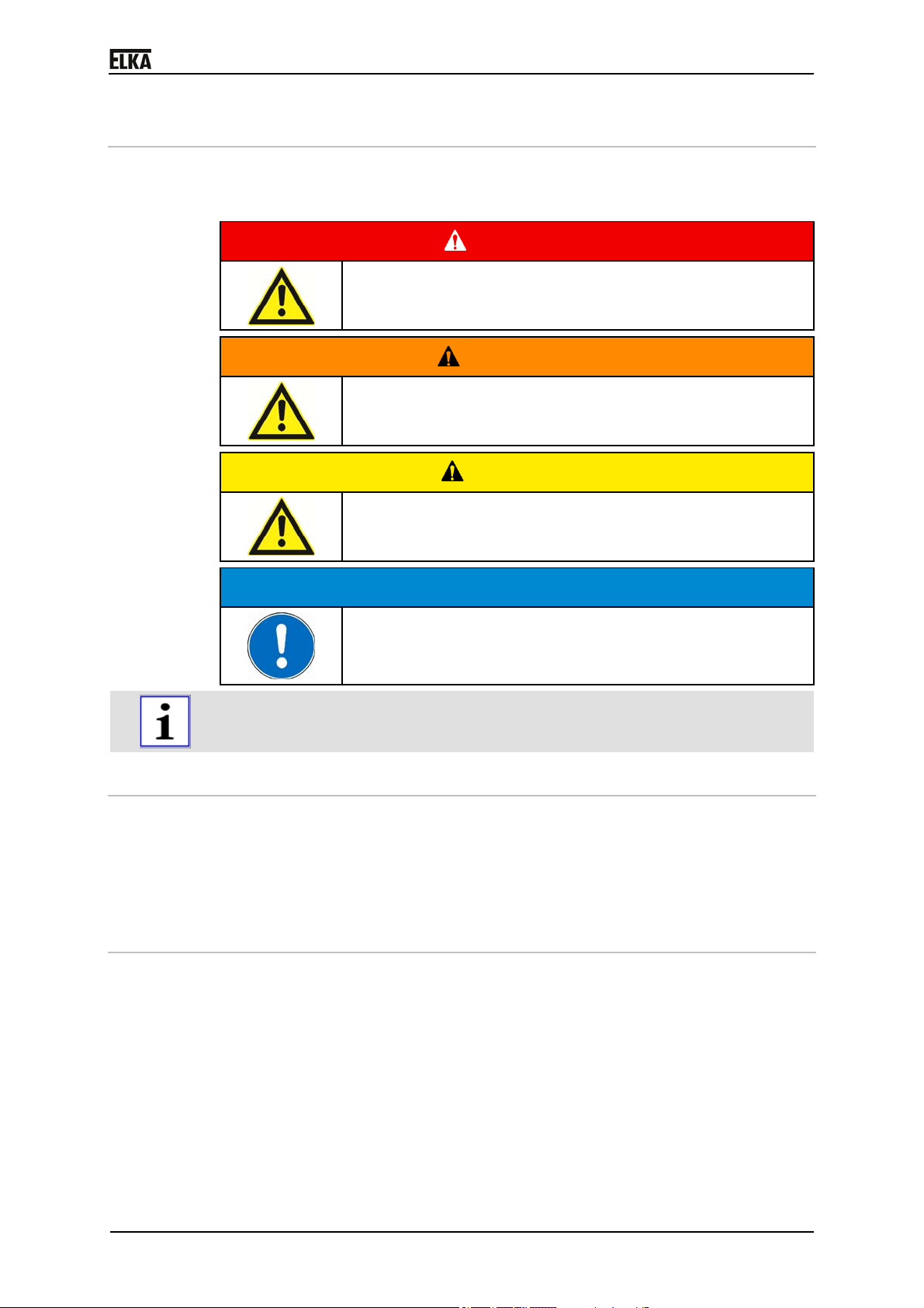
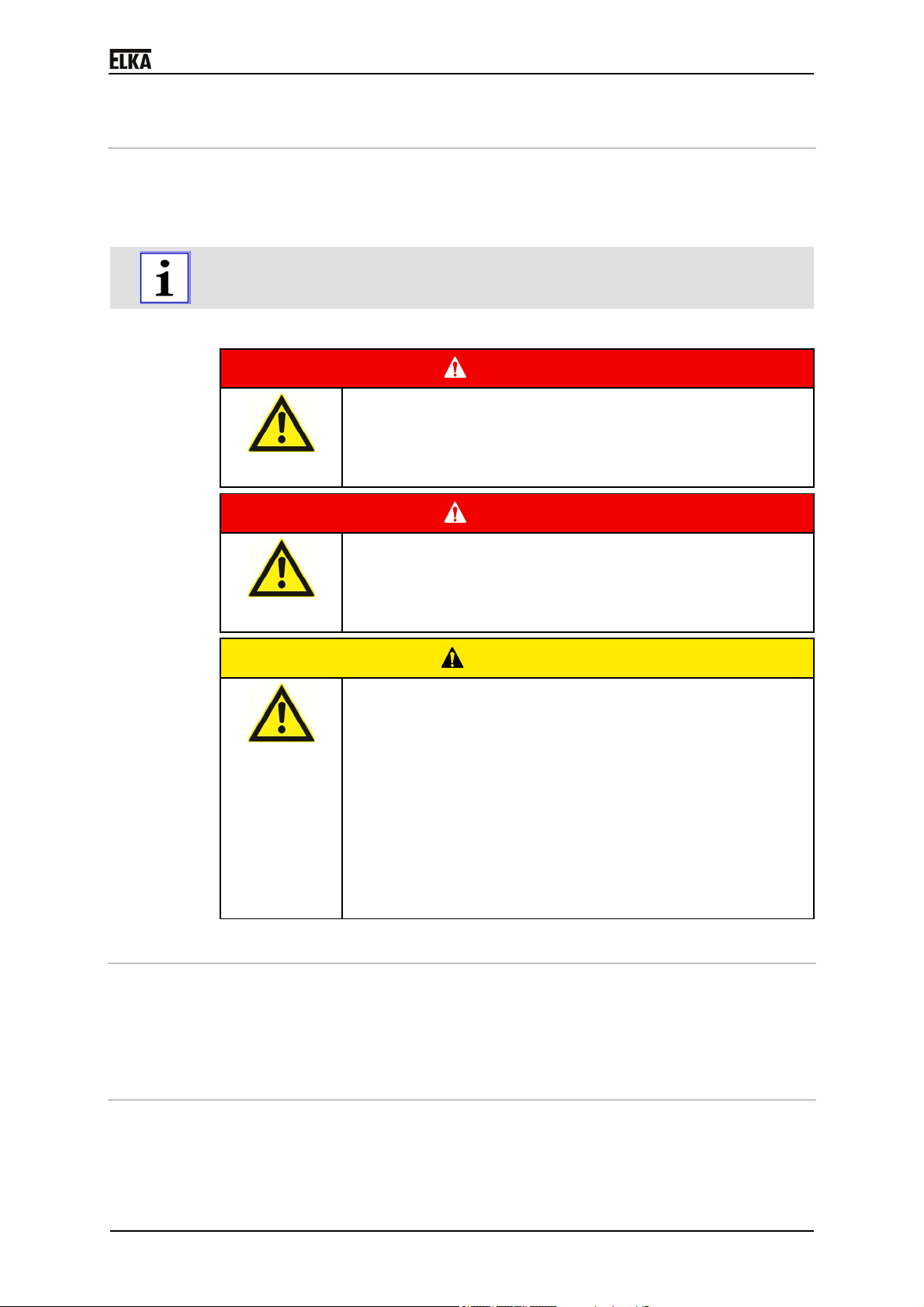
1.1.1 Symbol explanation
Remarks regarding the safety of persons and the gate opener itself are
marked by symbols. These remarks have to be absolutely observed in order to
avoid accidents and material damage.
…points to an imminent dangerous situation, which can
cause death or serious injuries if it is not avoided.
…points to a potentially dangerous situation, which can
cause death or serious injuries if it is not avoided.
…points to a potentially dangerous situation, which can
cause minor or slight injuries if it is not avoided.
P 2500 - P 500
DANGER!
WARNING!
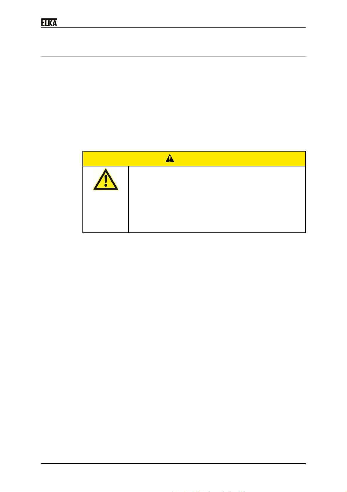
CAUTION!
CAUTION!
…points to a potentially dangerous situation, which can
cause property damage if it is not avoided.
REMARK!
Important notice for installation or functioning.
1.2 Copyright
The operating manual and the contained text, drawings, pictures, and other
depictions are protected by copyright. Reproduction of any kind – even in
extracts – as well as the utilization and/or communication of the content
without written release certificate are prohibited. Violators will be held liable for
damages. We reserve the right to make further claims.
1.3 Information regarding installation instruction
This document is to be used as installation instruction for partly completed
machinery (according to machinery directive 2006/42/EG, article 13, (2)).
4
Page 6

0
5
2 Safety
2.1 General notes on safety
The valid regulations and standards have to be observed during installation
and operation, e.g. DIN EN 13241-1, DIN EN 12445, DIN EN 12453 etc. Only
the use of spare parts made by the original manufacturer is allowed.
Do not put a defective barrier into operation.
After set-up (installation) every user of the equipment has to be instructed
about the operation and function of the barrier.
In order to reduce the risk potential related to the movement of the barrier
boom, additional optical and/or acoustical warning devices should be installed.
2.2 Notes on safety for the operation
Children and not instructed persons are not allowed to operate the barrier.
No persons, objects, or animals are allowed within the range of the barrier
movement during opening or closing.
Never reach into moving parts of the barrier.
Drive through the barrier only after complete opening.
The barrier has to be secured depending on the type of usage, corresponding
to the valid standards and regulations.
The safety devices have to be checked regularly for functioning according to
the standards and regulations, at least twice a year.
P 2500 - P 500
2.3 Notes on safety for the operation with radio remote
control
The radio remote control should only be used, if the area of movement of the
barrier is always completely visible by the operator and thus it is assured, that
no person, object, or animal is present within this range of movement.
The radio remote control transmitters have to be carefully kept, so that an
unintentional use is impossible.
Radio remote controls should not be operated at radio-technical sensitive
locations, like airports or hospitals.
Interferences by other (properly operated) radio communication installations,
which are used within the same frequency range, cannot be ruled out.
Page 7
0
6
2.4 Intended use – Vehicle traffic
The operational safety can only be ensured when the barrier is used as
intended.
After installation, the barriers of series P 2500-5000 serve as passage control
of vehicle paths exclusively of usage class Vehicular III and IV.
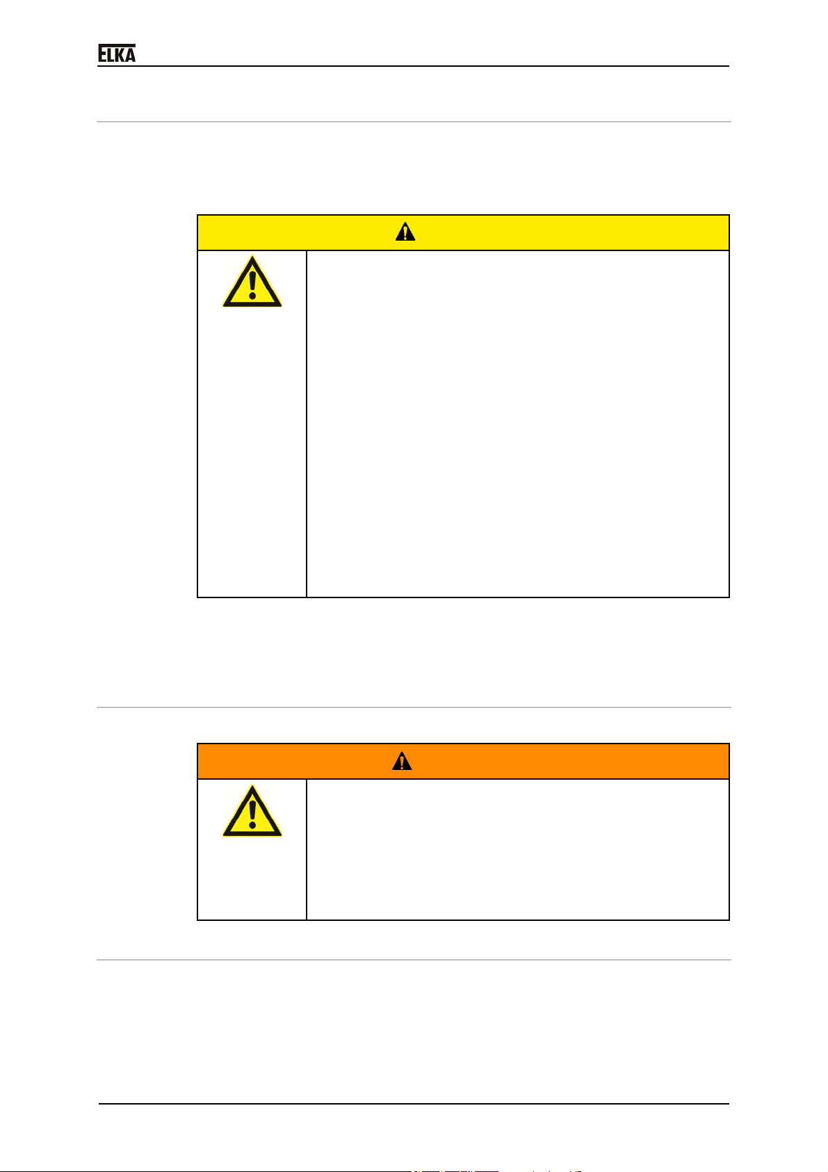
CAUTION!
Danger of impact and crushing!
With inadequate safety measures the movement of the
barrier boom can result in impact or crushing points
between the boom and solid objects within the movement
area.
In order to reduce the risk potential by a moving barrier
arm, additional safety devices of type B1 or B2
according to UL 325 (see table 31.1 of UL 325) should
be installed. The internal entrapment protection system
of the barrier P 2500-5000 corresponds to type A.
Two independent entrapment protections must be
installed before commissioning.
For the reversal of the gate, P541 must be set to "1"
andP542 must be set to "0". See "Installation and
operation instructions Part 2" sec. 2.2.5.6 and 2.2.5.7.
The gate operator must be equipped with an audio
alarm. See "Installation and operation instructions Part2"
The controller is a product component and serves to control the barrier.
Any use above and beyond the above mentioned use is prohibited and
constitutes improper use.
sec. 2.2.5.11.
P 2500 - P 500
2.5 Danger, which could emanate from the site of operation
The barriers P 2500-5000 operate with moving parts.
WARNING!
Rotating and/or linear movable components can cause
serious injuries.
Do not reach into moving parts or handle any moving
components during operation.
Turn the appliance off before any maintenance work,
repair work or other work and secure it against
2.6 Non-factory technical alterations and extensions
Non-factory technical alterations and/or extensions may result in hazards as
well as interfere with the function of the barrier.
unintentional restarting.
Page 8
0
7
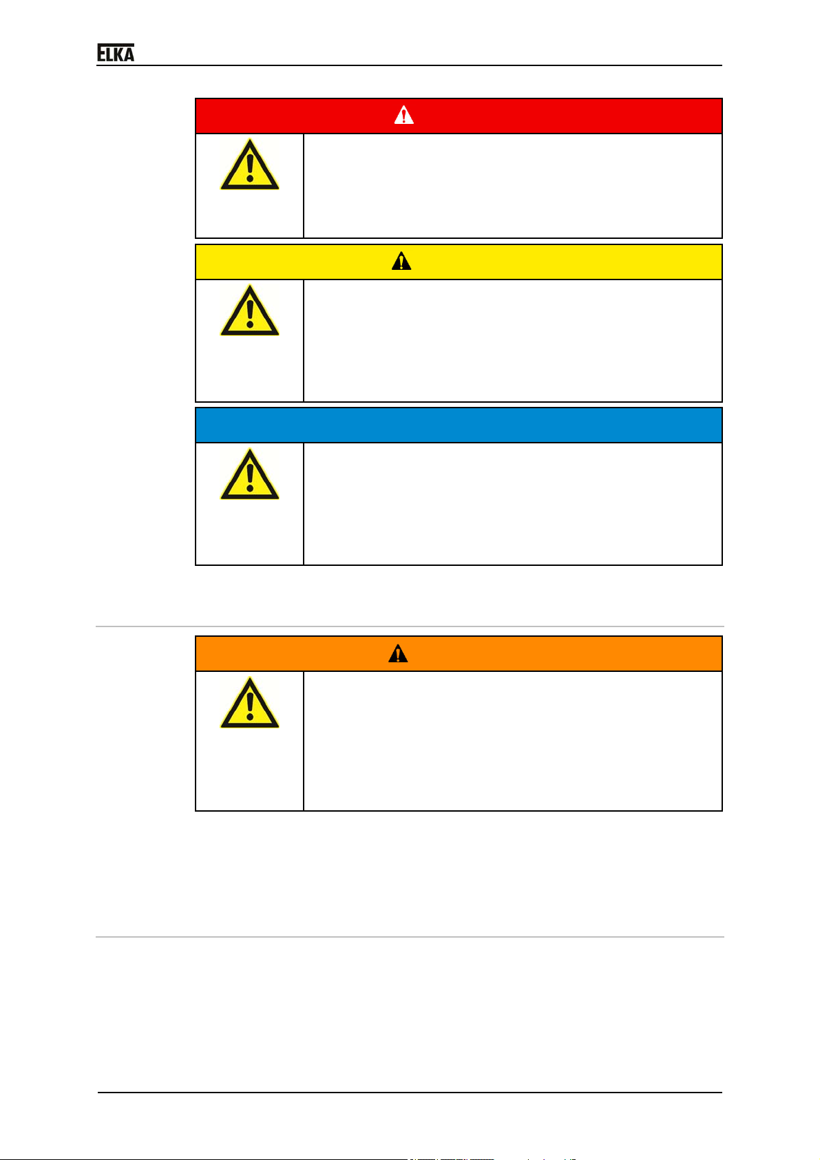
P 2500 - P 500
DANGER!
Danger through voltage!
Risk of death by electric shock!
Technical alterations may only be performed by skilled
personnel and only according to the manufacturer’s
instructions.
CAUTION!
Danger of injury through defective components!
Mechanical and electrical alterations can influence the
functioning of the barrier!
Technical alterations may only be performed by skilled
personnel and only according to the manufacturer’s
instructions.
CAUTION!
Malfunctioning of the barrier!
Mechanical and electrical alterations can influence the
functioning of the barrier!
Technical alterations may only be performed by skilled
personnel and only according to the manufacturer’s
instructions.
2.7 Personnel requirements – professional skills, knowledge
and qualifications
WARNING!
Risk of injury through inadequate qualification!
Improper handling during installation, maintenance, repair
work or dismantling can result in personal injury and/or
property damage.
Work during installation, maintenance, repair and
dismantling must be performed by skilled personnel
Specialist - is a person with suitable professional training, knowledge and
experience, who can recognize and avoid danger.
Instructed person - is a person, which was instructed in the operation and
use of the barrier.
only.
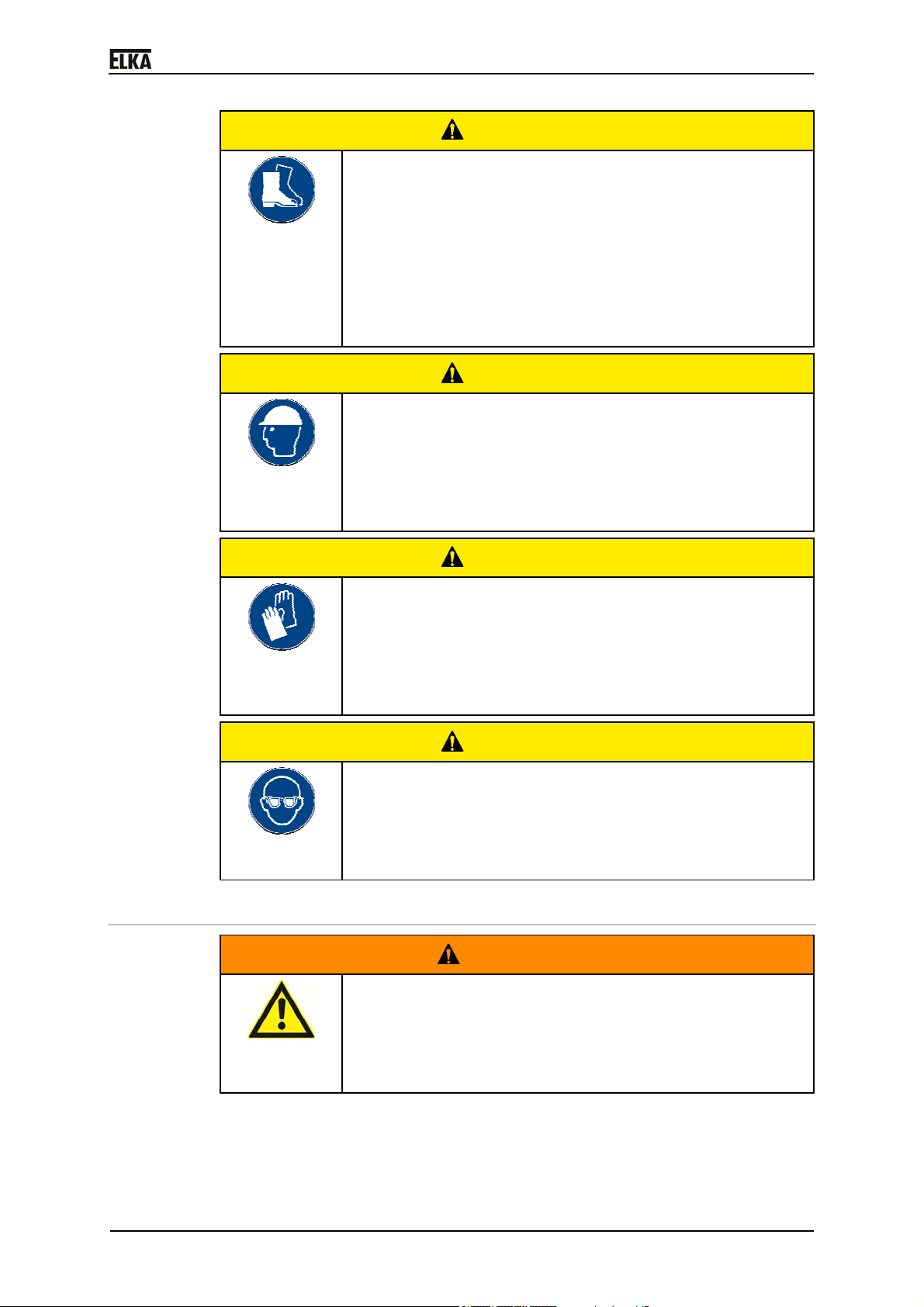
2.8 Personal protective equipment
During installation, maintenance, repair work and dismantling of the barrier
suitable personal protective equipment must be worn.
Page 9
0
8
P 2500 - P 500
CAUTION!
Bruising/jamming/driving over (e.g. by material
handling equipment, industrial trucks) the feet,
contusion by falling heavy objects, cutting injuries by
stepping into pointed/sharp objects.
Foot injuries
Wearing of suitable safety shoes during the installation,
maintenance, repair work and dismantling protects
against serious foot injuries with long-lasting
consequences.
CAUTION!
Falling heavy objects hitting the head
Head injuries
Wearing of a suitable safety helmet during the
installation, maintenance, repair work and dismantling
protects against serious head injuries with long-lasting
consequences.
CAUTION!
Cutting injuries resulting from pointed/sharp objects
Hand injuries
Wearing of suitable safety gloves during the installation,
maintenance, repair work and dismantling protects
against serious hand injuries with long-lasting
consequences.
CAUTION!
Injuries resulting from drilling chips or saw dust
Eye injuries
Wearing of suitable safety goggles during the installation
and repair work protects against serious eye injuries
with long-lasting consequences.
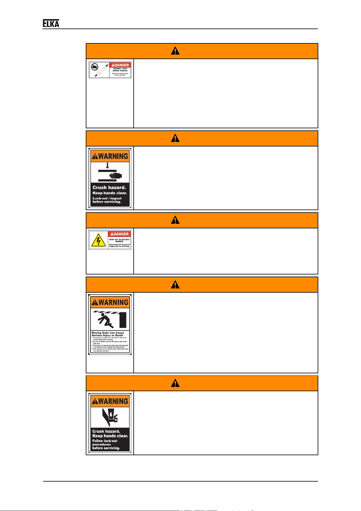
2.9 Hazard warnings inside the barrier
WARNING!
Personal injuries and/or property damage
Danger of accidents resulting from illegible or removed
safety instruction labels.
Immediately renew illegible or removed safety
guidelines.
Page 10
0
9
P 2500 - P 500
WARNING!
Danger of impact and crushing!
During the barrier movement, energy is saved in the
springs. The springs are not tight and thus energy-free only
in barrier position OPEN.
Mount and dismount the springs in barrier position
OPEN only. If necessary open the barrier by mechanical
emergency release and move the barrier manually into
position OPEN.
WARNING!
Risk of crushing
During the barrier movement crushing points arise at many
points of the barrier mechanics.
Before installation, maintenance or repair work at the
barrier mechanics turn the power supply off and secure
it against unintentional restarting.
WARNING!
Danger through voltage!
Danger of an electric shock.
Before installation, maintenance or repair work at the
barrier mechanics turn the power supply off and secure
it against unintentional restarting.
WARNING!
Danger of impact!
Accident hazard by barrier boom movement.
Keep a sufficient safety distance (min. 19.7in) during the
barrier movement
Children are not allowed to play within the barrier area
or operate the barrier.
Opening and closing of the barrier is only allowed with
the barrier in view. No persons or objects are allowed in
the danger zone.
WARNING!
Danger of crushing!
Crushing points arise at many areas of the barrier
mechanics during the barrier movement.
Disconnect the barrier from the power supply before
installation, maintenance or repair work at the barrier
mechanics and secure against reactivation.
Page 11

0
0
P 2500 - P 500
WARNING!
Improper operation, inadequate maintenance or non
observance of the notes on safety!
Improper operation, inadequate maintenance or non
observance of the notes on safety indicated in this manual
may lead to danger to persons or material damage.
Should a part of the manual be unclear or should any
instructions, procedures or safety guidelines not be
clearly comprehensible, please contact ELKA
Torantriebe GmbH u. Co. Betriebs KG, before putting
the barrier into operation.
1
Page 12
0
3 Transportation and storing
3.1 Transportation inspection
The shipment has to be inspected for transportation damage immediately after
receipt. In case of any damage record the type and extent on the delivery
receipt or refuse acceptance.
Inform ELKA-Torantriebe immediately in the event of damage.
In case the above points are not observed claims will be denied due to
insurance regulations.
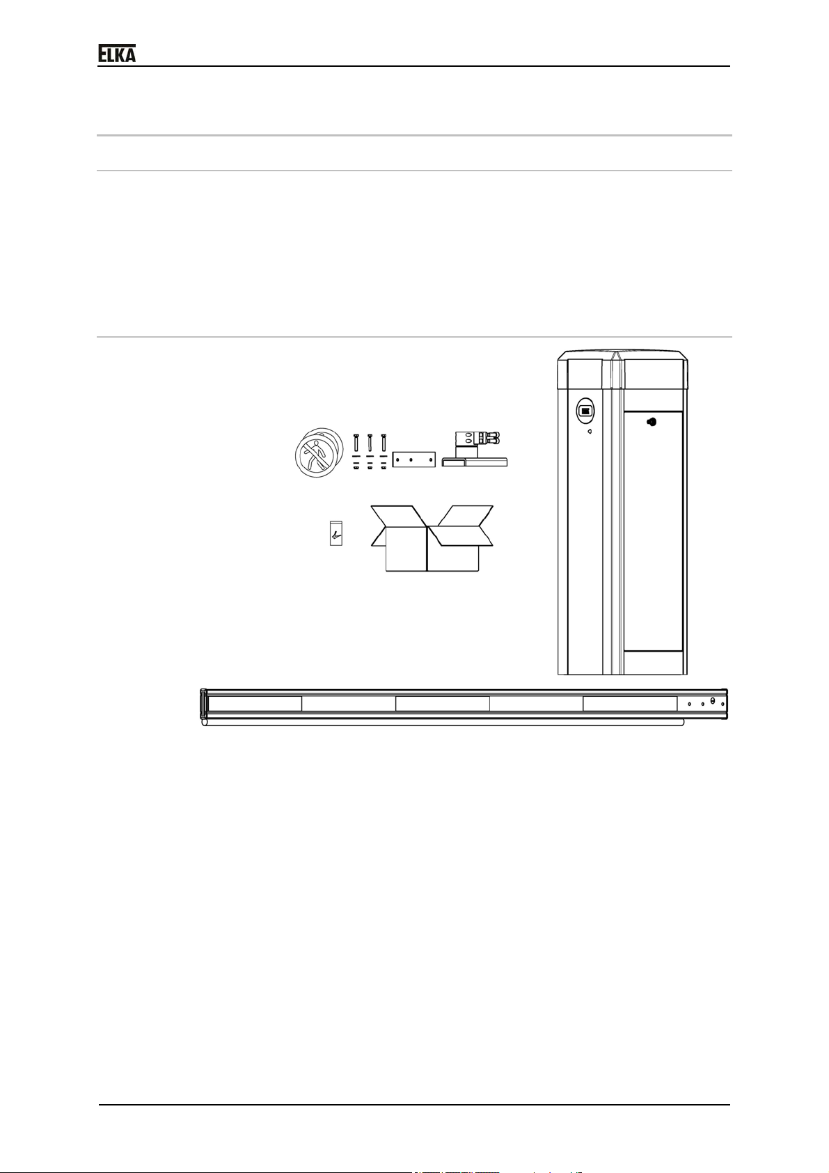
3.2 Scope of delivery P 2500-5000
P 2500 - P 500
Drawing 1
Scope of delivery:
1x barrier model P 2500-5000
1x barrier boom
2x keys (in a pouch) for the access panel
1x accessory box with:
- 2x warning signs "No passage for pedestrians"
- 3x plastic screws or 3x steel screws for P 5000 incl. washers and nuts
for the boom connection
- 1x boom connector incl. reinforcement plate and fastening screws
11
Page 13
0
2
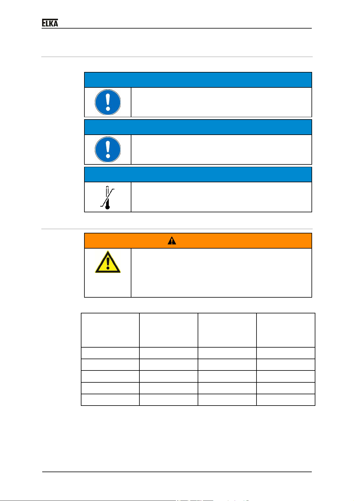
3.3 Storing
The barrier has to be stored as follows:
P 2500 - P 500
CAUTION!
Do not expose the barrier to aggressive substances.
Do not expose the barrier to heat sources.
Storage temperature -30°C to +70°C / -22°F to +158°F.
3.4 Lifting heavy loads
Risk of injury by lifting heavy loads!
Lifting heavy loads may cause serious injuries.
Never lift the barrier single-handedly.
To lift the barrier, use a suitable lifting device.
Barrier model Weight barrier
Wear suitable safety shoes.
without boom
[lb]
CAUTION!
CAUTION!
WARNING!
Weight standard
boom / round
boom
[lb]
Total(with
standard boom /
round boom)
[lb]
P 2500 125.7 8.4 / 4.4 134.1 / 130.1
P 3000 127.8 9.9 / 5.3 137.7 / 133.1
P 3500 127.8 11.0 / 6.2 138.8 / 134,0
P 4000 130.1 12.8 / 7.1 142.9 / 137.2
P 5000 132.3 22.1 / --- 154.4 / ---
Table 1
1
Page 14
0
3
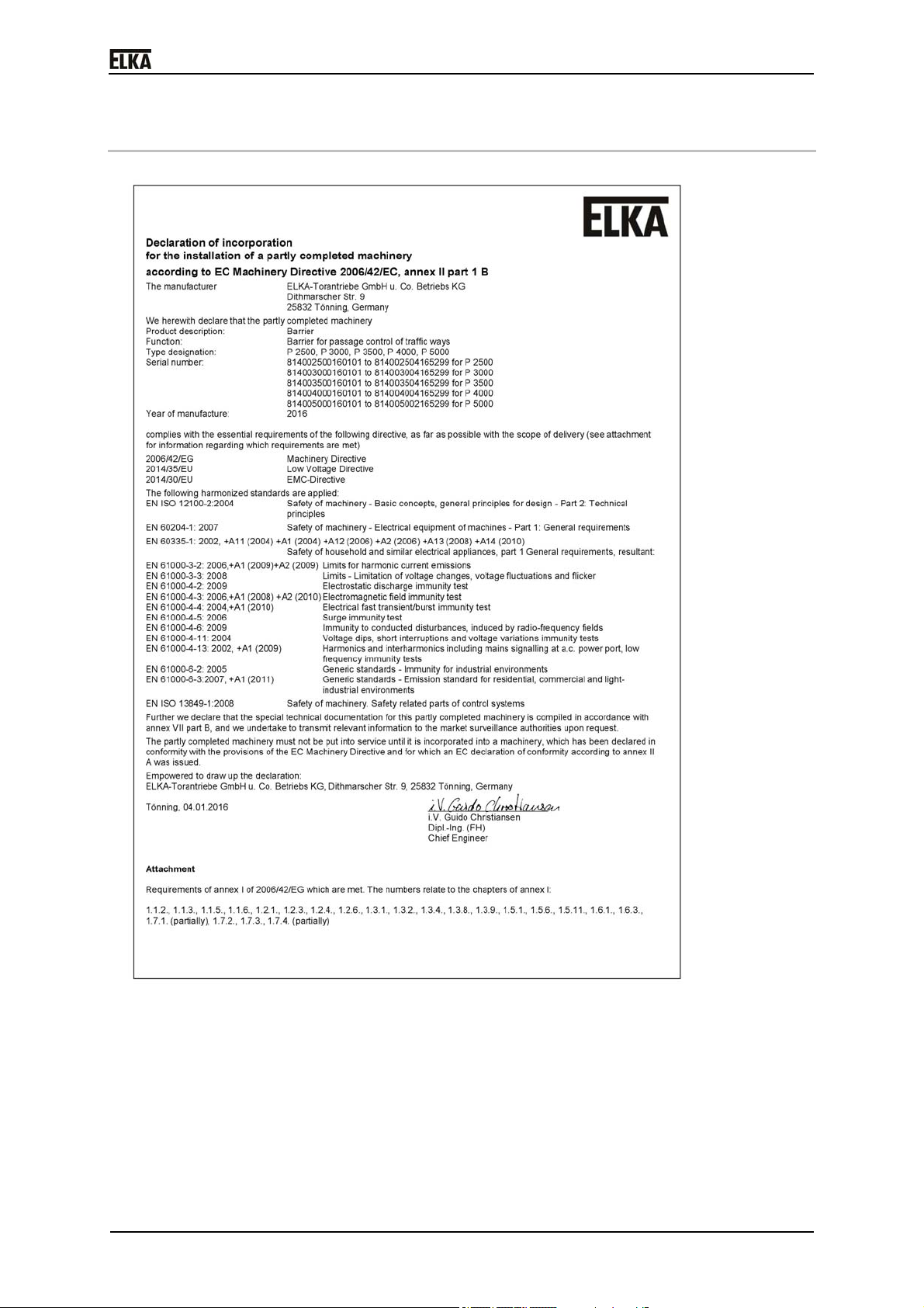
4 Declaration of incorporation
P 2500 - P 500
Drawing 2
1
Page 15
0
P 2500 - P 500
4.1 Installation information for partly completed machinery
The partly completed machinery must not be put into service until the
final machinery into which it has to be incorporated has been declared
inconformity with the provisions of the machinery directive.
The safety functions of the controller comply with EN ISO 13849-1:2008 Kat.2
PLc.
DANGER!
Not-disengeable power supply
Risk of death by electric shock
According to EC Directive 2006/42/EG the mains supply
has to be equipped with an all-pole circuit breaker.
DANGER!
Danger through voltage!
Danger of an electric shock.
Only certified electricians should connect the barrier to
the mains supply.
CAUTION!
Danger of crushing and shearing!
With inadequate safety measures the movement of the
barrier boom can result in impact or crushing points
between the boom and solid objects within the movement
area.
According to DIN EN 12453, for an application with
pedestrian traffic, depending on the type of use and type
of activation, suitable safety devices have to be installed
additionally, in order to provide the minimum level of
protection.
4.2 Declaration of conformity
Minimum clearances to solid objects must be observed.
After the installation an EG-declaration of conformity according to ECmachinery directive 2006/42/EG for the complete system has to be issued by
the person responsible for the integration (according to product standard DIN
EN 13241-1).
4.3 Name plate
The name plate of the barrier is attached at the inside front of the barrier
housing.
14
Page 16
0
5
5 Function description
Barriers serve as passage control of vehicle paths. By raising and lowering of
the barrier boom the passage is granted or obstructed.
For a boom length of 157.48in we recommend the use of a fixed or swinging
support, for a boom length of more than 157.48in the use of a fixed or
swinging support is mandatory.
The controller offers the possibility to activate the barrier by radio remote
control.
The controller is able to observe the max. permitted force which was set
before in the learning sequence. If during the closing movement more force is
needed, the barrier reverses. Additionally several different safety features, e.g.
photoelectric barriers, can be connected.
CAUTION!
Danger of impact and crushing!
With inadequate safety measures the movement of the
barrier boom can result in impact or crushing points
between the boom and solid objects within the movement
area.
In order to reduce the risk potential related to the
movement of the barrier boom, additional optical and /
or acoustic warning devices should be installed.
P 2500 - P 500
1
Page 17

0
6
6 Technical data P 2500-5000
Range of application
P 2500 - P 500
Application for…
Parking garages, parking areas and camping sites
Company entrances
Drive pulse
from...
TCP/IP
RS485
Push button, card reader, desktop panel etc.
Transmitter (radio remote control)
Induction loops
Safety
Force monitoring for barrier CLOSE
Emergency release / vandalism protection
Internal evaluation for safety contact profile (8.2kOhm)
Connection of external safety systems
Table 2
General data
Supply voltage 120VAC
60Hz
Current consumption Max. 2.8A
Duty cycle 100%
Temperature range -30°C to +50°C / -22°F to +122°F
Controller MO 24
Housing dimensions (L/W/H) 14.14 x 11.81 x 43.34in
Foundation (frost-free) 21.65 x 19.96 x 31.50in
Boom connector Left or right
Housing Aluminium
Mechanics Steel, galvanized
Sound pressure level (distance 1m) ≤ 60 dB(A)
Degree of protection IP 54
Protection class 1
Table 3
1
Page 18

0
7
P 2500 - P 500
Model-related data P 2500 P 3000 P 3500 P 4000 P 5000
Power consumption, max. [W] 180 85 80 85 195
Opening and closing time -
1.3 1.8 2.5 3.8 4.5
standard, approx. [s]
Opening and closing time -
1.8 2.5 3.8 4.5 5.5
slow, approx. [s]
Opening and closing time -
0.9 1.3 1.8 2.8 3.8
fast, approx. [s]
Max. boom length [in] 98.41 118.11 137.80 157.48 196.85
Effective boom length [in] 89.76 109.45 129.13 148.82 188.19
Power reversal yes yes yes yes yes
Table 4
1
Page 19

0
8
7 Installation P 2500-5000
7.1 Tools
Quantity Description
2 Open-end wrench 13mm
1 Open-end wrench 16mm
1 Open-end wrench 17mm
1 Open-end wrench 18mm
1 Open-end wrench 19mm
1 Allen key 6mm
1 Torque wrench (1-25Nm) 1/4"-square head
1 Bit 1/4", 13mm
1 Torque wrench (40-200Nm) 3/4"-square head
P 2500 - P 500
1 Bit 3/4", 10mm,
Length 100mm
1 Bit 3/4", 19mm,
Length 100mm
1 Bit 3/4", 10mm,
hexagon socket,
length 100mm
1 Right-angle screwdriver for hexagon socket
4mm, long model
screws
1 Right-angle screwdriver for hexagon socket
6mm, long model
screws
1 Screwdriver 0,6 x 3,5mm
1 Screwdriver PH2 x 100
1 Cutter knife 18mm
1 Level
Table5
1
Page 20

0
9
7.2 Mounting dimensions
P 2500 - P 500
Drawing 3
1
Page 21

0
0
7.3 Foundation
Basic requirements
Keep a safety distance of min. 2ft (24in) between all moving barrier parts
and surrounding objects like walls, fences etc. Please check the following
drawing.
When preparing the foundation consider the alignment and distance
related to a (optional) fixed support (see drawing Drawing 3.
P 2500 - P 500
Drawing 4
a = min. 2ft (24in)
2
Page 22

0
P 2500 - P 500
Empty conduits
Use separate conduits for the power line and the control leads.
Use an additional (separate) conduit for each induction loop.
The distance between the conduits should be as large as possible.
Drawing 5
Requirements regarding the foundation
A minimum concrete strength class of C20/25 (or higher)
The use of heavy duty anchor bolts (M12).
Observe the foundation dimensions quoted in this manual. The installation
distance between the barrier housing and the foundation edge has to be
approx. 100mm.
WARNING!
Risk of injury by insufficient fastening!
Tilting barrier housings can result in severe injuries.
Before installation ensure a safe stand of the barrier
housing.
Do not lean the barrier boom against a wall or similar
before installation. Store the boom horizontally only.
Install the barrier housing as specified.
Use the recommended heavy duty anchor bolts M12, at
least M10 is required.
During maintenance check the housing for correct
fastening on the foundation.
21
Page 23

0
2
P 2500 - P 500
Drawing 6
1 Fastening point (10.45 x 7.99)
2 Fastening point, re-adjustable (9.06 x 7.09in)
3 Clearance for cable entry (empty conduits) (7.87 x 5.75in)
4 Drilling template
5 Foundation
6 Direction roadway
WARNING!
Danger of injury by incorrect fixation of the barrier
housing on the foundation!
Loosening of the anchor bolts from the foundation.
During the fastening of the barrier obey the minimum
distance of the heavy duty anchor to the edge of the
foundation.
2
Page 24

0
3
7.4 Opening / closing the housing
WARNING!
Rotating and/or linear movable components can cause
serious injuries.
Do not reach into moving parts or handle any moving
components during operation.
Turn the appliance off before any maintenance work,
repair work or other work and secure it against
Open the housing with the access panel key. The key is located in the
accessory box.
Removing the housing hood:
unintentional restarting.
P 2500 - P 500
Drawing 7
1. Remove the hood by pressing the release levers to the outside (1). The
hood raises itself.
2. Now take the hood off upwards - using both hands (2).
2
Page 25

0
P 2500 - P 500
Installing the hood:
Drawing 8
1. Using both hands place the hood on the housing by first pressing he rear
guidance points (1), then the front guidance points (2).
2. The hood snaps into place with an audible click.
7.5 Boom connector
1. The boom connector can be mounted left or right (factory setting is
right).To fasten the boom connector, plug it without the clamping piece on
the main shaft. Pay attention to a perfect fit of the shaft seal at the
housing. Now connect the clamping piece using the four screws (M12x30
ISO4762). Tighten the screws only so far that an alignment of the boom
connector on the main shaft is still possible.
24
Page 26

0
5
P 2500 - P 500
Drawing 9
2. The barrier mechanics is preset at the factory so that the barrier boom can
perform a 90° - movement from the vertical to the horizontal position. The
barrier is delivered in open (vertical) position. The drive lever is over the
dead center at the mechanical stop (see drawing below). If necessary,
correct the position by pulling the drive lever (1) in direction OPEN towards access panel/roadway (arrow 2).
Drawing 10
3. Adjust the boom connector vertically using a water-level.
2
Page 27

0
6
Drawing 11
4. Now retighten the four screws (M12x30 ISO 4762) at the clamping piece
with 88.5 lbf ft.
7.5.1 Installation – Boom connector left side
The barrier models TF 1203/0001-1204/0001 and XP 1203/0001-1204/0001
are prepared at the factory to mount the boom on the right side. At the left side
a cap is mounted to cover the main shaft opening.
Converting from barrier boom right to barrier boom left:
1. Remove the barrier hood.
2. Detach the cover cap at the left housing side as described in the following
drawing. First pull the spring sheet upwards (1), then turn the cover cap
approx. 60° (2) and pull it upwards (3).
P 2500 - P 500
Drawing 12
3. Disconnect the boom connector from the right side, if already mounted.
Connect it to the left side.
4. Mount the cover cap and the spring sheet at the right housing side.
2
Page 28

0
7
All drawings, tables and descriptions in this installation manual refer to the
factory-set (pre-) mounting of the boom holder at the right side.
7.6 Barrier boom
1. Remove all balancing springs from the spring assembly (see below
drawing).
P 2500 - P 500
Drawing 13
2. Turn the barrier mechanics (at the boom connector) into position CLOSED
(1). If necessary support the movement by pushing the drive lever in
direction CLOSED (2).
Drawing 14
3. Position the barrier boom with the reinforcement plate at the boom
connector. Make sure that the profile of the barrier boom fits tightly
(without play) at the boom connector.
2
Page 29

0
8
P 2500 - P 500
Drawing 15
4. Barriers P 2500 - P 4000:
Connect the barrier boom to the boom connector using the plastic screws
M8x50. Tighten the fastening nuts with a max. torque of 1.3lbf ft.
Use only the specific plastic screws M8x50. Screws with another specification
might prevent the tearing off of the barrier boom (predetermined shearing
point).
5. Barriers P 5000:
Connect the barrier boom to the boom connector using the screws M8x70.
Tighten the fastening nuts with a max. torque of 14.8lbf ft.
Due to the use of the steel screws M8x70 at the barrier P 5000 the
predetermined shearing point and such the vandalism protection is not
applicable – other than with the barriers P 2500 - P 4000.
7.7 Balancing springs
1. Activate the mechanical emergency release of the barrier and place the
barrier boom manually in position OPEN.
2. Mount the number of balancing springs according to the boom length and
additional (optional) equipment if applicable (see table below).
Please note that for the different versions two types of pressure springs (F1.1
and F1.2) are used.
Model
P 2500 2x
P 2500 with 2x 3x --- --- --- --- ---
2
Boom length [in]
78.74 98.41 118.11 137.80 157.48 177.17 196.85
F1.1
2x
F1.1
--- --- --- --- ---
Page 30

0
9
P 2500 - P 500
Model
articulated
Boom length [in]
78.74 98.41 118.11 137.80 157.48 177.17 196.85
F1.1 F1.1
boom
P 2500 with
round boom
2x
F1.1
P 3000 2x
F1.1
P 3000 with
articulated
2x
F1.1
boom
P 3000 with
round boom
2x
F1.1
P 3500 2x
F1.1
P 3500 with
articulated
2x
F1.1
boom
P 3500 with
round boom
2x
F1.1
2x
F1.1
2x
F1.1
3x
F1.1
2x
F1.1
2x
F1.1
3x
F1.1
2x
F1.1
--- --- --- --- ---
3x
--- --- --- ---
F1.1
3x
--- --- --- ---
F1.1
2x
--- --- --- ---
F1.1
3x
F1.1
3x
F1.1
2x
F1.1
4x
F1.1
4x
F1.1
3x
F1.1
--- --- ---
--- --- ---
--- --- ---
P 4000 2x
F1.1
P 4000 with
--- --- --- 2x
swinging
2x
F1.1
3x
F1.1
3x
F1.1
F1.2
support
P 4000 with
articulated
2x
F1.1
2x
F1.1
3x
F1.1
4x
F1.1
boom
P 4000 with
round boom
P 4000 with
round boom
2x
F1.1
2x
F1.1
2x
F1.1
3x
F1.1
--- --- --- 3x
F1.1
and with
swinging
support
P 5000 --- --- --- 2x
F1.2
P 5000 with
swinging
--- --- --- 3x
F1.2
support
2x
F1.2
2x
F1.2
2x
F1.2
3x
F1.1
2x
F1.2
3x
F1.2
3x
F1.2
--- ---
--- ---
--- ---
--- ---
--- ---
3x
F1.2
3x
F1.2
4x
F1.2
4x
F1.2
Table 6
Pressure spring type F1.1 = Balancing spring
Wire diameter 0,2in
For barriers up to 137.79in boom length
2
Page 31

0
0
P 2500 - P 500
Pressure spring type F1.2 = Balancing spring
Wire diameter 0,24in
For barriers above 137.79in boom length
3. During installation of the balancing springs please observe the correct
positioning in the spring assembly (see drawing below – positions of the
pressure springs on the support plate).
Drawing 16
a = 2 springs
b = 3 springs
c = 4 springs
It is not permitted to operate the barrier with only one spring mounted!
4. Activate the mechanical emergency release of the barrier and place the
barrier boom manually in position 45°. The barrier boom has to level itself
in this position. If necessary, correct the boom position by
tightening/loosening of the spring tension.
Drawing 17
3
Page 32

0
P 2500 - P 500
Adjusting the spring tension:
WARNING!
Danger of impact and crushing!
During the barrier movement, energy is saved in the
springs. The springs are not tight and thus energy-free only
in barrier position OPEN.
Mount and dismount the springs in barrier position
OPEN only. If necessary open the barrier by mechanical
emergency release and move the barrier manually into
position OPEN.
WARNING!
Risk of crushing
During the barrier movement crushing points arise at many
points of the barrier mechanics.
Before installation, maintenance or repair work at the
barrier mechanics turn the power supply off and secure
it against unintentional restarting.
Drawing 18
Tightening the spring tension: Turn the clamping nut (a) clockwise (1). The
boom moves in direction (1).
Loosening the spring tension: Turn the clamping nut (a) anti-clockwise (2).
The boom moves in direction (2).
31
Page 33

0
2
7.8 Opening and closing times
The opening and closing times of the barriers are factory-set to standard
values based on the model:
P 2500 = approx. 1.3 seconds
P 3000 = approx. 1.8 seconds
P 3500 = approx. 2.5 seconds
P 4000 = approx. 3.8 seconds
P 5000 = approx. 4.5 seconds
The opening and closing times of the barriers can be changed in the learning
sequence of the controller MO 24 under sequence point P101.
Sequence point P101 = 0 = fast
Sequence point P101 = 1 = standard (factory setting)
Sequence point P101 = 2 = slow
Model-related data P 2500 P 3000 P 3500 P 4000 P 5000
P 2500 - P 500
Running time –slow [s] approx.
1.8
Running time –standard [s] approx.
1.3
Running time – fast [s] approx.
0.9
Table 7
approx.
2.5
approx.
1.8
approx.
1.3
approx.
3.8
approx.
2.5
approx.
1.8
approx.
4.5
approx.
3.8
approx.
2.8
approx.
5.5
approx.
4.5
approx.
3.8
3
Page 34

0
3
7.9 Accessories
7.9.1 Swinging support P 4000 - P 5000
1. Move the barrier boom into the horizontal position.
P 2500 - P 500
Drawing 19
2. The bottom part ‘C’ can be connected at the approximate length using the
screws ‘B’.
3. Remove approx. 39.5in of the rubber tube under the boom and push the
securing pieces ‘A’ of the swinging support into the notch of the barrier
boom. Secure the swinging support using the two hexagon head screws.
Drawing 20
4. Push the rubber tube back into the notch and cut off the protruding part.
5. A fine adjustment of the swinging support height can now be made at the
foot ’D’.
6. Screw an M4mm screw into the whole ‘E’ and loosen the M10 stop nut at
the foot ’D’.
7. The foot can now be screwed to the appropriate position. Tighten the M10
stop nut upwards against the aluminium bushing. Remove the M4 screw.
3
Page 35

0
Drawing 21
Due to the additional load of the swinging support, the number of balancing
springs has to be adjusted. Install the correct number of balancing springs
depending on the boom length according to the table on page 29.
7.9.2 Fixed support P 4000 - P 5000
1. Mount the fixed support on a suitable foundation.
2. Observe the alignment and the distance to the barrier (see drawing below).
3. Mount the fixed support on the foundation.
4. Pay attention to the following points during installation. When the barrier is
closed:
a. the barrier boom has to be positioned in the middle of the support fork.
b. the profile end of the barrier boom must not protrude beyond the
support fork.
c. the barrier boom remains approx. 0.8-1.2in above the rubber insert.
P 2500 - P 500
34
Page 36

0
5
P 2500 - P 500
Drawing 22
7.9.3 Fixed support with electromagnet
1. Mount the fixed support on a suitable foundation.
2. Observe the alignment and the distance to the barrier (see drawing below).
3. Mount the fixed support on the foundation.
Mounting the anchor plate to the barrier boom:
1. Connect the flexible lead from the magnet with the cable of the barrier.
There is enough room at the lower part of the support for a junction box.
2. Fit the support fork onto the foot and secure it at the required height.
3. Remove a part of the rubber profile from the bottom part of the boom.
4. Push one of the securing pieces into the notch of the closed barrier boom.
5. Now insert the anchor plate into the notch until it is exactly above the
magnet.
Drawing 23
3
Page 37

0
6
P 2500 - P 500
6. Now insert the second securing piece.
7. Push both securing pieces against the anchor plate and secure them with
the screws.
Connecting the electromagnet in the barrier:
Drawing 24
Following the connection of an electromagnet as well as the required
parameter changes in the controller are described. As an example the multifunctional relay 4 (MULTI4) and as power supply for the standard
electromagnet the internal 24Vdc of the MO 24 is used.
CAUTION!
Over-voltage when switching off an inductive DC load!
Defect of the controller or the external (on-site) DC voltage
source by overvoltage!
Always connect the free-wheeling diode R1 (type
1N4004), as shown in the drawing, when using an
1. Connect the electromagnet to the terminal row, as shown in the drawing.
Use a minimum cable cross-section of AWG 16. The cable length shall not
exceed a length of 65.61ft.
2. Connect the multi-functional relay 4 to 24Vdc.
3. Activate the pre-warning time in the learning sequence of the controller
MO 24 under sequence point P302. Select a time longer than 1.5 seconds.
4. Activate the multi-functional relay 4 in the learning sequence under
sequence point P504. Select the operating mode “10” - The multifunctional relay is activated, when the barrier is closed. During the prewarning before opening the relay is already switched off.
Procedure:
1. The barrier is closed. On receipt of a signal to open the multi-relay is
switched off and it loses the residual magnetism during the pre-warning
time.
2. The barrier opens after the set pre-warning time (P302) has elapsed.
3. The barrier is open. After a closing impulse the multi-functional relay (the
magnet) is switched on only when the end position CLOSED is reached.
electromagnet.
3
Page 38

0
7
7.9.4 LED boom lighting
Drawing 25
The following instruction explains the connection of the LED boom lighting as
well as the necessary parameter changes in the controller. As an example the
multi-functional relay 4 (MULTI4) and the multi-functional relay 5 (MULTI5) are
being used for the activation as well as the internal 24Vdc power supply of the
controller MO 24 as power supply.
1. Connect the supply line of the LED boom lighting to the terminal row X1,
as shown in the drawing. Use a min. wire cross section of AWG 20.
2. Connect the multi-functional relays 4 and 5 to ground (Gnd) as shown.
3. Activate the multi-functional relay 4 under the sequence point P504 in the
learning sequence of the controller. Select the operating mode “9”. The
multi-functional relay is activated when the barrier is open. During prewarning before closing the relay is already deactivated.
4. Activate the multi-functional relay 5 under the sequence point P505 in the
learning sequence of the controller. Select the operating mode “10”. The
multi-functional relay is activated when the barrier is closed. During prewarning before opening the relay is already deactivated.
Procedure:
1. The barrier is closed. The LED boom lighting is RED. When an opening
impulse is given, the multi-functional relay 4 is switched off.
2. The barrier opens. The LED boom lighting is off.
3. The barrier is open. The LED boom lighting is GREEN. When a closing
impulse is given, the multi-functional relay 5 is switched off.
P 2500 - P 500
3
Page 39

0
8
7.10 Emergency release
P 2500 - P 500
Drawing 26
During a power failure open the barrier by pulling the release lever. Now, the
barrier can be opened by hand.
7.11 Vandalism
WARNING!
By pressing the boom up or down the correct position of the
boom may be moved (missadjusted - vandalism!).
Unforeseeable danger spots may arise.
If the position of the boom is misadjusted, the correct
setting of the barrier boom must be restored.
Drawing 27
3
Page 40

0
9
P 2500 - P 500
WARNING!
Rotating and/or linear movable components can cause
serious injuries.
Do not reach into moving parts or handle any moving
components during operation.
Turn the appliance off before any maintenance work,
repair work or other work and secure it against
unintentional restarting.
WARNING!
Danger due to uncontrolled movements of the
mechanics by pre stressed springs!
Parts of the mechanics can move through the spring tension
and pinching body parts.
BEFORE adjusting the boom position, the barrier
boom must be moved electrically or by hand
(emergency release) in the position OPEN.
Drawing 28
Restoring of the correct barrier boom position
1. Loosen the clamping screw of the drive lever M (Pos. 5).
2. Set manually the boom in position OPEN.
3. Rotate the gear box shaft (Pos. 13) up to the stop.
4. A distance (A) of 2mm must be set between the drive lever F and the cut in
the main plate. If this is not the case, loosen the two clamp bolts of the
drive lever F and set the distance to about 2mm. Tighten the clamping
screws of the drive lever F (88.5lbf ft).
3
Page 41

0
0
P 2500 - P 500
Drawing 29
5. Tighten the clamping screw of the drive lever M to the specified torque.
The torque is adapted to the mechanics and is marked on the label (B).
6. Turn on the barrier (power supply). Check the faultless running and the
correct positions (OPEN and CLOSE).
4
Page 42

0
8 Terminal row
8.1 Interior view
P 2500 - P 500
Drawing 30
Pos. Description
1 Controller MO 24 (with housing and cover)
2 Supply voltage 24VDC
3 Motor connection
4 Terminal row
5 Fixing clamp for power- and signal lines
6 Top hat rail for accessories (optional or on-site)
7 On-off switch
8 Main terminals (L1, N and PE)
Table 8
8.2 Mains connection
Danger through voltage!
Danger of an electric shock.
Only certified electricians should connect the barrier to
the mains supply.
DANGER!
41
Page 43

0
2
P 2500 - P 500
DANGER!
Danger through voltage!
Danger of an electric shock!
Observe the following connection instructions.
Connection instructions:
For a permanent electrical installation please observe the country-specific
regulations.
The connection terminals are designed for a rated cross-section per
terminal of AWG 22 to AWG 14.
The supply lead cross-section used has to be suitable for the load and
comply with the local regulations.
DANGER!
Danger through voltage!
Danger of an electric shock!
Connect the protective conductor of the mains lead
directly to the protective conductor terminal (PE) at the
barrier housing.
1. For the connection to the terminals and the protective conductor terminal
(PE) the flexible mains lead must have the following dimensions:
Drawing 31
1 Lead N, length a = 1.81in incl. conductor sleeve
2 Lead L1, length b = 2.17in incl. conductor sleeve
3 Lead PE, length c = 11.81in with eyelet for M6
When using a solid mains lead, use the dimensions according to the above
drawing.
4
Page 44

0
3
P 2500 - P 500
Drawing 32
1 Lead N
2 Lead L1
3 Lead PE
4 Protective conductor terminal (PE), green, thread M6
5 Mains lead
2. Lay the mains lead to the terminals using the shortest possible distance.
Make sure the mains lead does not touch the moving mechanics.
3. Connect the protective conductor PE to the green protective conductor
terminal (PE).
4. Connect the leads L1 and N of the mains lead to the terminals.
5. Fasten / Secure the mains lead to the provided flaps using cable ties.
8.3 Controller terminal row
Drawing 33
The following control inputs have to be bridged or occupied with contact (NC)
for operation:
1. Terminals
23 + 24
2. Terminals
25 + 26
4
Photoelectric barrier (LS) NC contact or
bridge
Boom missing contact (Bm) NC contact or
bridge
Page 45

0
P 2500 - P 500
3. Terminals
41 + 42
4. Terminals
43 + 44
5. Terminals
21 + 22
Table 9
Push button CLOSE (BTZ2) NC contact or
bridge
Push button STOP (BTS) NC contact or
bridge
Safety contact profile CLOSE (SLZ) 8.2kOhm
resistor
After installing and connecting all the equipment, the following LEDs have to
light:
1. Vp Is lit, when the supply voltage is switched on.
2. BTZ2 Is lit, when contact BTZ2 is closed.
3. BTS Is lit, when contact BTS is closed.
4. Bm. Is lit, when the boom-missing contact is closed.
Table 10
Plug Socket label Function
1 12V Uext 12V, max. 500mA
2 Gnd Ground
3 24V Uext 24V, in total with terminal 5 and 7 max.
1500mA
4 Gnd Ground
5 24V Uext 24V, in total with terminal 3 and 7 max.
1500mA
6 Gnd Ground
7 24V Uext 24V, in total with terminal 3 and 5 max.
1500mA
8 Gnd Ground
9 Multi1 Multi-functional relay 1, potential-free, max.
10
24VDC/1A
11 Multi2 Multi-functional relay 2, potential-free, max.
12
24VDC/1A
13 Multi3 Multi-functional relay 3, potential-free, max.
14
24VDC/1A
15 Multi4 Multi-functional relay 4, potential-free, max.
16
24VDC/1A
17 Multi5 Multi-functional relay 5, potential-free, max.
18
24VDC/1A
19 Multi6 Multi-functional relay 6, potential-free, max.
20
44
24VDC/1A
Page 46

0
5
P 2500 - P 500
Plug Socket label Function
21 SLZ Safety contact profile CLOSE, 8.2kOhm
22 Gnd Ground
23 LS Photoelectric barrier (NC contact)
24 Gnd Ground
25 Bm Boom-missing contact
26 Gnd Ground
27 LOOP-A Induction loop A
28
29 LOOP-B Induction loop B
30
31 LOOP-C Induction loop C
32
33 BT* Configurable input: BT or BTA3 or BTZ1B
(NO contact)
34 Gnd Ground
35 BTA1 Push button OPEN 1 (NO contact)
36 Gnd Ground
37 BTA2 Push button OPEN 2 (NO contact)
38 Gnd Ground
39 BTZ1A Push button CLOSE 1A (NO contact)
40 Gnd Ground
41 BTZ2 Push button CLOSE 2 (NC contact)
42 Gnd Ground
43 BTS Push button STOP (NC contact)
44 Gnd Ground
45 ANT Antenna
46 Gnd Ground
47 NAE Power failure detection (ANAE)
48 Gnd Ground
Table 11
4
Page 47

0
6
8.4 Circuit diagram
P 2500 - P 500
Drawing 34
4
Page 48

0
7
P 2500 - P 500
Drawing 35
4
Page 49

0
8
P 2500 - P 500
Drawing 36
4
Page 50

0
9
P 2500 - P 500
Drawing 37
4
Page 51

0
0
P 2500 - P 500
Drawing 38
5
Page 52

0
P 2500 - P 500
Drawing 39
51
Page 53

0
2
P 2500 - P 500
40
The module with 8 supplementary multifunctional relays for MO 24 is available
as an option. Please note for the corresponding installation and operating
instructions!
5
Page 54

0
3
9 Barrier maintenance
Rotating and/or linear movable components can cause
serious injuries.
Do not reach into moving parts or handle any moving
components during operation.
Turn the appliance off before any maintenance work,
repair work or other work and secure it against
Maintenance P 2500-5000
The maintenance intervals must be decided individually as they are dependent
on the application and the frequency of use. We recommend maintenance at
least once every six months.
1. Check the balancing springs. In case of a faulty spring, all springs must be
replaced simultaneously.
2. Check that the boom is perfectly balanced by the springs (see page 28).
3. Check barrier housing and boom for accidents and damage and replace
where necessary.
4. Ensure that the potential earthing cable is still connected to the housing
and to the door.
5. Check that the operating instructions are complete.
6. Check that all safety equipment works properly (induction loops,
photoelectric barriers, power reversal,...).
7. Check that the barrier is still secure on the foundation.
8. Check the plastic screws (M8x45) or steel screws (M8x70) at the boom
connector.
9. Check the emergency release for correct functioning (by activation).
10. Perform a visual inspection and tighten screws where necessary.
11. Grease the guide bars using multi-purpose grease (temperature range 30°C to +70°C / -22°F to +158°F). Remove excess grease.
unintentional restarting.
P 2500 - P 500
WARNING!
5
Page 55

0
10 Layout (exploded drawing)
P 2500 - P 500
Drawing 41
54
Page 56

0
5
P 2500 - P 500
Pos. Qty. Part name
1 1 Hood
2 2 Pillow block
3 2 Plain bearing, main shaft
4 1 Main plate
5 1 Drive lever M
6 1 Drive lever F
7 1 Tension lever - holder T1
8 1 Tension lever - holder T2
9 2 Plain bearing, spring holder
10 1 Distance ring
11 1 Main shaft
12 2 Connecting lever
13 1 Gearbox shaft
14 2 Cylinder bolt, mechanics
15 4 Plain bearing, mechanics
16 1 Bearing plate
17 1 BLDC-Motor / planetary gear
18 1 Eccentric tappet, releasing device
19 1 Spring, releasing device
20 1 Plain bearing, eccentric tappet (releasing device)
21 1 Plain bearing, gearbox
22 1 Lever, emergency release
23 1 Bracket, emergency release
24 2 Rod, emergency release
25 2 Guide bar
26 2 Spring plate
27 2 Spring guide
28 2 Spring holder
29 1 Pressure spring (F1.1 / F1.2)
30 2 Support plate P
31 1 Pull plate P
32 1 Plain bearing, flange bearing
33 1 Joint head 12R
34 1 Tension lever
35 1 Housing
36 1 Base plate
37 1 Controller MO 24, board
5
Page 57

0
6
P 2500 - P 500
Pos. Qty. Part name
38 1 Mounting plate
39 1 Top had rail with on-off switch and terminals
40 1 Controller MO 24, housing
41 1 Power-supply unit
42 1 Bracket, mounting plate
43 1 Access panel
44 1 Lock cylinder with nut and lock bolt
45 1 Boom holder
46 1 Boom
47 1 Mounting kit boom with boom reinforcement
48 1 Supporting plate for seal or sealing cap
49 1 Sealing cap, housing
50 1 Felt seal
51 2 Boom end cap
52 1 Bracket, spring assembly
53 1 Hood sheet, housing, right
54 1 Hood sheet, housing, left
55 1 Battery support
Table 12
5
Page 58

0
7
P 2500 - P 500
Index
module with 8 supplementary
B
Balancing springs ....................... 28
multifunctional relays for MO 24 . 52
Mounting dimensions .................. 19
C
Circuit diagram ........................... 46
E
Emergency release .................... 38
F
Fixed support ............................. 34
Fixed support with electromagnet
................................................... 35
Foundation ................................. 20
Function description ................... 15
G
General notes on safety ............... 5
H
Hazard warnings .......................... 8
I
Installation .................................. 18
Instructed person ......................... 7
L
Layout (exploded drawing) ......... 54
LED boom lighting ...................... 37
N
Notes on safety for the operation .. 5
O
Opening and closing times ......... 32
P
Personal protective equipment ..... 7
plastic screws ............................. 53
Preface ......................................... 3
R
radio remote control ...................... 5
S
Specialist ...................................... 7
Storing ........................................ 12
Swinging support ........................ 33
Symbol explanation ...................... 4
T
Technical data P 2500-5000 ....... 16
Terminal row ............................... 41
Tools ........................................... 18
Transportation and storing .......... 11
Transportation inspection ........... 11
M
Maintenance ............................... 53
5
V
Vandalism ................................... 38
 Loading...