

Elka KOMET 280, KOMET 282, KOMET 400, KOMET 202, KOMET 200 Installation And Operating Instructions Manual
...Page 1
Installation and operating instructions
Swing Gate Opener
KOMET 200 - 600
Translation of original installation and operating instructions
D-ID: V2_3 – 01.14
ELKA-Torantriebe GmbH u. Co. Betriebs KG
Phone: +49-(0) 48 61 - 96 90-0
Dithmarscher Str. 9 Fax: +49-(0) 48 61 - 96 90-90
25832 Tönning E-mail: info@ELKA-Torantriebe.de
Germany Internet: www.ELKA-Torantriebe.de
Page 2

KOMET 200 - 60
0
Contents
1 Preface 3
1.1 General notes 3
1.2 Copyright 4
1.3 Information regarding installation instruction 4
2 Safety 5
2.1 General notes on safety 5
2.2 Notes on safety for the operation 5
2.3 Safety notes for the operation with radio remote control 5
2.4 Intended use 5
2.5 Danger, which could emanate from the site of operation 5
3 Transportation and storing 7
3.1 Transportation inspection 7
3.2 Storing 7
4 Declaration of incorporation 8
4.1 Installation information for partly completed machinery 9
4.2 Declaration of conformity 9
4.3 Name plate 9
5 Usage 10
6 Technical Data 11
7 Installation example 13
8 Installation 14
8.1 Installation dimensions (pivot point) 14
8.2 Installation dimensions (elevation) 17
8.3 Installation at the gate and gate post 18
8.4 Adjusting of the internal stops (KOMET 200 and 280) 19
9 Emergency release 22
9.1 Emergency releasing 22
9.2 Engaging of emergency release 22
10 Controller MO 36 23
10.1 Electrical installation 23
10.2 Connections 24
10.3 Programming MO36 27
10.4 Safety contact profiles for gate open (SLA) and close (SLZ) 40
10.5 Additional modules 41
10.6 Power failure 42
1
Page 3

KOMET 200 - 60
0
2
10.7 Fault diagnosis 42
10.8 Emergency mode 43
10.9 Parameter and Original settings 44
Page 4
KOMET 200 - 60
0
1 Preface
1.1 General notes
These operating instructions must be available on site at all times. It should be
read thoroughly by all persons who use, or service the appliances. Improper
usage or servicing or ignoring the operating instructions can be a source of
danger for persons, or result in material damage. If the meaning of any part of
these instructions isn’t clear, then please contact ELKA-Torantriebe GmbH u.
Co. Betriebs KG before you use the appliance.
This applies to all setup procedures, fault finding, disposal of material, care
and servicing of the appliance. The accident prevention regulations and
applicable technical regulations (e.g. safety or electrical) and environment
protection regulations of the country in which the appliance is used also apply.
All repairs on the appliances must be carried out by qualified persons. ELKATorantriebe GmbH u. Co. Betriebs KG accepts no liability for damage which is
caused by using the appliance for purposes other than those for which it is
built.
ELKA-Torantriebe GmbH u. Co. Betriebs KG cannot recognise every possible
source of danger in advance. If the appliance is used other than in the
recommended manner, the user must ascertain that no danger for himself or
others will result from this use. He should also ascertain that the planned use
will have no detrimental effect on the appliance itself. The appliance should
only be used when all safety equipment is available and in working order. All
faults which could be a source of danger to the user or to third persons must
be eliminated immediately. All warning and safety notices on the appliances
must be kept legible.
All electrical periphery equipment which is connected to the appliance must
have a CE Mark, which ensures that it conforms to the relevant EEC
regulations. Neither mechanical nor electrical alterations to the appliance,
without explicit agreement of the manufacturer, are allowed. All alterations or
extensions to the appliance must be carried out with parts which ELKATorantriebe GmbH u. Co. Betriebs KG have defined as suitable for such
alterations, and be carried out by qualified personnel. Please note that with
any alteration of the product, no matter whether mechanical or electrical, the
warranty expires and the conformity is revoked. Only the use of ELKA
accessories and original ELKA spare parts is allowed. In case of any
contravention ELKA disclaims liability of any kind.
INFORMATION!
The operation of the system within CEN countries must also be conformant
with the European safety-relevant directives and standards.
We reserve the right to make technical improvements without prior notice.
3
Page 5
KOMET 200 - 60
0
4
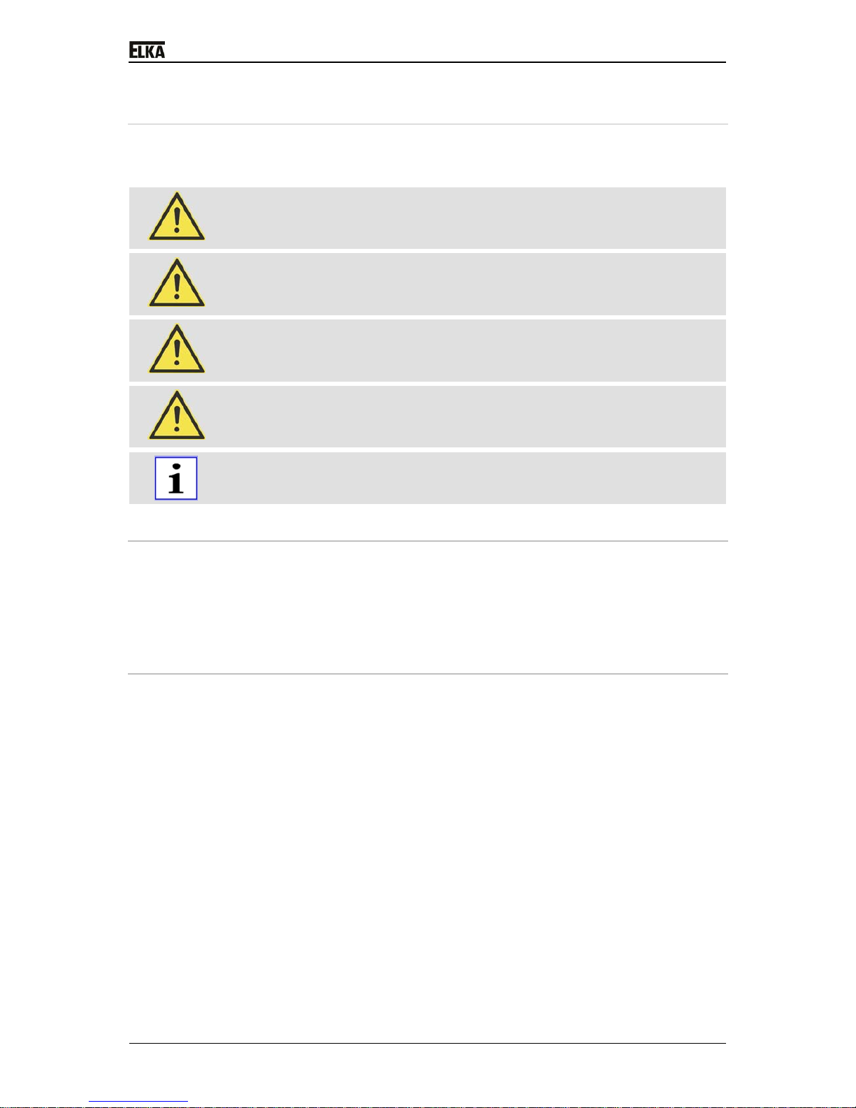
1.1.1 Symbol explanation
Remarks regarding the safety of persons and the gate opener itself are
marked by special symbols. These remarks have to be absolutely observed in
order to avoid accidents and material damage.
DANGER!
…points to an imminent dangerous situation, which can cause death or
serious injuries if it is not avoided.
WARNING!
…points to a potentially dangerous situation, which can cause death or
serious injuries if it is not avoided.
ATTENTION!
…points to a potentially dangerous situation, which can cause minor or
slight injuries if it is not avoided.
ATTENTION!
…points to a potentially dangerous situation, which can cause property
damage if it is not avoided.
REMARK!
Important notice for installation or functioning.
1.2 Copyright
The operating manual and the contained text, drawings, pictures, and other
depictions are protected by copyright. Reproduction of any kind – even in
extracts – as well as the utilization and/or communication of the content
without written release certificate are prohibited. Violators will be held liable for
damages. We reserve the right to make further claims.
1.3 Information regarding installation instruction
This document is to be used as installation instruction for partly completed
machinery (according to machinery directive 2006/42/EG, article 13, (2)).
Page 6

KOMET 200 - 60
0
2 Safety
2.1 General notes on safety
The valid regulations and standards have to be observed during installation
and operation, e.g. DIN EN 13241-1, DIN EN 12445, DIN EN 12453 etc.
Only the use of spare parts made by the original manufacturer is allowed. Do
not put a defective gate opener / barrier into operation.
After set-up (installation) every user of the equipment has to be instructed
about the operation and function of the gate opener / barrier.
2.2 Notes on safety for the operation
Children and not instructed persons are not allowed to operate the gate
system / barrier.
No persons, objects, or animals are allowed within the range of the gate
movement / barrier movement during opening or closing.
Never reach into moving parts of the gate operator, gate or barrier.
Drive through the gate system /barrier only after complete opening.
The gate system / barrier has to be secured depending on the type of usage,
corresponding to the valid standards and regulations (e.g. safety at the main
and secondary closing edges).
The safety devices have to be checked regularly for functioning according to
the standards and regulations, at least once a year.
2.3 Safety notes for the operation with radio remote control
The radio remote control should only be used, if the area of movement of the
gate / barrier is always completely visible by the operator and thus it is
assured, that no person, object, or animal is present within this range of
movement.
The radio remote control transmitters have to be carefully kept, so that an
unintentional use is impossible.
Radio remote controls should not be operated at radio-technical sensitive
locations, like airports or hospitals.
Interferences by other (properly operated) radio communication installations,
which are used within the same frequency range, cannot be ruled out.
2.4 Intended use
The operating safety is only guaranteed with the intended use of the gate
opener.
After the installation, the swing gate opener of this serve the purpose of traffic
flow control of vehicle paths (vehicle traffic only).
The controller MO 36 is a component part and controls the swing gate opener.
Any usage beyond this and/or any different application of the equipment
is prohibited and is considered as not according to regulations.
2.5 Danger, which could emanate from the site of operation
The swing gate opener operates with movable parts.
5
Page 7

KOMET 200 - 60
0
WARNING!
Rotating and/or linear movable components can cause serious injuries.
Do not reach into moving parts or handle any moving components during
operation.
Turn the appliance off before any maintenance work, repair work or other
work and secure it against unintentional restarting.
6
Page 8
KOMET 200 - 60
0
3 Transportation and storing
3.1 Transportation inspection
The shipment has to be inspected for transportation damage immediately after
receipt. In case of any damage record the type and extent on the delivery
receipt or refuse acceptance.
Inform ELKA-Torantriebe immediately in the event of damage.
In case the above points are not observed claims will be denied due to
insurance regulations.
3.2 Storing
The swing gate opener has to be stored as follows:
Do not expose the gate opener to aggressive substances.
Do not expose the gate opener to heat sources.
Storage temperature -20°C to +70°C.
7
Page 9
KOMET 200 - 60
0
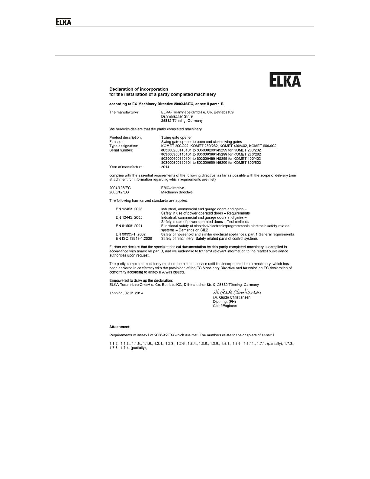
4 Declaration of incorporation
Drawing 1
8
Page 10

KOMET 200 - 60
0
4.1 Installation information for partly completed machinery
The partly completed machinery must not be put into service until the
final machinery into which it has to be incorporated has been declared
inconformity with the provisions of the machinery directive.
The safety functions of the controller comply with EN ISO 13849-1:2008
Kat.2PLc/d.
According to EC Directive 2006/42/EG the mains supply has to be equipped
with an all-pole circuit breaker.
WARNING!
Danger through voltage!
Danger of an electric shock.
Only certified electricians (VDE 0100) should connect the controller to the
mains supply.
According to DIN EN 12453, for an application with passenger traffic,
depending on the type of use and type of activation, suitable safety devices
have to be installed additionally, in order to provide the minimum level of
protection.
4.2 Declaration of conformity
After the installation an EG- declaration of conformity according to ECmachinery directive 2006/42/EG for the complete system has to be issued by
the person responsible for the integration (according to product standard DIN
EN 13241-1).
4.3 Name plate
The name plate of the swing gate opener is mounted inside the housing
(interior area close to the motor) or at the motor support.
9
Page 11

KOMET 200 - 60
0
5 Usage
The swing gate openers of series KOMET 200 - 600 are designed for gates
moving horizontally and having low wind resistance. For max. width and
weight of gate wing see table and diagram below.
When usage is different from the above samples, please contact your supplier.
1
0
Page 12
KOMET 200 - 60
0
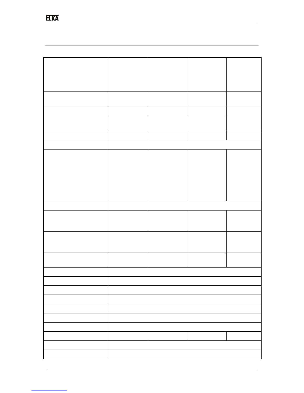
6 Technical Data
KOMET
200/202
one winged
gate/two
winged gate
KOMET
280/282
one winged
gate/two
winged gate
KOMET
400/402
one winged
gate/two
winged gate
KOMET
600/602
one winged
gate/two
winged gate
Maximum width of wing * 2.000mm /
wing
2.800mm /
wing
4.000mm /
wing
6.000mm /
wing
Maximum weight of wing 200kg 300kg 400kg 500kg
Maximum movement
(stroke)
370mm 500mm
Electromagnetic bolt no no yes yes
Emergency release from top and bottom
Running time (opening
angle 90°)
(each wing) **
stroke 280mm
= approx. 12s
stroke 350mm
= approx. 16s
stroke 300mm
= approx. 13s
stroke 350mm
= approx. 16s
stroke 320mm
= approx. 14s
stroke 350mm
= approx. 16s
stroke
440mm
= approx.
21s
stroke
500mm
= approx.
24s
Opening angle max. *** 120°
External limit stoppers at
opened positions required
****
yes no yes yes
External limit stoppers at
closed positions required
****
yes no yes yes
Limit stoppers at opened
and closed positions
optional yes no no
Power supply 230V, 50Hz
Operating voltage 24Vdc
Duty cycle 50%
Soft-Start and Soft-Stop yes, with ramp function
Controller, separately MO 36 (175x260x100mm, WxHxL)
Traffic light Module (optional)
Safety contact profile Separately for OPEN and CLOSE
Weight 19kg / 34kg 20kg / 35kg 19kg / 34kg 24kg / 44kg
Degree of protection IP 44
Temperature range -20°C up to +70°C
11
Page 13

KOMET 200 - 60
0
1
2
Maintenance The maintenance intervals must be decided individually as they
are dependent on the frequency of use. We recommend
maintenance at least once every 12 months.
Table1
* gates with low wind resistance
** depending on the installation dimensions (stroke) and the speed level
*** depending on the installation dimensions
**** A perfect fixation of the gate in position OPEN and CLOSED is only
possible with external stops!
Page 14
KOMET 200 - 60
0
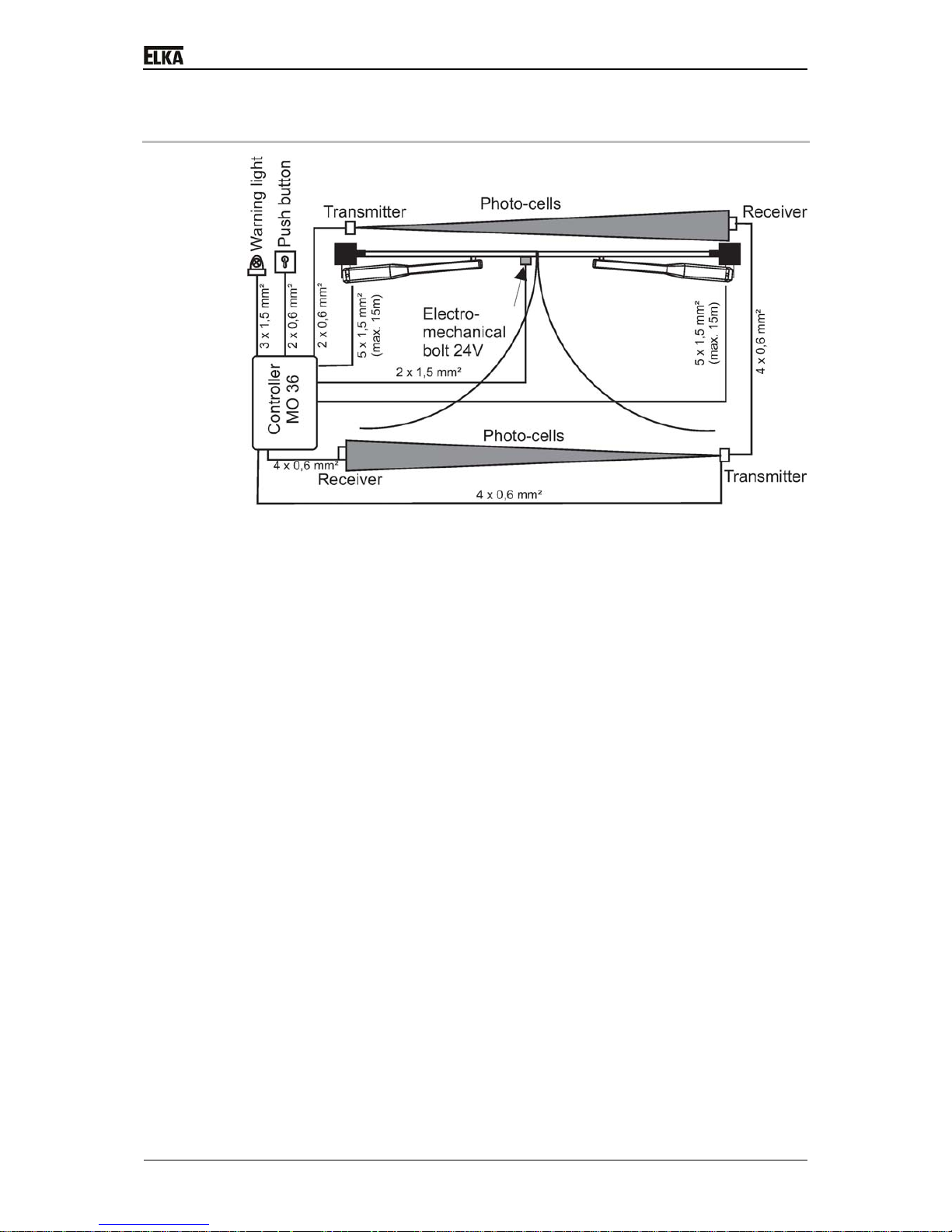
7 Installation example
Drawing 2
1
3
Page 15

KOMET 200 - 60
0
8 Installation
8.1 Installation dimensions (pivot point)
All measurements are quoted in millimetre.
The opener KOMET is for usage left and right.
Drawing 3
14
Page 16

KOMET 200 - 60
0
KOMET 200/280/400
C = approx. 100mm
D = approx. 80mm
E = 1010mm
Drawing4
KOMET 600
C = approx. 100mm
D = approx. 120mm
E = 1245mm
Drawing 5
1
5
Page 17

KOMET 200 - 60
0
Mounting dimensions – Opening angles:
Table of opening angels KOMET 200
depending on measurements A and
B.
Opening angle A / B * A / B * A / B * A / B * A / B *
90° 140 / 140 150 /150 160 / 160 170 / 170 180 / 180
95° 140 / 130 150 / 140 160 / 150 170 / 160 180 /170
100° 150 / 130 160 / 140 170 / 150 180 / 160 -
105° 160 / 130 170 / 140 180 / 150 - -
110° 170 / 130 180 / 140 - - -
115° 180 / 130 - - - -
120° 180 / 120 - - - -
Table 2 - (*All measurements are quoted in millimetre.)
Table of opening angels KOMET 280depending on measurements A and
B.
Opening angle A / B * A / B * A / B * A / B *
90° 150 / 150 160 /160 170 / 170 180 / 180
95° 150 / 140 160 / 150 170 / 160 180 / 170
100° 160 / 140 170 / 150 180 / 160
105° 160 / 130 170 / 140 180 / 150 -
110° 170 / 130 180 / 140 - -
115° 180 / 130 - - -
120° 180 / 120 - - -
Table 3 - (*All measurements are quoted in millimetre.)
Table of opening angels KOMET 400depending on measurements A and
B.
Opening angle A / B * A / B * A / B *
90° 160 / 160 170 /170 180 / 180
95° 160 / 150 170 / 160 180 / 170
100° 170 / 150 180 / 160 -
105° 170 / 140 180 / 150 -
110° 180 / 140 - -
115° 180 / 130 - -
120° 180 / 120 - -
Table 4 - (*All measurements are quoted in millimetre.)
1
6
Page 18

KOMET 200 - 60
0
Table of opening angels KOMET 600depending on measurements A and
B.
Opening angle A / B * A / B *
90° 225 / 225 240 / 240
95° 225 / 210 240 / 225
100° 225 / 195 240 / 210
105° 225 / 180 240 / 195
110° 240 / 180 -
115° 240 / 165 -
120° 240 / 150 -
Table 5 - (*All measurements are quoted in millimetre.)
The measurement E for KOMET 200 / KOMET 280 / KOMET 400 is
1,010mm each, for the KOMET 600 it is 1,245mm. To exceed these
measurements may result in a disruption of operation. To go below
these measurements, reduces the opening angle.
Please strictly observe the approved measurements. This is necessary
for an optimal operation. In case these measurements cannot be
observed, please send us your dimensional drawing for checking.
External stops for gate OPEN and gate CLOSED are mandatory for the
gate openers KOMET200, KOMET 400, and KOMET 600.
8.2 Installation dimensions (elevation)
Drawing6
1 Mounting support P
2 Mounting support T 24mm higher than mounting support P
Please make sure, that the gate wings can be moved easily and that the axis
of rotation is in a completely vertical position. Check that there is enough room
for the opener behind the opened gate.
1
7
Page 19

KOMET 200 - 60
0
WARNING! The controller needs to be disconnected while welding is
performed on the gate.
8.3 Installation at the gate and gate post
Drawing 7
1 Mounting support P
2 Mounting support P with base plate (on side)
1. Secure the mounting support P on the gatepost at a height above the
ground in which the mounting support T can also be secured properly on
the gate. Welding seams have to be matched to the metal sheet thickness
of the mounting support P.
2. Close the gate so that it presses against the end stopper. Determine the
connection point of the mounting support T at the gate. Make sure that the
distance to the gate is sufficient, so that the gate opener does not touch
the gate later during movement. Using a water level determine the correct
height. Keep the necessary distance “E“ between the mounting supports P
and T.
Drawing 8
1 Mounting support T
2 Mounting support T with base plate (on side)
3. For steel gates: connect the mounting support T to the gate using tack
welding. If neccessary weld the mounting support to a reinforcement plate
(on site) and connect the reinforcement plate to the gate using tack
welding. For other gates: weld the mounting support to a support plate (on
site, approx.120x80x15mm) and connect the support plate to the gate (e.g.
using screws).
1
8
Page 20

KOMET 200 - 60
0
Drawing 9
4. Fit the gate opener with the joint bolts into the mounting supports P and T
at gatepost and gate. Release the opener as described under 9. page 22
Now open and close the
gate manually. Check if the gate can be moved
the complete distance between the end positions easily. Remove the gate
opener. Complete the final connection of the mounting supports P and T.
Grease the drill hole of the mounting support P slightly. Fit the gate opener
to the gate again. Tighten the screw at the gatepost, but not too tight.
Secure the fixing nut using the stop nut. Connect the joint bolt (gate) to the
mounting support T using the Screw.
5. All electrical connections should be according to the description for the MO
36control box 10 - Controller MO 36.
6.
Now close the gate and engage the gate opener. Continue with 10.3 Programming MO36.).
7.
Install now the periphery equipment like key switches, photo-cells etc. and
lay the electrical cabling according to the installation example on page 13.
Make sure that the cable cannot be
tensed or damaged by the gate or the
moving gate opener.
8.4 Adjusting of the internal stops (KOMET 200 and 280)
If external stops are installed, make sure that the gate wing pushes
against the external stop with slight force only.
1. Disengage the emergency release as described under 9 - Emergency
release .
2.
Move the gate wing/s to an opening angle of approx. 45°.
3. Reengage the emergency release.
4. Loosen the screw at the mounting support T.
5. Lift the narrow end of the gate opener out of the mounting support T.
6. Three counter sunk screws at the end of the arm and another three
between the aluminium arm and the push rod can now be seen from below
(these are the internal stops). Loosen these six screws. Move the internal
stops closer to the driver (joint bolt) using the socket wrench. Tighten the
screws slightly, so that the internal stops cannot shift accidentally on their
own.
1
9
Page 21

KOMET 200 - 60
0
Drawing 10
1 Internal stops
7. Replace and refit the opener to the mounting support T. Now connect the
opener/s to the terminals of the controller MO 36. Connect the main wing
to the terminal FAHR and the pedestrian wing to the terminal GEH. For
one winged gates connect the wing to the terminal FAHR.
8. Connect to the mains.
ATTENTION! During the next steps the gate wing will be moved electrically.
Make sure the range of movement is free from obstacles. During learning the
safety devices can react differently from the normal operation.
9. Press the button LERN on the controller for approx. 2 seconds. The
display shows p1.Press the button LERN again. The display now shows
1f.
10. Now select the number of gate wings. Push button BT until it displays 2f.
Confirm the displayed 2f (for two wings) with the button LERN. The
display shows ha (manual operation).
11. Now you can move each gate wing separately into the end positions in
slow mode (dead man´s function). The main wing moves into direction
OPEN only as long as button BT is pressed. When button BT is pushed
again, the wing moves into direction CLOSED. The pedestrian wing moves
into direction OPEN only as long as button BTG is pressed. When button
BTG is pushed again, the wing moves into direction CLOSED.
12. Now move the main wing with button BT into the end postitions OPEN and
CLOSED. Now move the pedestrian wing with button BTG into the end
positions OPEN and CLOSED. The internal end stops are now adjusted
but not fixed.
13. Move the gate wings with button BT and BTG into position „half OPEN“.
ATTENTION! Do not give any further commands to the controller now.
14. Remove the plug from the 5-pin connection FAHR and GEH.
15. Loosen the screw at the mounting support T. Lift the narrow end of the
gate opener out of the mounting support T.
16. The three counter sunk screws from the internal stop must be tightened
by allen key.
17. Replace and refit the opener to the mounting support T.
18. Now connect the gate opener to the controller MO36.
2
0
Page 22

KOMET 200 - 60
0
21
ATTENTION! The gate moves automatically during the next installation step.
19. During the following step the controller learns the running distance of the
(one or two) gate wings. Push the button LERN. The controller sends the
wing/wings into direction OPEN to the end stop and then into direction
CLOSED to the end stop. The display shows P2.
20. The gate is now in position CLOSED. Should the gate now be in position
OPEN, the wires 4 and 5 of the motor connection cable at the 5-pin
connection have to be switched. Then repeat by pressing button BTG
once (1x - display p1) and pressing button LERN three times (3x - display
1f, ha and au).
21. Push the button BT until pp is displayed. Confirm with button LERN.
22. Continue with paragraph - Programming MO36.
Shall the end position of one or both gate openers be changed, proceed us
described under 8.4 - Adjusting of the internal stops (KOMET 200 and 280).
You may also loosen the end stops separately and thus adjust them.
Page 23

KOMET 200 - 60
0
9 Emergency release
9.1 Emergency releasing
Depending on the accessibility remove either the plastic cap on top or the one
at the bottom of the gate opener. Place the wrench into the opening until it
engages into the locking device (hexagon socket).
Drawing 11
1 release
2 engage
When using the top emergency release, turn the wrench approx. ½ turn
anticlockwise. When using the bottom emergency release, turn the wrench
approx. ½ turn clockwise. The gate wing can now be moved freely.
The display in the controller shows ef (EF = message from the controller MO
36 that at least one opener is disengaged).
9.2 Engaging of emergency release
Insert the wrench into the emergency release. Turn the wrench approx. ½ turn
clockwise. The overcoming of the dead point must be clearly noticeable (when
engaging the emergency release at the bottom, turn the wrench
anticlockwise). In case the wrench can only be moved slightly out of its original
position, move the gate wing until the teeth of the gear interconnect and the
wrench can be moved approx. ½ turn.
When the emergency release is correctly engaged, the display on the
controller stops showing ef.
At the next use of BT the gate wing moves into position OPEN for
synchronizing. At the following use of BT the opener moves in normal mode.
2
2
Page 24

KOMET 200 - 60
0
10 Controller MO 36
10.1 Electrical installation
The leads must be inserted from below. For gates with two wings a minimum
cross section [mm²] of the lead is necessary, which is determined by the
length of the lead between the 2.opener and the controller.
Cross sections selected too small will have adverse effect on the motor
performance.
For the gate openers (with controller MO 36) the following lead dimensions are
required:
Cross section: 5 x 1,5mm² up to 15m distance
Cross section: 5 x 2,5mm² up to 20m distance
Power supply for the controller: 230Vac, 50Hz, single Phase
Connection: By fixed wiring and main switch (on site) or flexible wiring with
cable stress relief device according to the European standards.
The provided motor cable is only suitable for the short way to the connection
box; a mechanical protection should be used where applicable. For the longer
connection distance between gate opener and controller please use a suitable
cable. Here also use a mechanical protection (conduit) if applicable.
REMARK! For the connection of the motor lead to the controller MO 36 use
solely leads with flexible conductors, like e.g. ÖLFLEX ROBUST 210.
Cable configuration:
Mark Contacts on the MO 36
1 GND
2 IMP
3 I+
4 M-
5 M+
Table 6
2
3
Page 25

KOMET 200 - 60
0
10.2 Connections
10.2.1 Connection plan of the controller MO36
Each safety contact strip terminal which is not used has to be linked to an
8.2kΩ resistor.
Each photo-cell and stop terminal which is not used has to be linked to a
j
umper.
Drawing 12
24
Page 26

KOMET 200 - 60
0
10.2.2 Input terminals
Input Description Connection Function
BT n.o. contact 1 pin Push button (serial
switching)
BTG n.o. contact 1 pin Push button for pedestrian
opening
BA n.o. contact 1 pin Push button OPEN
BZ n.o. contact 1 pin Push button CLOSE
Ground - 1 pin Mutual ground BT, BTG, BA
and BZ
BS n.c. contact 1 pin Push button STOP
Ground - 1 pin Ground for STOP
LSA
LSI
Each max. 6 photocells with n.c. contact
and terminating
resistor 1kΩ
2 pin Photo-cells for installation
outside (LSA) and inside
(LSI)
(according to EN954-1
category 2)
Ground - 1 pin Mutual ground LSA and LSI
SLA
SLZ
Safety contact profile:
resistor detection n.c.
contact with 8.2kΩ
resistor (serial or
parallel with n.o.
contact with 8.2 kΩ)
2 pin Integrated detectors with
testing function (according
to EN954-1 category 2) for
safety contact profile for
gate OPEN (SLA) and
CLOSE (SLZ)
Ground - 1 pin Mutual ground SLA and SLZ
IMPg pulser See motor Pulser for pedestrian wing
IMPf See motor Pulser for main wing
SU Plug socket Connection for timer module
ASU2
Funk Plug socket
for receiver
EKX1OF or
receiver
with
decoder
Integrated receiver for BT,
BTG and MULTI
Netz
(L1, N
and
PE)
- 3 pin Power supply
230Vac – L1, N and PE
Table7
10.2.3 Buttons on the controller
Mark Function
2
5
Page 27

KOMET 200 - 60
0
BT Same function as external button BT
BTG Same function as external button BTG
LERN Starting the learning mode
Table 8
10.2.4 LEDs on the controller
Mark Colour Function Desired value
Vp Yellow Lights when connected to main
power
ON
SLA Red Lights when safety contact
profile SLA active
OFF
SLZ Red Lights when safety contact
profile SLZ active
OFF
BT Green Lights when the contact is closed OFF, when
pushing button =
ON
BTG Green Lights when the contact is closed OFF, when
pushing button =
ON
BA Green Lights when the contact is closed OFF, when
pushing button =
ON
BZ Green Lights when the contact is closed OFF, when
pushing button =
ON
BS Green Lights when the contact BS is
closed
ON
LSA Green Lights when LSA is interrupted OFF
LSI Green Lights when LSI is interrupted OFF
Display Red 2 x 7-segment-display OFF
Table 9
2
6
Page 28

KOMET 200 - 60
0
10.2.5 Output terminals
Output Connection Corresponds to:
Motor
pedestrian
wing
and IMP
g
5 pin Connection for 24Vdc motor and pulser for
the pedestrian wing
Motor main
wing
and IMP
f
5 pin Connection for 24Vdc Motor and pulser for
the main wing or for one-winged gates
SCHLOSS 3 pin Connection for electromagnetic bolt or
magnetic lock with 24Vdc (max. 1A)
WARN 2 pin Potential-free contact for warning light
230Vac /max. 60W
MULTI 2 pin Potential-free contact for multi-functional
relays(230Vac / max. 60W)
Uext 3 pin 24Vdc and 12Vdc, mutual ground terminal,
stabilised direct voltage, together max.
300mA, ground terminal is connected with
controller ground
LS-TEST 1 pin 24Vdc for photo-cell transmitter
PE 1 pin Earth
AMPEL 2 pin Socket for traffic light module AMO34A red /
green
Table 10
10.3 Programming MO36
For programming and to set operating parameters, use the two-digit 7segment display and the buttons BT, BTG and LERN.
At least the following sequences have to be learned as basic
configuration:
P1 - Learning of running distance
P2 - Selecting of force and speed
PC - Pressure relief of electromechanical bolt (mandatory when
using optional internal blocking)
10.3.1 Learning sequence
During normal operation the display is off. The learning sequence is
activated by pushing the button LERN for approx. 2s. The display shows
P1. The sequence 1 is pre-set. With the button BT you can move on to the
next sequence P2, P3 etc. With the button BTG you can move back to the
last sequence. When the required sequence is displayed it has to be activated
with the button LERN.
Sequence Function
p1
Selection one wing / two wings
2
7
Page 29

KOMET 200 - 60
0
Adjusting of end stops
Learning of safety contact profiles and photo-cells
connected
Learning of running distance
p2
Adjusting of force and speed
p3
Adjusting of time lag of the pedestrian wing during closing
p4
Adjusting of time lag of main wing during opening
p5
Learning of radio remote control codes for BT, BTG and
MULTI
Deleting of radio remote control codes for BT, BTGand
MULTI
p6
Automatic closure for complete opening (for both wings)
activating / deactivating
change stay-open time
p7
Automatic closure for pedestrian wing
activating / deactivating
change stay-open time
p8
Selecting of warning prior to opening and closing
p9
Selecting of photo-cell function
pa
Activating / deactivating photo-cell testing
pb
Activating / deactivating lockage function for photo-cells
pc
Selecting pressure relief of electromagnetic bolt
pd
Selecting wind blast suppression
pe
Selecting mode of multi-functional relay
pf
Return to original settings
pp
Saving of data and returning to regular mode
Table 11
10.3.1.1 Sequence P1: Learning of the running distance
When sequence P1 has been activated, it has to be selected first between
gates with one (1F) or with two (2F) wings using button BT. Then confirm the
selection with button LERN.
Display Effect / Function
1f
To operate gates with one wing
2f
To operate gates with two wings
Table 12
Then ha is displayed. The gate wings now can be operated by dead man’s
motion using buttons BT or BTG to adjust the internal mechanical end. BT
is used for the main wing and BTG for the pedestrian wing. The first
direction is always OPEN.
2
8
Page 30

KOMET 200 - 60
0
ATTENTION! During learning the safety devices may act different from the
regular operation. Please ensure that no people are in the danger area during
learning.
After adjusting the end stoppers, push the button LERN to continue: The
controller tests the safety contact strips and the photo-cells. It learns the type
of the safety contact strips (8.2 kΩ) and the number of connected photo-cells.
Only when this photo-cell testing was successful, additional photo-cell tests
can be carried out during future operation.
Gates with
one wing:
During learning of the running distance the wing opens first
and then closes.
Gates with
two wings:
During learning of the running distance the pedestrian wing
opens, the main wing opens, the main wing closes and
pedestrian wing closes.
In both cases the wings move until they hit the stoppers at the closed position.
During the learning of the running distance the pressure relief of the
electromechanical bolt is not in function. The electromechanical bolt is being
activated during each wing movement. After the learning of the running
distance, returning to the main sequence follows automatically.
Remark: After adjustment of the end stoppers, the wings should not be in
either end position but at least 50cm before. The first movement is into
direction open.
10.3.1.2 Sequence P2: Adjusting of force and speed
The force and speed can be adjusted for each wing separately, and for
opening and closing separately.
When sequence P2 is activated by button LERN an additional selection menu
for force and speed opens. With button BT you may move to different
points of the selection menu.
Subsequence Function
f1
Force for opening of main wing (2-winged gates) / the wing
(1-winged gates)
f2
Force for closing of main wing (2-winged gates) / the wing
(1-winged gates)
f3
Force for opening of pedestrian wing. No function with 1winged gates.
f4
Force for closing of pedestrian wing. No function with 1winged gates.
s1
Speed for opening of main wing (2-winged gates) / the wing
(1-winged gates)
s2
Speed for closing of main wing (2-winged gates) / the wing
(1-winged gates)
s3
Speed for opening of pedestrian wing. No function with 1winged gates.
s4
Speed for closing of pedestrian wing. No function with 1winged gates.
2
9
Page 31

KOMET 200 - 60
0
13
With the button LERN the selected point can be activated. The present value
for force (F = force) or speed (S = speed) is displayed. Possible values are
01 (for minimum force) up to 99 (for maximum force) or 01 (for minimum
speed) up to 08 (for maximum speed). With button LERN the values may be
increased, with the button BTG they can be decreased. Return to the learning
sequence using button LERN.
ATTENTION! The maximum force (F1 - F4) has to be adjusted according to
the relevant gate opener using the learning sequence. If a force higher than
shown below is adjusted, the motor will not be able to reverse on obstacle.
Swing gate opener Adjustment range
KOMET 200/202 F1 – F4 = max. 35
KOMET 280/282 F1 – F4 = max. 35
KOMET 400/402 F1 – F4 = max. 45
KOMET 600/602 F1 – F4 = max. 55
Table 14
10.3.1.3 Sequence P3: Time lag of the pedestrian wing (closing)
When sequence P3 is activated by button LERN, the present value for the
time lag of the pedestrian wing during closing is displayed. Possible values are
00 (for 0s) up to 09 (for 9s). The value can be increased using button BT
and decreased using button BTG. Return to the learning sequence using
button LERN.
Remark: When a time lag is selected for gates with one wing, it will not be in
effect.
10.3.1.4 Sequence P4: Time lag of the main wing (opening)
When sequence P4 is activated by button LERN, the present value for the
time lag of the pedestrian wing during closing is displayed. Possible values are
00 (for 0s) up to 09 (for 9s). The value can be increased using button BT
and decreased using button BTG. Return to the learning sequence using
button LERN.
Remark: When a time lag is selected for gates with one wing, it will not be in
effect.
10.3.1.5 Sequence P5: Learning and deleting of code for radio remote control
To learn a code the transmitter has to be operated. The code will then be
stored. When sequence P5 is activated with the button LERN, an additional
selection menu is displayed for selecting the code. Move to the next point
using button BT.
Sub-sequence Function
c1
Radio remote control code for BT can be learned or deleted
c2
Radio remote control code for BTG can be learned or
deleted
3
0
Page 32

KOMET 200 - 60
0
c3
Radio remote control code for MULTI can be learned or
deleted
Next Return to main sequence
Table 15
Sub-sequence is activated with button LERN. The display shows:
Display Corresponds to:
--
The selected radio remote control code is deleted and
another can be learned.
xx
The selected radio remote control code is already stored and
can be overwritten or deleted.
Table 16
To erase the radio remote control code, press and hold the button BT and
additionally push the button LERN. The radio remote control code is erased.
Return to the subsequence follows automatically. If only the button LERN is
pushed, then return to the subsequence follows immediately without erasing
the code.
Radio remote control signal: Receiving of a learned radio remote control
signal is displayed through lighting of the right display dot.
31
Page 33

KOMET 200 - 60
0
10.3.1.6 Sequence P6: Automatic closure for complete opening
When sequence P6 is activated by button LERN, the present value for stayopen time for complete opening is displayed. Possible values are -- (not
activated), 01 up to 299 (for 1s -299s). The value can be increased using
button BT and decreased using button BTG. The decimal dots of the
display are each equal to 100 (one lit dot = 100 / two lit dots = 200).
Display(example) Corresponds to:
--
Automatic closure is deactivated.
23
Automatic closure is activated. Stay-open time 23
seconds.
2.3
Automatic closure is activated. Stay-open time 123
seconds.
2.3.
Automatic closure is activated. Stay-open time 223
seconds.
Table 17
Return to the learning sequence using button LERN.
When using automatic closure both wings close automatically after the learned
stay-open time has elapsed. The stay-open time starts elapsing when the last
wing has reached the position OPEN.
When contact BS is opened, the automatic closure function is blocked.
When the stay-open time has elapsed and the safety contact profile for
direction CLOSE (SLZ) is currently activated, the gate remains open. The
elapsed stay-open time will not be repeated. When the SLZ is not
activated anymore and the stay-open time has elapsed, the warning time
prior to closing starts.
When the automatic closure function is blocked it will be reactivated with a
new signal (BA or BT).
When the lockage function for the photo-cells is activated, the automatic
closure function is blocked, as long as an obstacle is present between the
photo-cells (see sequence PB).
When the gate hits an obstacle during closing and reversing is activated
through SLZ, the gate opens. When automatic closure is activated and the
obstacle is not removed, the gate will try to close twice. After hitting the
obstacle for the second time the gate will reverse for a short distance and
stop.- The counting will be erased when using BT, BA, or BZ.
3
2
Page 34

KOMET 200 - 60
0
10.3.1.7 Sequence P7: Automatic closure for pedestrian wing
When sequence P7 is activated by button LERN, the present value for stayopen time for the pedestrian wing is displayed. Possible values are -- (not
activated), 01 up to 299 (for1s - 299s). The value can be increased using
button BT and decreased using button BTG. The decimal dots of the
display are each equal to 100 (one lit dot = 100 / two lit dots =200).
Display(example) Corresponds to:
--
Automatic closure is deactivated.
23
Automatic closure is activated. Stay-open time 23
seconds.
2.3
Automatic closure is activated. Stay-open time 123
seconds.
2.3.
Automatic closure is activated. Stay-open time 223
seconds.
Table 18
Return to learning sequence using button LERN.
When using automatic closure the pedestrian wing closes automatically after
the learned stay-open time has elapsed. The stay-open time starts elapsing
when the wing has reached the position OPEN.
When contact BS is opened, the automatic closure function is blocked.
When the stay-open time has elapsed and the safety contact profile for
direction CLOSE (SLZ) is currently activated, the gate remains open. The
elapsed stay-open time will not be repeated. When the SLZ is not
activated anymore and the stay open time has elapsed, the warning time
prior to closing starts.
When the automatic closure function is blocked it will be reactivated with a
new signal (BA or BT).
When the lockage function for the photo-cells is activated, the automatic
closure function is blocked, as long as an obstacle is present between the
photo-cells (see sequence PB).
When the gate hits an obstacle during closing and reversing is activated
through SLZ, the gate opens. When automatic closure is activated and the
obstacle is not removed, the gate will try to close twice. After hitting the
obstacle for the second time the gate will reverse for a short distance and
stop. The counting will be erased when using BT, BA, or BZ.
3
3
Page 35

KOMET 200 - 60
0
10.3.1.8 Sequence P8: Warning prior to opening and closing
When sequence P8 is activated by button LERN, the present value for
warning time (opening and closing) is displayed. With the button BT the value
can be selected (see table).Return to the learning sequence using button
LERN. The warning light is only active, when a gate wing is moving and during
warning prior to opening and closing.
Display Warning time before
opening
Warning time before
closing
oo
No warning time No warning time
o4
No warning time 4 seconds warning time
4o
4 seconds warning time No warning time
44
4 seconds warning time 4 seconds warning time
Table 19
10.3.1.9 Sequence P9: Photo-cell function
When sequence P9 is activated by button LERN, the present selection for the
photo-cell function is displayed. With the button BT the value can be selected
(see table). Return to the learning sequence using button LERN.
Drawing 13
Function Photocell Gate not
moving
Gate opens Gate closes
l1
LSI Remains not
moving
Stops when
interrupted,
opens when
free again
Stops when
interrupted,
opens when
free again
LSA Remains not
moving
Stops when
interrupted,
opens when
free again
Stops when
interrupted,
opens when
free again
34
Page 36

KOMET 200 - 60
0
l2
LSI Remains not
moving
Stops when
interrupted,
opens when
free again
Stops when
interrupted,
closes when
free again
LSA Remains not
moving
Stops when
interrupted,
opens when
free again
Stops when
interrupted,
closes when
free again
l3
LSI Only closing
allowed
Stops when
interrupted,
opens when
free again
No effect
LSA Only opening
allowed
No effect Stops and
opens
immediately
Table 20
3
5
Page 37

KOMET 200 - 60
0
10.3.1.10 Sequence PA: Photo-cell testing
Prior to every gate movement a photocell test may be performed. The test
consists of two phases. During the first phase the supply of the transmitters is
switched off. The controller expects within the next 2.5 s that the receiver
reports an obstacle. During the second phase the supply of the transmitter is
switched on again. The controller expects the receiver to report no obstacle
any more. Only after this procedure the gate can move. If an error occurs in
the first phase, the photocell (receiver) is damaged. The gate will not move.
An error message is given through the display. If an error occurs in the second
phase, the controller interprets this as a real obstacle. The gate will not move.
No error message is given. You may connect and test each (LSI and LSA)
maximum 6 pairs of photocells with the controller MO 36. Therefore add all
n.c. relay contacts of the receivers in serial. Parallel to each relay contact you
must add a 1kOhm resistor (resistors are needed only when photocell test is
used).
Drawing 14
ATTENTION! The MO 36 must learn how many photocells are connected to it.
Activate the test by setting PA = ON and run the learning of the running
distance P1.
After this please check every single photocell for proper function.
REMARK: When a faulty photo-cell is detected during photo-cell testing or
when an obstacle is present within the photo-cell, the gate can be opened and
closed in emergency mode (dead man’s function).
When sequence PA is activated by button LERN, the present selection for
the photo-cell testing is displayed. With the button BT the value can be
selected (see table).Return to the learning sequence using button LERN.
Display Corresponds to:
xf
Photo-cell testing deactivated
xn
Photo-cells, which have past the LS-Test during sequence
P1, will execute photo-cell testing also in regular mode.
3
6
Page 38

KOMET 200 - 60
0
Table 21
10.3.1.11 Sequence PB: Lockage function for the photo-cells
Drawing 15
When using photo-cells in connection with the automatic closure for both
wings, a lockage function is possible. To activate this function use the learning
sequence.
The lockage function is only activated when the gate is opened.
When the gate reaches the end position OPEN, the lockage function is
initialised. This means: when a vehicle passes through the gate from the
outside, a signal from LSA (photo-cell outside) blocks the automatic
closure function. Only the signal from LSI (photo-cell inside) removes the
blocking and starts the stay-open time.
When a vehicle passes through the gate from the inside, a signal from LSI
blocks the automatic closure function. Only the signal from LSA removes
the blocking and starts the stay-open time.
When sequence PB is activated by button LERN, the present selection is
displayed. With the button BT the value can be selected (see table).Return to
the learning sequence using button LERN.
Display Corresponds to:
xf
Lockage function is deactivated.
xn
Lockage function is activated (only working when automatic
closure is selected.) When the photo-cell is interrupted,
closing of the gate wing / wings is only possible, when the
vehicle / person has passed both (LSA and LSI) photo-cells.
Table 22
10.3.1.12 Sequence PC: Pressure relief of electromechanical bolt
When sequence PC is activated by button LERN, the present selection is
displayed. With the button BT the value can be selected (see table). Return to
the learning sequence using button LERN.
3
7
Page 39

KOMET 200 - 60
0
Display Corresponds to:
S1
Pressure relief for electromagnetic bolt is deactivated.
S2
The gate wing pushes slowly (500ms min., but 1000ms max.)
against the end stopper until the selected force is reached.
S3
The gate wing pushes slowly (500ms min., but 2000ms max.)
against the end stopper until the selected force is reached.
S4
The gate wing pushes slowly (500ms min., but 90s max.)
against the end stopper until the selected force is reached.
Table 23
10.3.1.13 Sequence PD: Wind blast suppression
It can be chosen to either reverse on obstacle immediately, or to reverse after
a preset time. When setting a time, a short wind blast or an oscillating gate
wing do not result in a stop (and reversal).
ATTENTION! Only use the wind blast suppression, when additional
safety devices like photo-cells and safety contact profiles are installed at
the gate.
When sequence PD is activated by button LERN, the present selection is
displayed. With the button BT the value can be selected (see table). Return to
the learning sequence using button LERN.
Display Corresponds to:
u-
No wind blast suppression. The controller immediately reacts
on obstacle/wind blast.
u1 bis u9 The wind blast suppression equals 1s (for U1) up to 9s (for
U9). The controller reacts on obstacle / wind blast only after
the selected time1s (for U1) up to 9s (for U9).
Table 24
10.3.1.14 Sequence PE: Multi-functional relay
The multi-functional relay on the controller is suitable for four different modes.
During learning function the relay is inactive.
When sequence PE is activated by button LERN, the present selection is
displayed. With the button BT the value can be selected (see table).
Return to the learning sequence using button LERN.
Display Corresponds to:
r1
Push button mode: The relay is active as long as the
controller receives the radio remote control code MULTI.
r2
Toggle mode: The relay alternates between active and
deactive with each radio remote control code MULTI.
r3
Light pulse mode: The relay is active for 1 second, when BT,
FunkBT, BTG, Funk BTG, BA or BZ are pushed.
r4
3-minute light: The relay is active for 180 seconds, when BT,
FunkBT, BTG, Funk BTG, BA or BZ are pushed.
Table 25
3
8
Page 40

KOMET 200 - 60
0
10.3.1.15 Sequence PF: Return to original settings
When sequence PF is activated by button LERN, re is displayed. To return
to original settings, press and hold button BT and push button LERN.
When only button LERN ispushed, you return to learning sequence without
changing any values. After returning to original settings, the running distance
has to be relearned.
3
9
Page 41

KOMET 200 - 60
0
10.4 Safety contact profiles for gate open (SLA) and close
(SLZ)
Gates with two wings: When a safety contact profile is activated, both motors
react.
The controller has two integrated detectors with testing function (according to
EN954-1 category 2 for safety contact profiles with 8.2kOhm resistor) for gate
OPEN and CLOSE. The status of the safety contact profiles is displayed by
red LEDs (SLA and SLZ). When the safety contact profile is activated, the
matching LED lights.
Direction of
movement
Function of SLA Function of SLZ
From stop to open Only possible in
emergency mode
-
From stop to
closing
- Only possible in
emergency mode
Opening Stop and movement for a
short distance into
direction closed
-
Closing - Stop and re-opening
Table 26
Automatic closure: When the gate hits an obstacle during closing and
reversing is activated through SLZ, the gate opens. When automatic closure is
activated and the obstacle is not removed, the gate will try to close twice. After
hitting the obstacle for the second time the gate will reverse for a short
distance and stop.- The counting will be erased when using BT, BA, or BZ.
The connection of the n.o. contact with 8.2kΩ ±5% resistor (parallel) or the n.c.
contact with 8.2kΩ ±5% resistor (serial) is possible. In case no safety contact
profiles are connected, an 8.2kΩ ±5% resistor has to be connected. When
using more than one safety contact profile, they can be connected in
sequence (see drawing below).
Drawing 16
4
0
Page 42

KOMET 200 - 60
0
10.5 Additional modules
10.5.1 Timer module ASU2 (optional)
The timer module can be plugged onto the controller. Function: When the
timer has reached the set time for open, it sends an OPEN command to the
controller. The gate cannot be closed as long as the timer is activated. After
the open time has elapsed, the timer sends a CLOSE command to the
controller. Note: When the timer sends the CLOSE command, the gate is
closed immediately, even when automatic closure is activated.
10.5.2 Traffic light module AMO34A (optional)
Red and/or green traffic lights can be connected to the traffic light module.
Drawing 17
Gate position Red traffic light Green traffic light
Gate is
completely
open
Off On
Gate is not
open (it is
moving,
partially open,
orclosed)
On Off
Table 27
41
Page 43

KOMET 200 - 60
0
10.6 Power failure
After power failure or disconnecting from mains the position of the wing/wings
is unknown to the controller. The controller first works in a starting mode. The
wings are moving slowly. A pressure relief of electromagnetic bolt occurs
before every movement. The wings close one after the other. When stopping
at the end position (closed), the controller recognises this position. The
controller continues in its regular mode. Note: Emergency mode is possible
during the starting mode.
10.7 Fault diagnosis
An error is shown on the display as a code, when detected by the controller.
The following errors are recognised and displayed.
Display Error
e1
Photo-cell testing LSI failed.
e2
Photo-cell testing LSA failed.
e3
Testing safety contact profile SLA failed.
e4
Testing safety contact profile SLZ failed.
e5
Running distance exceeded (gate was stopped). Check end
stoppers and re-learn the running distance.
e6
The power supply limit for the external equipment 12V has
been reached. The power source load is too high. The
controller is blocked.
e7
The power supply limit for the external equipment 24V has
been reached. The power source load is too high. The
controller is blocked.
e8
The memory data has been lost / is faulty. The controller has
to be relearned.
e9
Error in storing of data on memory. Controller is faulty. Return
for repairs.
ea
Error in the redundant detection of BS. Controller is faulty.
Return for repairs.
eb
The controller detects one of the motor relays is faulty. Return
for repairs.
ec
Measuring amplifier faulty. Return for repairs.
ed
The main wing pulser is faulty. Check the wiring between the
opener and controller.
ee
The pedestrian wing pulser is faulty. Check the wiring
between the opener and controller.
ef
Power supply Uext has a short cut. OR At least one wing is
released. Check the emergency release.
Table 28
4
2
Page 44

KOMET 200 - 60
0
10.8 Emergency mode
In case a safety device (LSA, LSI, SLA or SLZ) is faulty, emergency mode is
possible. After a warning time of 10 seconds, the gate can be moved in an
emergency mode by using BA or BZ (dead man’s function). During the
warning time as well as during the emergency mode the warning light is
flashing. Emergency mode by radio remote control BT or BTG) is not possible
due to safety reasons.
WARNING!
Even when a safety device is faulty, the gate can be moved by BA and
BZ. The buttons BA and BZ therefore have to be installed in such a way,
that the gate can be seen during movement.
WARNING!
Are external devices -giving a constant signal (e.g. timer) - connected to
BA or BZ, these devices can activate the emergency mode and move the
gate when a safety feature is faulty or active.
WARNING!
In case the multi-functional relay is used for an additional radio remote
channel, which is connected to BA or BZ, the emergency mode can be
started by radio remote control. In this case only fixed transmitters
should be used in such away, that the gate can be seen during
movement.
4
3
Page 45

KOMET 200 - 60
0
10.9 Parameter and Original settings
Constant, not changeable values
Parameter Original
settings
Time-lag before reactivating motor 500ms
Reversing for a short distance on obstacle 500ms
Time-lag before reversing 200ms
Max. running time limit 500s
Running time reserve during regular mode 10s
Warning time prior to emergency mode 10s
Table 29
Changeable values
Parameter Selection
range
Original
settings
Running distance Max. 32.000
Impulse
3.000
Impulse
Force 1 - 99 30
Speed 1 / 8 8
Time lag during opening 0s - 9s 2s
Time lag during closing 0s - 9s 5s
Stay-open time for both wings 1s - 299s /
OFF
OFF
Stay-open-time for pedestrian wing 1s - 299s /
OFF
OFF
Wind blast suppression 0s - 9s 0s
Warning prior to opening 0s / 4s 0s
Warning prior to closing 0s / 4s 0s
Pressure relief of electromagnetic bolt 0s / 1s / 2s /
90s
0s
Multi-functional relay Push button
mode /
Togglemode
/ Light pulse
/ 3-minute
light
Push
button
LS lockage function ON / OFF OFF
Photo-cell function L1 / L2 / L3 L1
Number of wings 1 / 2 1
Photo-cell testing ON / OFF OFF
44
Page 46

KOMET 200 - 60
0
4
5
Radio remote control code BT X-Code - + - + -
+ - + -
All other radio remote control codes X-Code deleted
Table 30
Page 47

KOMET 200 - 60
0
Index
C
Connections ............................... 24
Controller MO 36 .................. 19, 23
D
Declaration of incorporation ......... 8
E
Emergency mode ....................... 43
Emergency release .............. 19, 22
F
Fault diagnosis ........................... 42
G
General notes on safety ............... 5
I
Installation example ................... 13
Intended use ................................ 5
L
learning sequence ...................... 27
N
Name plate ................................... 9
O
Original settings .......................... 44
P
Parameter ................................... 44
Power failure ............................... 42
R
radio remote control ...................... 5
S
Storing .......................................... 7
Symbol explanation ...................... 4
T
Technical Data ............................ 11
Transportation and storing ............ 7
Transportation inspection ............. 7
U
Usage ......................................... 10
4
6
 Loading...