

Elka EST 204, EST 804, EST 404 Installation And Operating Instructions Manual
Installation and operating instructions
Slide Gate Openers
EST 204 – EST 404 - EST 804
Contents : Page
1. Usage 2
2. Technical Data 2
3. Measurements 2
4. Installation 3
5. Emergency release and height adjustment 3
6. Mounting the rack 4
7. Electrical setup (Connection examples) 5
8.
MO 56/S controller for EST 204 / 404
6
9. Operating modes MO56 (DIP switches) 7
10. Safety functions MO56 8
11. Learn mode MO56 9
12. After power break / emergency mode 11
13. Error codes MO56 11
14.
MO 43 controller for EST 804
12
15. Operating modes MO43 (DIP switches) 13
16. Setting personal code for radio remote 15
17. General notes to safety 16
© 09.02.2006 ELKA-Torantriebe GmbH u. Co. Betriebs KG page 2 EST 204, EST 404, EST 804
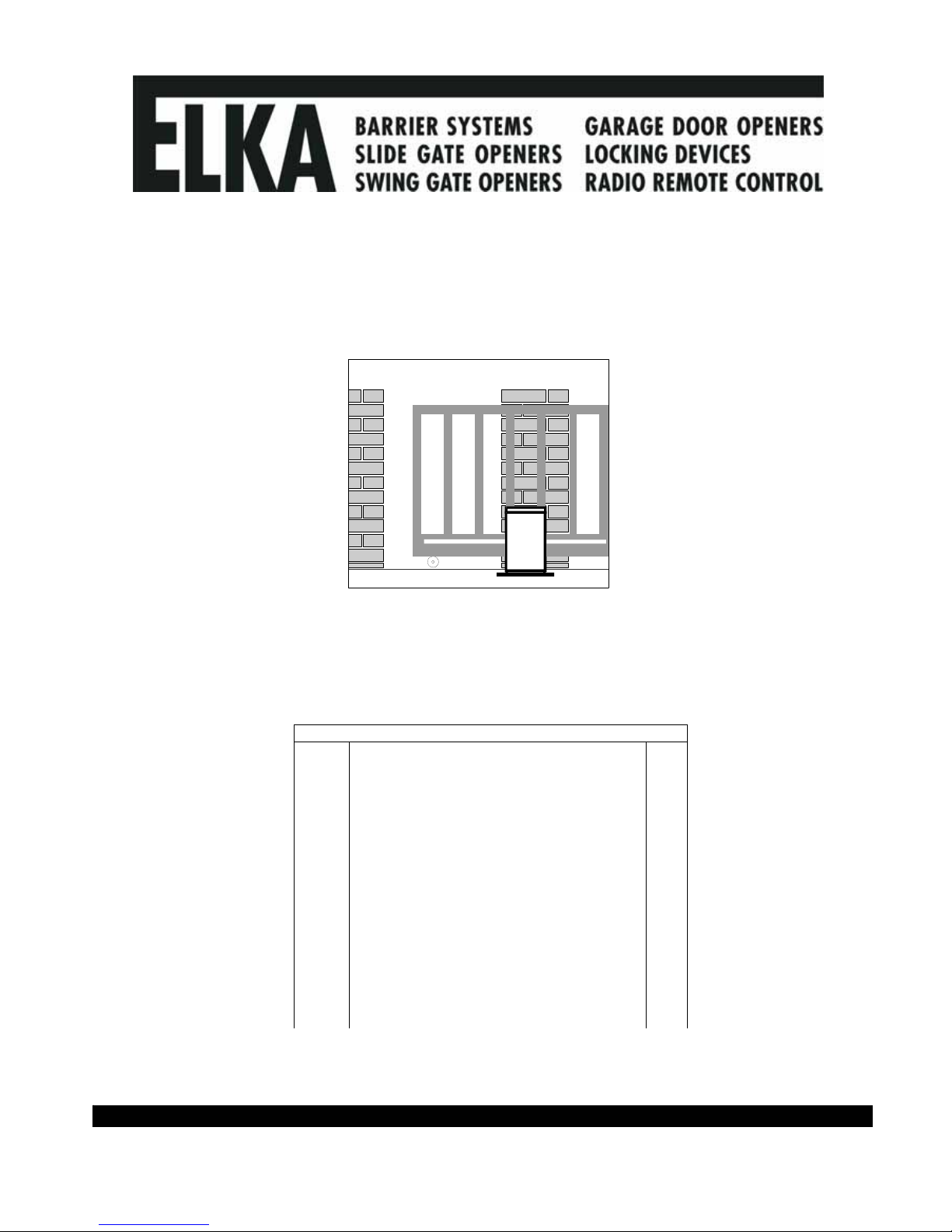
1. Usage
The sliding gate openers EST 204 / 404 and EST 804 are designed for horizontal moving gates either
running on a rail, or cantilever types. Please take note of the valid safety regulations.
2. Technical Data
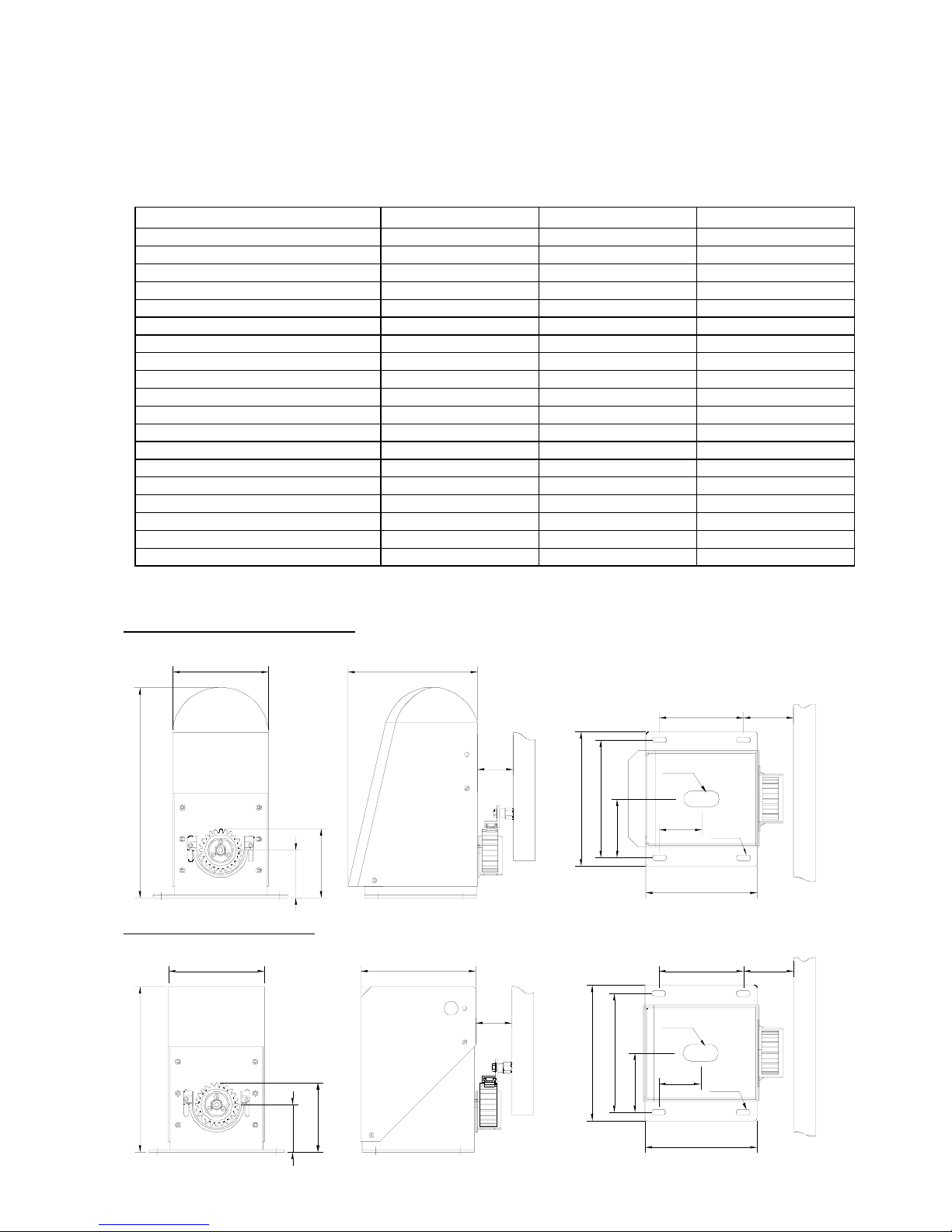
3. Measurements (in mm)
Measurements of EST 204 / 404
Measurements of EST 804
EST 204 EST 404 EST 804
Power supply 230 V 50 Hz 230 V 50 Hz 230 V 50 Hz
Motor Voltage 24 V= 24 V= 24 V=
Force 800 N 800 N 800 N
Maximum weight /length of gate 200 kg / 5 m 400 kg / 6 m 800 kg / 8 m
Approximate speed of movement 0.26m/s 0.17m/s 0.17m/s
Controller MO 56/S MO 56/S MO 43
Soft-Start and Soft-Stop yes yes yes
Input terminals for button BT BT BT, BTA, BTZ, BTG
Input terminal for stop yes, redundant yes, redundant yes
Photo-cell functions 2 modes – testable 2 modes – testable 3 modes
Evaluation of safety contact strips yes, separate open/close yes, separate open/close integrated
Automatic closure selectable (max. 300 s) selectable (max. 300 s) selectable
Partial opening for pedestrians yes, with radio command yes, with radio command optional, radio and button
Prewarning separate for open and close selectable selectable selectable
Traffic lights yes, red / green yes, red / green --Light max. 500W max. 500W --Dead man’s button (hold to run button) yes, in emergency mode yes, in emergency mode selectable
Degree of protection IP56 IP56 IP56
Approximate net weight 11 kg 11 kg 13.5 kg
385
111 - 141
72 - 102
204
10x25
92
65
154
30x65
175 238
77
108
216
246
209175
72 - 102
111 - 141
8.4
65
246
216
108
204
30x65
154 92
77
10x25
302
© 09.02.2006 ELKA-Torantriebe GmbH u. Co. Betriebs KG page 3 EST 204, EST 404, EST 804
4. Installation
End stoppers must be used at the ‘open’ and ‘closed’ positions.
The stopper for the closed position should also prevent that contact strips are squashed if they are
being used.
a) The foundation must be free from frost, and the opener must stand at least 30 mm higher than the
surrounding terrain and at least 100 mm from the gate opening. Decide what cables are required. Make
sure sufficient cable conduit or cable is laid into the foundation. Using the example in section 7.
b) Loosen the four screws and remove the hood.
c) You now have access to all holes for cables and ground fixation.
d) Place the opener with 65 mm distance from the gate with the back parallel to the gate.
e) Mark the middle of the elongated holes on the foundation.
f) Take the opener from the foundation and drill holes for 8 mm diameter plugs or anchor bolts.
g) Lay the 0.5 mm cardboard between the opener and the foundation and secure the opener with the anchor
bolts.
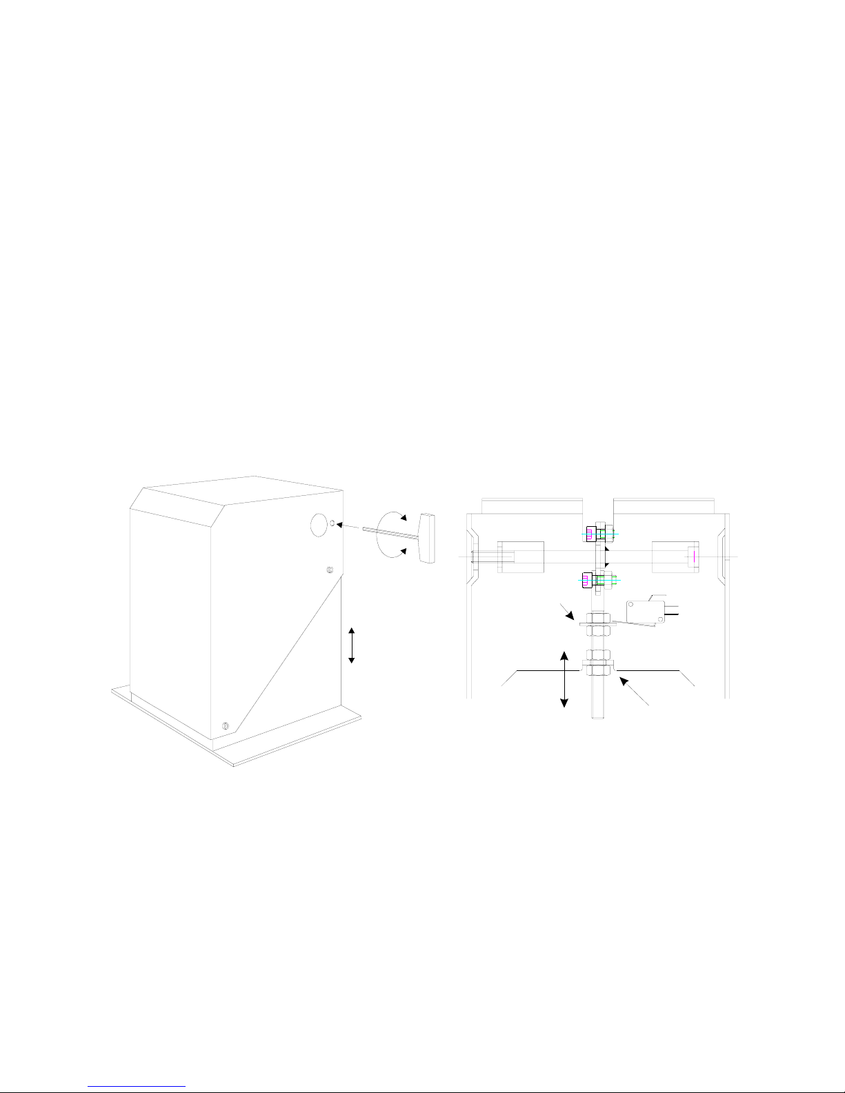
5. Emergency release and height adjustment.
To disengage the opener open the lock (only as option with the EST 804). Insert the 6 mm hexagonal key
into the hole marked X and turn it anticlockwise 180°. The pinion is now disengaged from the rack and the
controller is switched off. The height of the pinion axis is 87mm on delivery and can be altered +15 mm/ 15mm if required. Check that the opener can still be disengaged after adjusting the height.
Pinion
6 mm
hexagonal
key
x
Part to switch
controlle r of f
Switch is off when
disengaged
Motorholder, the height
to the shaft middle is
ca. 87 mm on delivery
Adjustment of the mo tor
holder + or - 15 mm
possible
© 09.02.2006 ELKA-Torantriebe GmbH u. Co. Betriebs KG page 4 EST 204, EST 404, EST 804
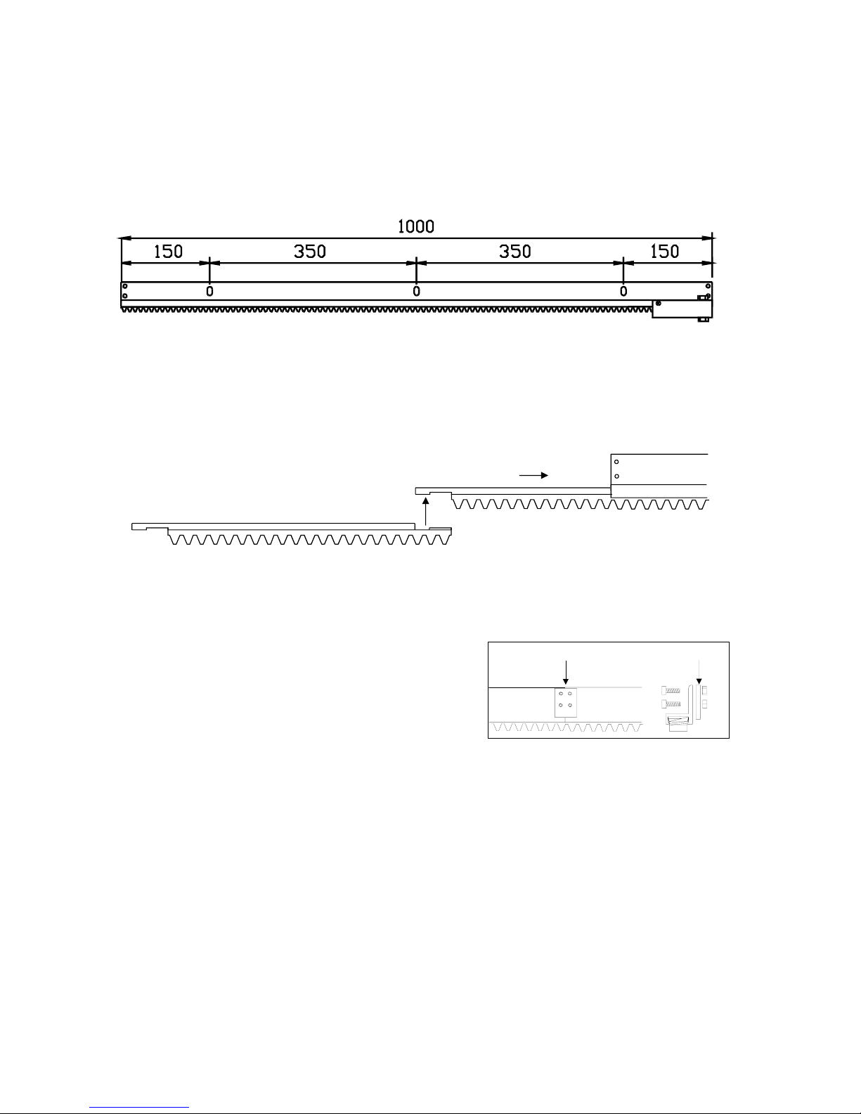
6. Mounting the rack
a) The rack is delivered in lengths of 1 meter. The two lengths with springs are to be mounted on the left and
right end.
No warranty if the rack is used without these springs!
b) Disengage the opener and close the gate manually and mark during closing the mounting height for the
rail on the gate (149 mm above the base plate of the opener).
c) Drill holes Ø 6,5 mm in the intervals as shown below. Tap M8 threads.
d) Screw the distance pieces into the gate.
e) Fix the first length of rack and ensure that the spring is fitted inside. Don’t tighten the screws until the
assembly is complete.
f) Push five plastic rack segments into the rail, hooked together as shown below. Push the segments into
the rail until they are against the spring. The fifth segment will protrude.
g) Hooked six segments of rack together and insert into the next length of rail so that they protrude at both
ends.
h) Hook the protruding end into the protruding end of the first length. Push this rail against the first rail.
j) Screw this length onto the distance pieces.
k) Connect the butt joint of the two lengths of rail with
the connecting piece.
l) Carry on in this way until only the length of rail with
the second spring remains.
m) The last segment of plastic rack must be cut off so that it fits flush against the spring.
n) Re-engage the opener (turn hexagonal key 180° clockwise).
o) Push the rack lightly onto the pinion and check that the teeth are fully engaged. Make any necessary
corrections. Tighten all screws.
p) Disengage the opener and push the gate until the next joint in the rack and carry on as under (o).
q) Carry on in this way until the rack has been checked in its entire length.
r) Remove the cardboard from under the opener.
s) Tighten the securing screws for the opener.
t) A test run of the gate to check the rack will be done during the setup of the controller.
Check that the rack is correctly mounted and that all screws are tight.
The emergency release must work at every position of the gate.
Connecting pi ece for sections of rack
© 09.02.2006 ELKA-Torantriebe GmbH u. Co. Betriebs KG page 5 EST 204, EST 404, EST 804
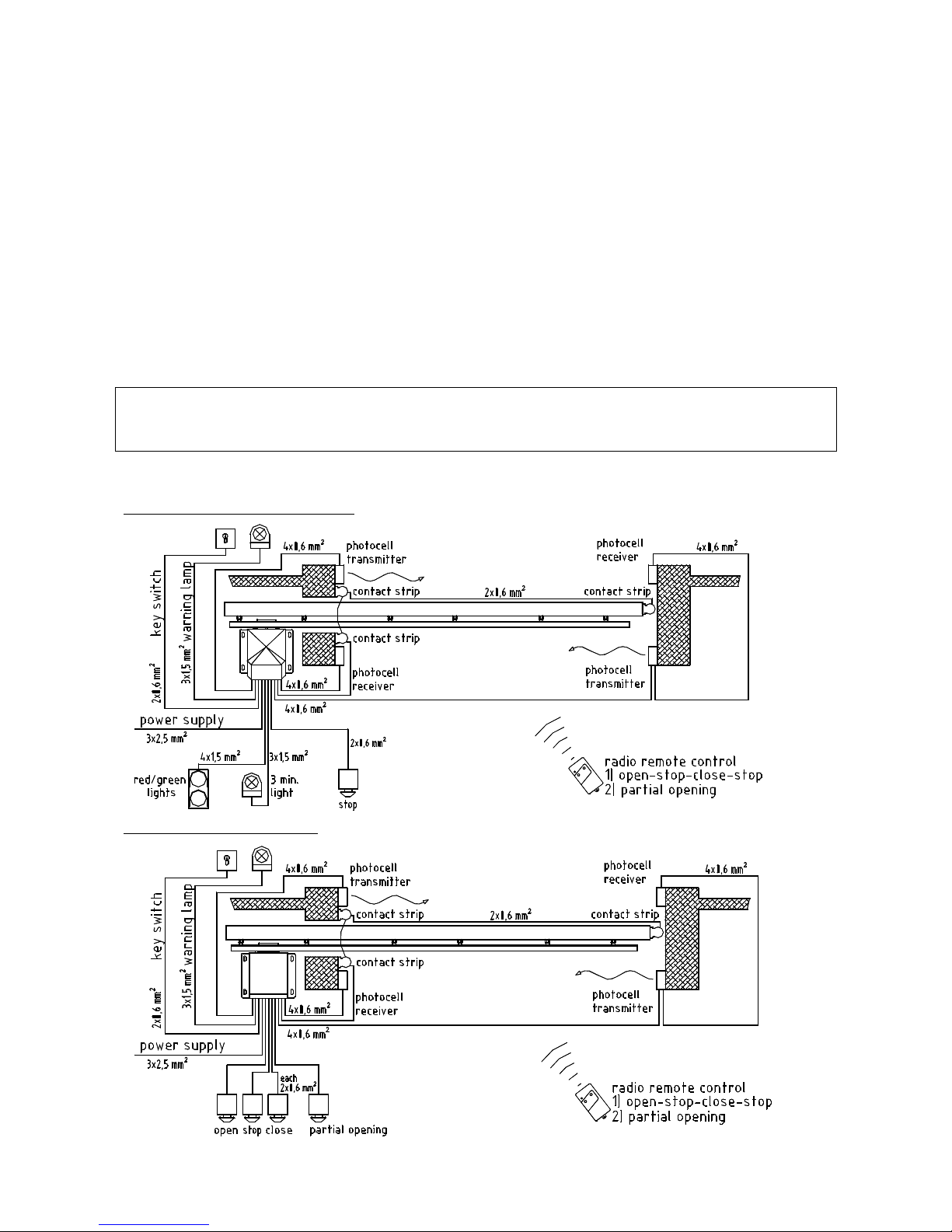
7. Electrical Setup
a) Check if the gate closes to the right or to the left.
If the gate closes to the right as seen from the opener, the motor connectors are: M - green M+ red.
If the gate closes to the left as seen from the opener, the motor connectors are: M - red M+ green
b) Connect all external devices
EST 204 / 404 opener control box MO 56/S section: 8.
EST 804 opener control box MO 43 section: 10.
c) Check the setting of DIP switches for the functions you need.
EST 204 / 404 opener control box MO 56/S section: 9.
EST 804 opener control box MO 43 section: 15.
d) Go through to learning (programming) mode
EST 204 / 404 opener control box MO 56/S section: 11.
EST 804 opener control box MO 43 section: 10.
Caution:
During the learning mode the gate may move automatically several times.
Ensure nobody will enter the gate area.
The opener is ready for use.
Connection example EST 204 / 404
Connection example EST 804
 Loading...