

Elka EST 4004K Installation And Operating Instructions Manual
©06.03.06ELKA-Torantriebe GmbH & Co. Betriebs KG Seite 1 ED 200, ED 202, ED 350, ED 352
Installation and Operating Instructions
Slide Gate Openers
EST 4004K
Contents Page
1. Usage 2
2. Technical data 2
3. Measurements 2
4. Installation 3
4.1 Emergency release 4
5. Electrical connections 4
6. Connection example 5
7. MO 44-2 Controller 6
7.1. Connections 7
7.2. Operating mode 8
7.3. Programming 11
8. Timer module (optional) 12
9. Fault codes 13
10. Setting personal code 13
11. General notes to safety 14
© 27.04.2005 ELKA-Torantriebe GmbH u. Co. Betriebs KG Page 2 EST 4004K
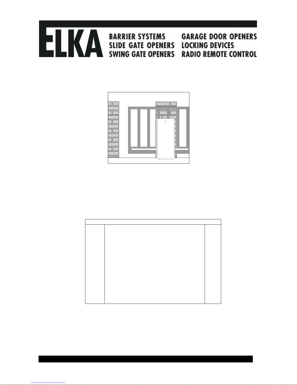
1. Usage
For horizontal moving sliding gates either on rails or as a cantilever, up to the weights stated in the technical
data. Please take note of the valid safety regulations.
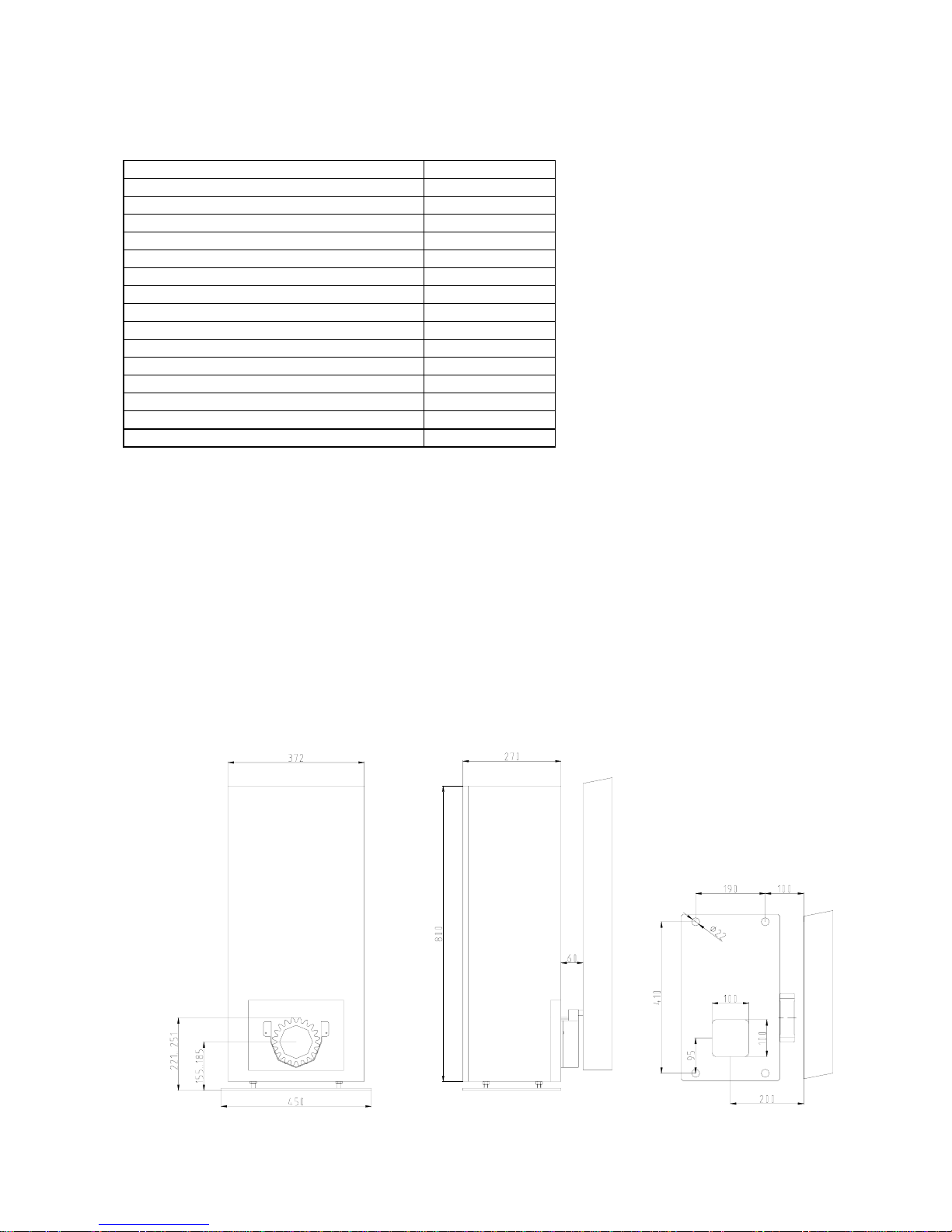
2. Technical Data
EST 4004K
Maximum weight 4000 kg
Recommended maximum length 16 m
Self blocking at open and closed positions yes
Approximate speed 0.18 m/s
Rack Module 6
Duty cycle 75%
Temperature range -20°C to +70°C
Emergency release yes
Possible height adjustment 30 mm
Housing H x W x L 800x372x270 mm
Opener weight 68,0 kg
Power supply 400 Vac / 50 Hz
Power consumption 2.2 kW
Control box MO44-2
Electronic brake no
The MO 44-2 control box has among others the following characteristics:
Safety: Four separate reactions to the photo-cell.
Automatic test of the photo-cells before each gate movement can be enabled.
Integrated evaluator for safety contact strips with 8.2 kΩ terminating resistors.
Actions: Partial opening (e.g. for pedestrians) can be programmed for any position.
Automatic closure can be set separately for completely open and for partially open.
A dead man’s button can also be set.
Separate inputs for OPEN, STOP and CLOSE commands.
The OPEN button can also be transmitted to a further control box (e.g. for a barrier).
Optional timer card for automatic switching between day and night operation.
3. Measurements
© 27.04.2005 ELKA-Torantriebe GmbH u. Co. Betriebs KG Page 3 EST 4004K
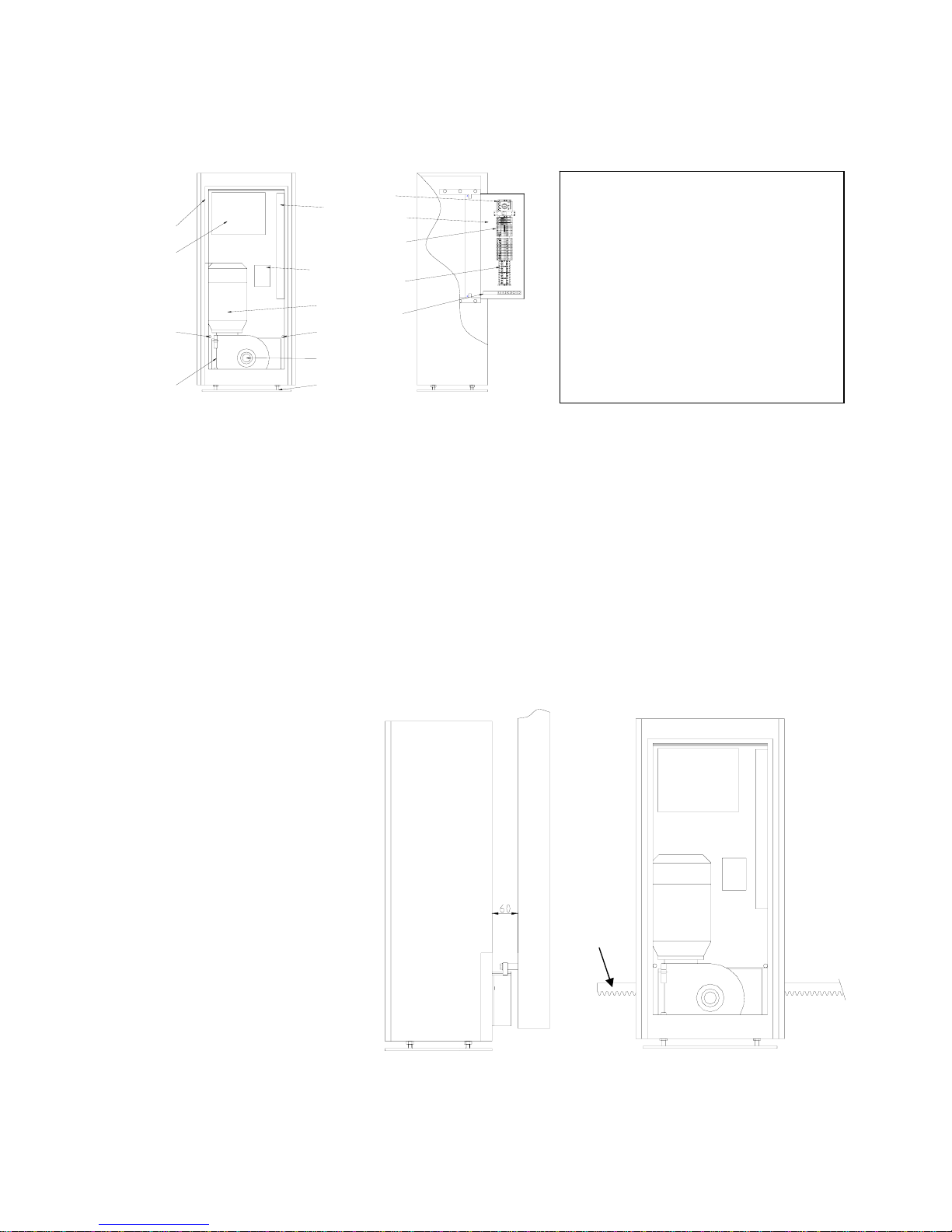
4. Installation
Ensure that the gate is rigid enough, free moving, and suitable for automation (i.e. enough room to
secure the rack on the gate).
Always disconnect the control box before arc welding is carried out.
7
9
5
11
12
1
2
3
4
5
6
10
13NO
14NO
A1
A2
K1
A1 3L25L31L1
A2 4T26T32T1
5L313NO3L21L1
6T314NO
K2
4T22T1
13
13
8
a) Using the example in section 6 decide which cables are required and where the control box is to be
mounted (near the opener). The cable should enter the control box from the bottom.
b) Make sure sufficient cable conduit or cable is laid into the foundation which should be free from frost.
The very bottom opener should be at least 30 mm higher than the surrounding terrain and should be as
near as possible to the pivoting point of cantilever gates.
c) Open the access panel of the opener and remove the height adjustment plate. You now have access to
the elongated ground fixing holes.
d) Place the opener on the foundation parallel to the gate at a distance of 60 mm. Mark the middle of each
hole on the foundation.
e) Fix the opener, either with plugs and screws (M20), or with heavy duty tie bolts.
e) Decide at what height the rack is to be mounted on the gate. You can use the opener with the height
adjustment plate, or if the rack is to be as low as possible, without the adjustment plate.
g) Using the accompanying tubular “T”-bar disengage the opener (anticlockwise disengages and clockwise
re-engages. See section 4.1.)
h) Mount the rack at the required height on the gate. Don’t use the edges of the gate, always use the pinion
of the opener to determine the
height on the gate.
Lay a length of rack horizontally
on the pinion. Mark the height
of the securing points on the gate
through a hole in the rack. You
may push the gate along while
marking in order to gain a marking
line.
The rack and the pinion should fit
together with minimum play but
enough to ensure that the pinion
does not carry the gate.
1 Aluminium housing
2 MO44-2 Control box
3 Cable clip
4 Terminal block
5 Proximity switch
6 Gear box
7 Power outlet
8 Reversing contactor
9 11 pole socket
10 Motor
11 Emergency release SW22
12 Height adjustment
13 Mounting plate
h)
mark
here
d)

© 27.04.2005 ELKA-Torantriebe GmbH u. Co. Betriebs KG Page 4 EST 4004K
i) Drill holes at the appropriate points to secure the rack and then tap an M8 thread. The rack should
protrude 20cm further than the pinion at both limits of gate movement to allow room for the actuators for
open and closed proximity switches.
j) Screw the distance pieces into the gate, which can also be welded in position.
k) Mount the 1 metre lengths of rack. For better results press a third length (with teeth upwards) against the
joints to produce the required distance between lengths.
l) Push the gate completely open and closed and check that it doesn’t jam. If necessary adjust the height
of the rack.
4.1. Emergency release
Open the access panel and using the accompanying tubular “T” bar (SW22) loosen the hex head screw on
the gearbox.
Turning the bar a couple of turns anti-clockwise disengages the gears.
To re-engage the gears, turn the tee wrench clockwise as far as it will go. (see page 3).
5. Electrical Installation
All cables should have at least the suggested cross-sections.
a) Connect the power supply.
b) The opener closes to the left on delivery. The right limit switch (SEZ) stops the movement.
c) If your gate closes to the right swap the motor leads for „open“ and „close“ and swap the leads to the
terminals SEA and SEZ on the control board.
d) Disengage the opener.
e) Close the gate and push the holding plate with magnet along the rack until the
LED SEZ turns off. Fix the holder at this point on the rack so that the magnet
passes the housing at a distance of about 10 mm.
f) Open the gate and push the holding plate with magnet along the rack until the
LED SEA turns off. Fix the holder at this point on the rack so that the magnet
passes the housing at a distance of about 10 mm.
f) Re-engage the opener and carry out a test run with the gate. Use the push
button BT on the controller card which has serial switching OPEN-STOP-
CLOSE-STOP.
Ensure that the LED SEZ turns off when the gate is closed (not SEA)
otherwise you will have malfunctions (e.g. automatic closing becomes
automatic opening).
g) If necessary readjust the actuators for the proximity switches so that the gate
closes exactly.
h) Connect all periphery equipment.
The time required to open or close the door (running time) must be learned.
Caution:
During the learning mode the gate will move automatically several times.
Ensure nobody will enter the gate area.
Learning the running time: (see section 7.3)
Switch the power regulation on with DIP A1 and DIP A2. Choose a low setting, if required it can always be
increased (see section 7.2.).
Press LT for at least 3 seconds The LED DIAG lights.
Press LT twice. The gate closes from any position, opens completely and closes again. Press the LT button
to confirm, the running time and 10 % reserve and the power required are saved.
The opener is ready for use.
Carry on setting operating mode as described in section 7.2.
© 27.04.2005 ELKA-Torantriebe GmbH u. Co. Betriebs KG Page 5 EST 4004K
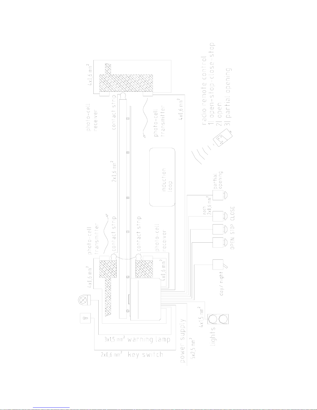
6. Connection example
 Loading...