

Elka EH 30 L, EH 25 L, EH 35 L, EH 40 L, EH 45 L Installation And Operating Instructions Manual
...Page 1
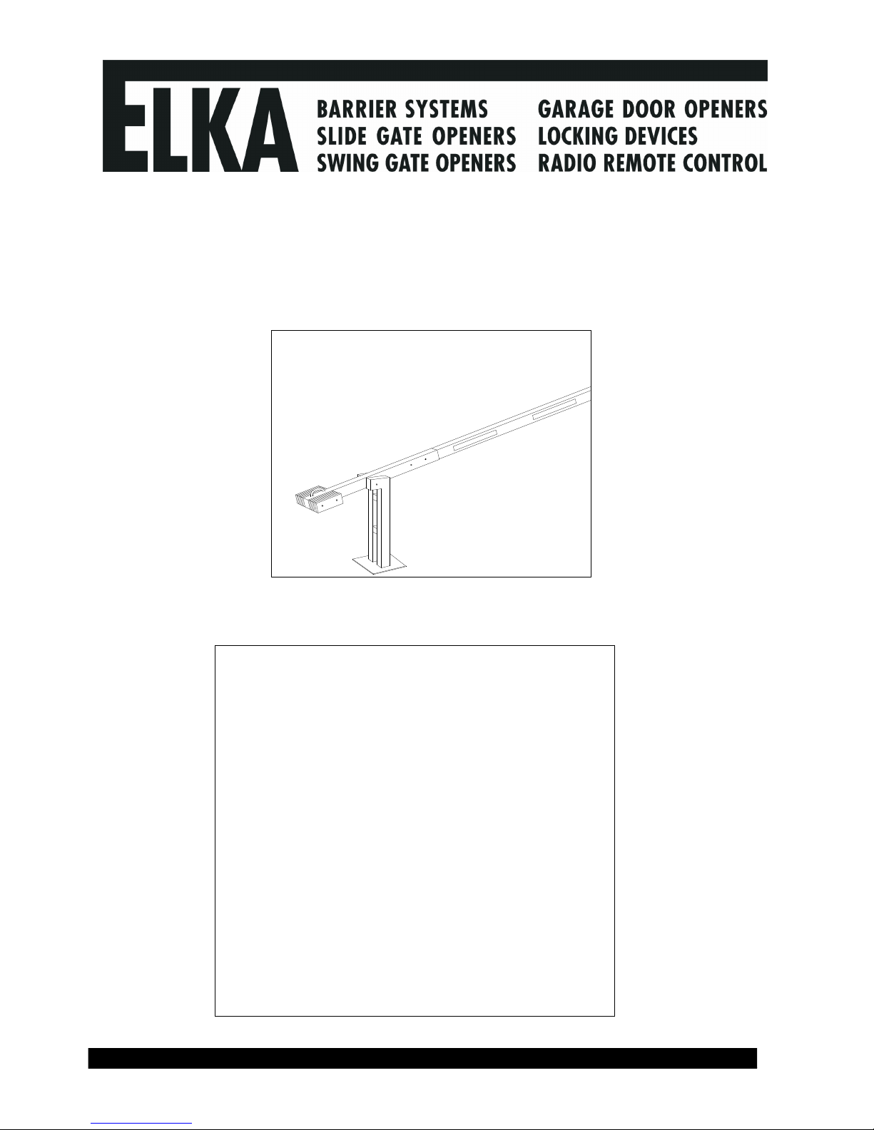
Installation and operating instructions
Manual barriers
Contents Page
1.
Technical Data
2
2.
Installation dimensions
3
3.
Installation
4
3.1.
Installing of manual barrier
4
3.2.
Installing of stabilisation rope
5
4.
Operation
6
5.
General safety notes
8
Page 2

© 26.07.2007 ELKA-Torantriebe GmbH u. Co. Betriebs KG Page 2 Manual barriers
1.
Technical Data
Type L – Boom connector 1,300 mm
Product
EH 25 L EH 30 L EH 35 L EH 40 L EH 45 L EH 50 L EH 55 L EH 60 L EH 65 L EH 70 L EH 75 L
Effective
boom length
(mm)
2,500 3,000 3,500 4,000 4,500 5,000 5,500 6,000 6,500 7,000 7,500
Number of
counter
weights
without
swinging
support
0
2
2
2
4
6
12
14
16
18
20
Number of
counter
weights with
swinging
support
2
4
4
4
6
8
14
16
18
20
22
Total weight
(kg)
without
swinging
support
45
54
55
56
64
73
102
110
119
127
136
Total weight
(kg)
with
swinging
support
54
62
63
64
73
81
110
119
127
136
145
ATTENTION! For a boom length of more than 5.000mm a stabilisation rope is
absolutely necessary! The additional number of counter weights is
already taken into consideration in the above table.
Page 3
© 26.07.2007 ELKA-Torantriebe GmbH u. Co. Betriebs KG Page 3 Manual barriers
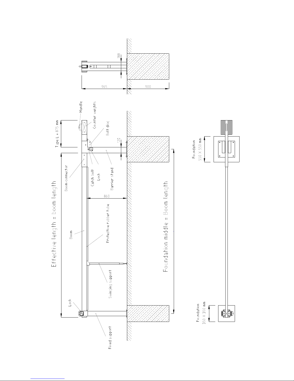
2.
Installation Dimensions
Page 4

© 26.07.2007 ELKA-Torantriebe GmbH u. Co. Betriebs KG Page 4 Manual barriers
Foundation fixed support
350 x 350 mm
Fondation for barrier stand
550 x 550 mm
3.1. Installation
a) The foundation has to be frost-free with a horizontal surface of 550mm x 550mm for the
barrier stand and 350mm x 350mm for the fixed support (optional).
b) Use either bolts to cast into the foundation or after the foundation is hardened, drill holes for
heavy duty dowels. Please make sure the drilling holes for the fixed support are aligned
correctly (130 mm/110 mm).
c) Secure the barrier stand and the fixed support (optional) on the foundation.
d) Disengage and close the barrier. Please engage the barrier in this position.
e) Connect the boom (cut the boom length if required). Please note that a stabilisation rope is
necessary for a boom length of 5,000mm and longer (see 3.2).
f) Fasten the counter weights onto the boom connector. For the quantity of weights please see
table under paragraph 2.
g) Open and close the barrier a few times. Make sure it blocks correctly in the end positions.
Page 5

© 26.07.2007 ELKA-Torantriebe GmbH u. Co. Betriebs KG Page 5 Manual barriers
Guy joints
Trapezoid joints
Turnbuckles
3.2. Installing the stabilisation rope (necessary for boom length 5,000mm and longer)
a) Mount the trapezoid joints at the boom connector left and right with the screws of the barrier
boom. Make sure the alignment is correct (see right side of drawing).
b) Screw the guy joints together with the boom extension onto the barrier boom. Make sure the
alignment is correct (see left side of drawing).
c) Mount the stabilisation ropes (1x left, 1x right) as follows:
1. Connect one end of the wire rope (with dead-eye) to the guy joint, the other end to the
turnbuckle.
2. The turnbuckle has to be mounted to the trapezoid joint.
d) Using the turnbuckles tighten both ropes evenly.
ATTENTION!
The connection screws of the bolt disc
represent a vandalism protection
(predetermined braking point). They prevent
greater damage to the mechanical parts in case
the boom is forced open by pushing.
The connection screws should be replaced with
equivalent screws only (DIN 912 – M6 x 25 – 8.8).
Page 6

© 26.07.2007 ELKA-Torantriebe GmbH u. Co. Betriebs KG Page 6 Manual barriers
4. Operation
4.1. Standard-Barrier
Opening:
1. Pull the catch-bolt out of the bolt-disc.
2. Push the boom connector down using the handle. Move the barrier boom into a
vertical position, until the catch-bolt engages into the bolt disc again.
Closing:
1. Pull the catch-bolt out of the bolt-disc.
2. Pull the boom connector up using the handle. Move the barrier boom into a horizontal
position, until the catch-bolt engages into the bolt disc again.
Page 7

© 26.07.2007 ELKA-Torantriebe GmbH u. Co. Betriebs KG Page 7 Manual barriers
4.2. Barrier with cylinder lock or fire emergency release at the barrier stand or at the fixed
support
Opening:
1. Unlock, depending on the version, the cylinder lock or the fire emergency release at
the barrier stand or at the fixed support.
2. When using locks at the fixed support, first pull the lockage bolt out of the fork of the
support.
3. Pull the catch-bolt out of the bolt-disc.
4. Push the boom connector down using the handle. Move the barrier boom into a
vertical position, until the catch-bolt engages into the bolt disc again.
5. Lock the cylinder lock or the fire emergency release at the barrier stand.
When using locks at the fixed support, return the lockage bolt into the fork of the
support and lock it again with the cylinder lock or with the fire emergency release.
Closing:
1. Unlock, depending on the version, the cylinder lock or he fire emergency release at
the barrier stand or at the fixed support.
2. When using locks at the fixed support, first pull the lockage bolt out of the fork of the
support.
3. Pull the catch-bolt out of the bolt-disc.
4. Pull the boom connector up using the handle. Move the barrier boom into a horizontal
position, until the catch-bolt engages into the bolt disc again.
5. Lock the cylinder lock or the fire emergency release at the barrier stand.
When using locks at the fixed support, return the lockage bolt into the fork of the
support and lock it again with the cylinder lock or with the fire emergency release.
Page 8

© 26.07.2007 ELKA-Torantriebe GmbH u. Co. Betriebs KG Page 8 Manual barriers
5. General notes of safety
These operating instructions must be available on site at all times. It should be read thoroughly by all persons
who use, or service the appliances. Improper usage or servicing or ignoring the operating instructions can be a
source of danger for persons, or result in material damage. If the meaning of any part of these instructions isn’t
clear, then please contact ELKA Torantriebe GmbH u. Co. Betriebs KG before you use the appliance.
This applies to all setup procedures, fault finding, disposal of material, care and servicing of the appliance.
The accident prevention regulations and applicable technical regulations (e.g. safety or electrical) and
environment protection regulations of the country in which the appliance is used also apply.
All repairs on the appliances must be carried out by qualified persons. ELKA Torantriebe GmbH u. Co. Betriebs
KG accepts no liability for damage which is caused by using the appliance for purposes other than those for
which it is built.
ELKA Torantriebe GmbH u. Co. Betriebs KG cannot recognise every possible source of danger in advance. If
the appliance is used other than in the recommended manner, the user must ascertain that no danger for
himself or others will result from this use. He should also ascertain that the planned use will have no
detrimental effect on the appliance itself. The appliance should only be used when all safety equipment is
available and in working order. All faults which could be a source of danger to the user or to third persons must
be eliminated immediately. All warning and safety notices on the appliances must be kept legible.
All electrical periphery equipment which is connected to the appliance must have a CE Mark, which ensures
that it conforms to the relevant EEC regulations. Neither mechanical nor electrical alterations to the appliance,
without explicit agreement of the manufacturer, are allowed. All alterations or extensions to the appliance must
be carried out with parts which ELKA Torantriebe GmbH u. Co. Betriebs KG have defined as suitable for such
alterations, and be carried out by qualified personnel.
Any contravention of these conditions revokes the manufacturer’s guarantee and also the CE Mark and the
user is alone responsible for the consequences.
Our service department is available to answer all queries about these conditions and, of course, about our
appliances.
We reserve the right to make technical improvements without prior notice.
The operation of the system within CEN countries must also be conformant with the European safety-relevant directives
and standards.
 Loading...