

Page 1
Installation and Operating Instructions
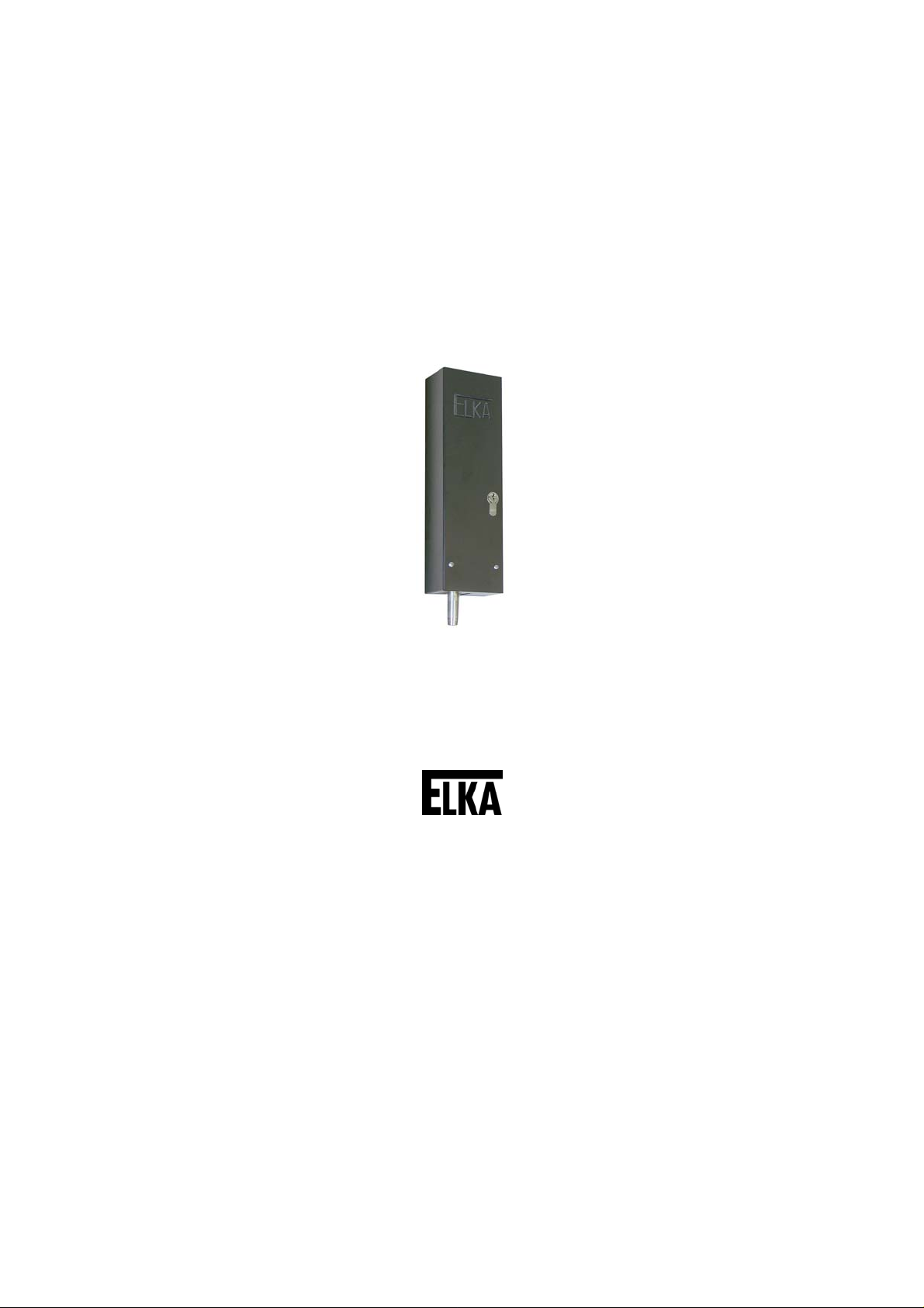
Electromagnetic Bolt
E 205
Accessories
Translation of original operating manual
D-ID: V2_0 – 03.13
ELKA-Torantriebe GmbH u. Co. Betriebs KG
Dithmarscher Str. 9 Fax: +49-(0) 48 61 - 96 90-90
25832 Tönning E-mail: info@ELKA-Torantriebe.de
Germany Internet: www.ELKA-Torantriebe.de
Phone: +49-(0) 48 61 - 96 90-0
Page 2

5
Elektroschloss E 20
Index of contents
1 Preface 2
1.1 General notes 2
1.2 Copyright 3
1.3 Information regarding installation instruction 3
2 Electromagnetic Bolt E 205 4
2.1 Usage 4
2.2 Technical data 4
2.3 Electrical connection 4
2.4 Installation measurements 8
2.5 Emergency release during power failure 9
1
Page 3
5
2
1 Preface
1.1 General notes
These operating instructions must be available on site at all times. It should be
read thoroughly by all persons who use, or service the appliances. Improper
usage or servicing or ignoring the operating instructions can be a source of
danger for persons, or result in material damage. If the meaning of any part of
these instructions isn’t clear, then please contact ELKA-Torantriebe GmbH u.
Co. Betriebs KG before you use the appliance.
This applies to all setup procedures, fault finding, disposal of material, care
and servicing of the appliance. The accident prevention regulations and
applicable technical regulations (e.g. safety or electrical) and environment
protection regulations of the country in which the appliance is used also apply.
All repairs on the appliances must be carried out by qualified persons. ELKATorantriebe GmbH u. Co. Betriebs KG accepts no liability for damage which is
caused by using the appliance for purposes other than those for which it is
built.
ELKA-Torantriebe GmbH u. Co. Betriebs KG cannot recognise every possible
source of danger in advance. If the appliance is used other than in the
recommended manner, the user must ascertain that no danger for himself or
others will result from this use. He should also ascertain that the planned use
will have no detrimental effect on the appliance itself. The appliance should
only be used when all safety equipment is available and in working order. All
faults which could be a source of danger to the user or to third persons must
be eliminated immediately. All warning and safety notices on the appliances
must be kept legible.
All electrical periphery equipment which is connected to the appliance must
have a CE Mark, which ensures that it conforms to the relevant EEC
regulations. Neither mechanical nor electrical alterations to the appliance,
without explicit agreement of the manufacturer, are allowed. All alterations or
extensions to the appliance must be carried out with parts which ELKATorantriebe GmbH u. Co. Betriebs KG have defined as suitable for such
alterations, and be carried out by qualified personnel. Please note that with
any alteration of the product, no matter whether mechanical or electrical, the
warranty expires and the conformity is revoked. Only the use of ELKA
accessories and original ELKA spare parts is allowed. In case of any
contravention ELKA disclaims liability of any kind.
INFORMATION!
The operation of the system within CEN countries must also be conformant
with the European safety-relevant directives and standards.
We reserve the right to make technical improvements without prior notice.
Elektroschloss E 20
Page 4

5
3
1.1.1 Symbol explanation
Remarks regarding the safety of persons and the gate opener itself are
marked by special symbols. These remarks have to be absolutely observed in
order to avoid accidents and material damage.
DANGER!
…points to an imminent dangerous situation, which can cause death or
serious injuries if it is not avoided.
WARNING!
…points to a potentially dangerous situation, which can cause death or
serious injuries if it is not avoided.
ATTENTION!
…points to a potentially dangerous situation, which can cause minor or
slight injuries if it is not avoided.
ATTENTION!
…points to a potentially dangerous situation, which can cause property
damage if it is not avoided.
REMARK!
Important notice for installation or functioning.
Elektroschloss E 20
1.2 Copyright
The operating manual and the contained text, drawings, pictures, and other
depictions are protected by copyright. Reproduction of any kind – even in
extracts – as well as the utilization and/or communication of the content
without written release certificate are prohibited. Violators will be held liable for
damages. We reserve the right to make further claims.
1.3 Information regarding installation instruction
This document is to be used as installation instruction for partly completed
machinery (according to machinery directive 2006/42/EG, article 13, (2)).
Page 5

5
2 Electromagnetic Bolt E 205
2.1 Usage
Electromagnetic bolt E 205 to lock swing gates. The bolt locks either
downwards or to the side.
When using the electromagnetic bolt sidewards, it must be protected from
moisture by a cover (on site).
2.2 Technical data
Power supply 24Vac (Alternating current)
Maximum current approx. 6.0A during stroke movement
approx. 1.0A during stop position
Degree of protection IP43
Emergency release With key (cylinder lock)
Elektroschloss E 20
Measurements (W x H x L) 94 x 295 x 58mm
Stroke 50mm
Table 1
2.3 Electrical connection
The cross section of the cable to the bolt depends on the distance between
the controller and the electromagnetic bolt:
up to 50m: 1.5mm
Please note that with an increasing distance between controller and swing
gate the range of the radio remote control decreases, since the radio remote
control receiver is plugged onto the controller.
2
4
Page 6

5
5
Elektroschloss E 20
2.3.1 Electrical connection MO 36 when using with out warning
light
WARNING!
Danger by electrical voltage!
Danger of electric shock.
The device should be connected to the supply voltage (230Vac) by a
qualified electrician only.
Drawing 1
Directly connectable through the warning light connection and the main
transformer of the controller MO 36.
Connect the electromagnetic bolt E 205 to the transformer clamp of the main
board (secondary winding of the toroid transformer). The supply of the toroid
transformer is switched over one conductor of the warning light connection.
Please set the pre-warning time for both directions to 4 seconds (learning
sequence P8).
Page 7

5
6
Elektroschloss E 20
2.3.2 Electrical connection MO 36 when using with warning light
(230Vac)
WARNING!
Danger by electrical voltage!
Danger of electric shock.
The device should be connected to the supply voltage (230Vac) by a
qualified electrician only.
Drawing 2
Connect the electromagnetic bolt E 205 to the transformer clamp of the main
board (secondary wiring of the toroid transformer). The supply of the toroid
transformer is switched over one conductor of the warning light connection.
Set the pre-warning time for both directions to 4 seconds (learning sequence
P8).
When warning light and the E 205 shall be used, connect the warning light as
shown above.
Page 8

5
7
Elektroschloss E 20
2.3.3 Electrical connection MO 32, MO 34 and other controllers
WARNING!
Danger by electrical voltage!
Danger of electric shock.
The device should be connected to the supply voltage (230Vac) by a
qualified electrician only.
Installation example controller MO 34
Drawing 3
With other controllers the power supply has to come through a separate
transformer from a connection which is activated at every gate movement, e.g.
warning light connection.
Page 9

5
8
2.4 Installation measurements
Installation for locking downwards. The length of the pin is 50mm from the
lower edge of the housing.
Elektroschloss E 20
Drawing 4
Page 10

5
9
2.5 Emergency release during power failure
Release the bolt by turning the key clockwise (approx. 4 turns) until the pin
has reached its upper position.
ATTENTION!
Using the key move the pin into the uppermost (emergency released)
position or into the lowest (engaged) position only. Do not move the pin
into an in-between position.
Engage by turning the key counter-clockwise.
The enclosed single cylinder lock can be replaced by another single cylinder
lock or by a double cylinder lock on site (e.g. from a master key system).
When using a double cylinder lock the lock can be released from inside or
outside the gate as long as there is an opening for the double profile cylinder
in the gate leaf.
Elektroschloss E 20
 Loading...