

Page 1
ElkConnect
®
Center for setup videos and detailed instructions.
Scan the code to visit the Alarm Engine® Knowledge
About This Guide
This guide will provide a basic overview of the configuration of the E27 Alarm Engine using the ElkConnect app and
portal. Please refer to the Alarm Engine Knowledge Center for detailed configuration instructions.
Getting Started
Before proceeding, please review the checklist below:
Do you have an account/login for the ElkConnect cloud portal?
• E27 controls must be registered and assigned through the ELK Connect cloud portal. You must complete the ELK Connect account
application to setup your account.
Have you downloaded the ElkConnect App?
CONFIGURATION GUIDE
• ElkConnect is used to configure the E27 Alarm Engine. This app is available for Android and iOS devices. Search Google Play or App
Store for ElkConnect.
Connecting to the system
1. Ensure the E27 control is connected to a network with Internet access.
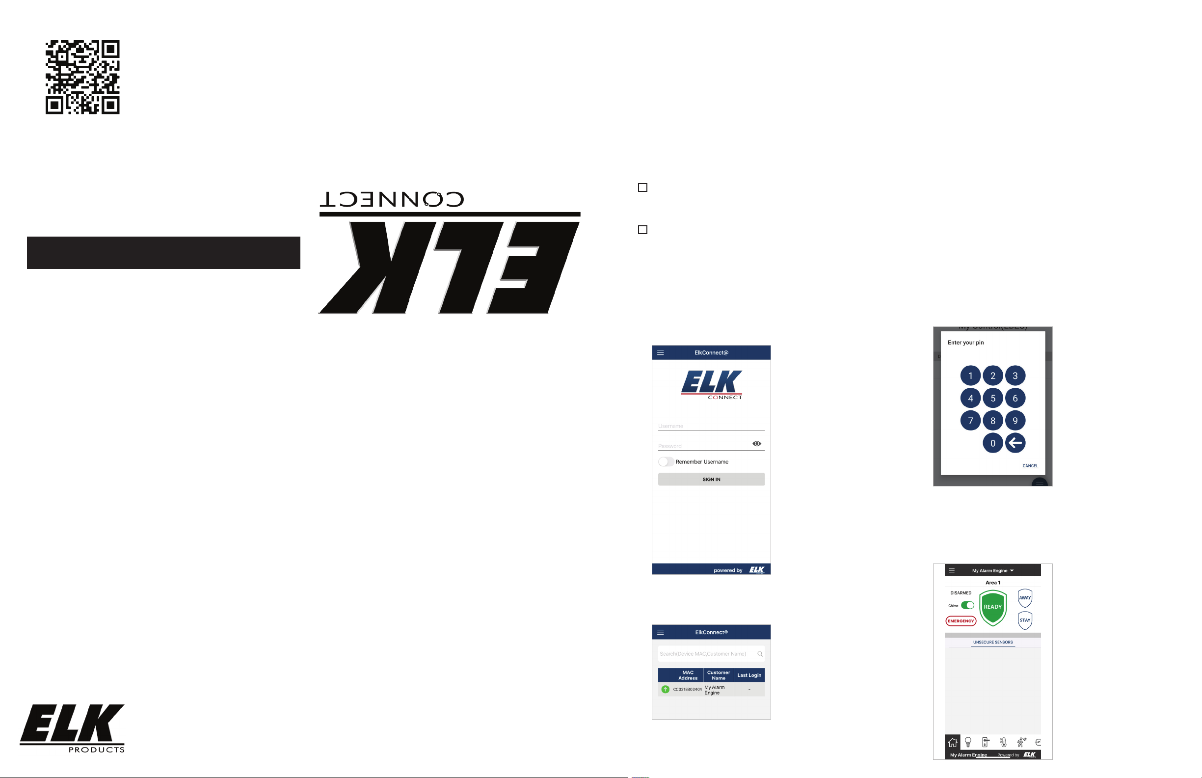
2. Launch ElkConnect app on the mobile device. Log into the app
using your Installer username and password (this is the same as your
elkconnect.com username and password)
4. When prompted to enter your pin, enter the default installer code of
1728.
If connecting via Wi-Fi, please refer to ELK-AEWF instructions for next steps.
5. ElkConnect will establish a connection with the E27 control and
display the Home screen. This screen allows you to view the status of
each area and change the arm state. It allows an emergency alarm to
be activated. This screen also allows the chime feature to be turned
on/o.
PO Box 100 3266 US Hwy 70 West
Hildebran, NC 28637
Phone 828-397-4200 https://www.elkproducts.com
3. A list of the E27 controls associated with your installer account will be
displayed with MAC addresses and system names. Locate the desired
control and tap to connect.
Printed In USA
L700 9/12/2022
Page 2
Configuring the system
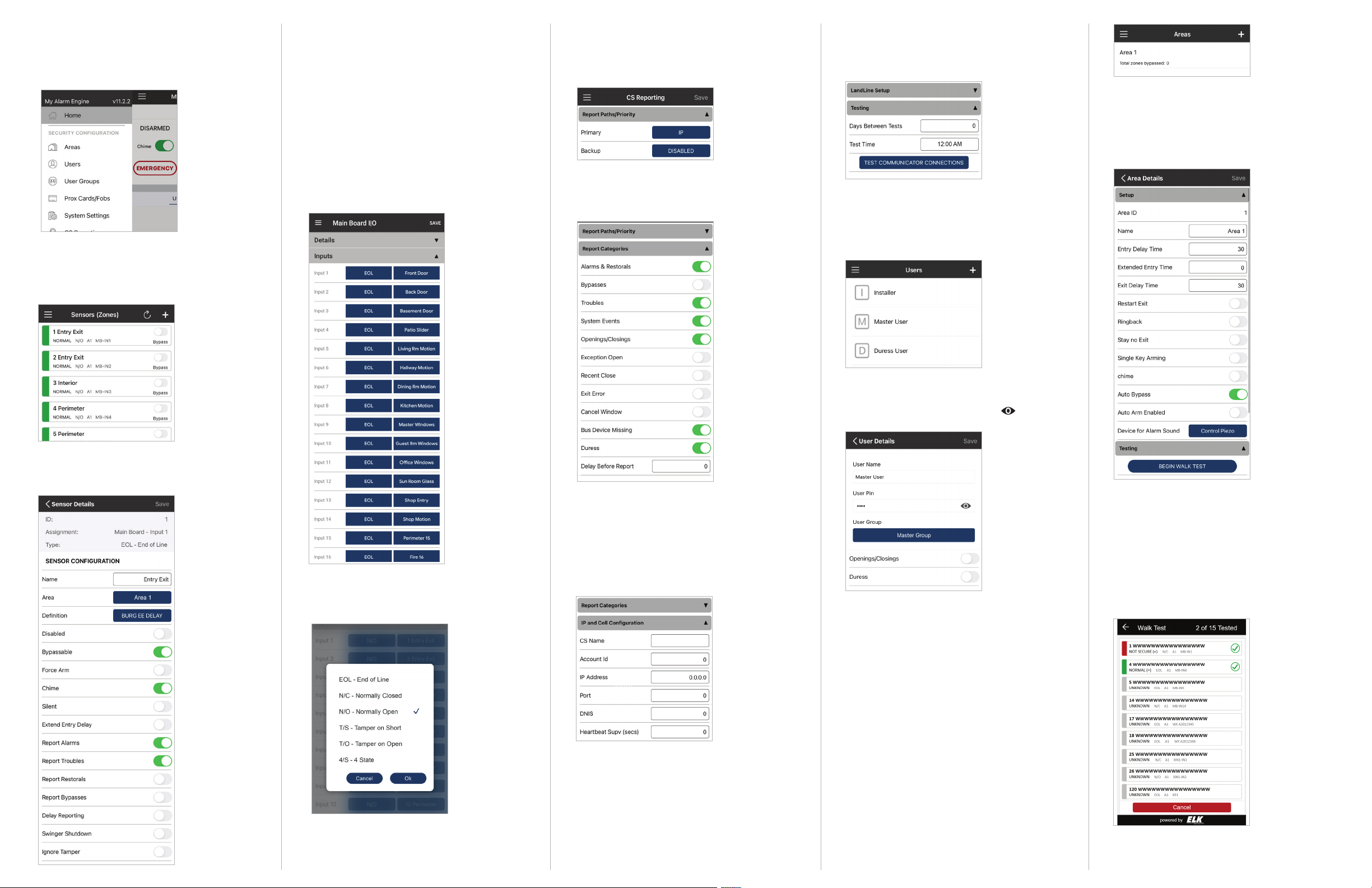
To access configuration menus within the app, tap the
menu icon in the upper le corner. A list of main menu
options will be displayed.
Sensors/Zones/Inputs
1. To configure the main board zones, select Sensors from
the menu. The Zones screen displays a list of zones,
showing current status.
Tap the text field, button or toggle to the right of an item
to change it. Aer making the desired changes, tap the
SAVE button at the bottom of the screen to save the
changes to the E27 control. Tap OK on the confirmation
prompt.
3. By default, all main board zones are configured to
require a 2.2k ohm end-of-line resistor. However, this
configuration can be changed to several other states, such
as normally open, normally closed, etc. To change the
zone hookup type, choose Main Board I|O from the main
menu.
4. Tap Inputs to expand that section. Inputs 1-16 are
displayed, showing the hookup type on the le button
and the name of the zone assigned to the input on the
right button.
IP Reporting
1. To configure IP reporting, choose CS Reporting from the
main menu. Tap Priority. Tap Disabled beside Primary.
Choose IP, then tap OK.
2. Tap Report Categories to expand that section. A list of
reportable events/categories will be displayed. To enable/
disable an item, tap the toggle button to the right of the
item.
7. Test the communicator settings by tapping the TEST
COMMUNICATOR CONNECTIONS button. A prompt will be
displayed indicating the test has started. Tap OK. Verify
CS received the test signal.
Changing a User Code
1. It is strongly recommended the default installer and
user code values be changed. To change a user code,
choose Users from the main menu. A list of Users will be
displayed.
2. A new area can be added by tapping the add icon in
the upper right corner of the screen.
3. All area settings can be configured from the Area details
screen including Area name, entry and exit delay times,
alarm sounder settings, etc. Aer making desired
changes, tap SAVE at the top to save the area settings to
the E27 control. Tap OK on the confirmation prompt.
+
2. To make changes to a sensor, tap the zone name. The
Sensor Details screen will be displayed. From this screen
the sensor name, definition and other attributes can be
configured.
5. Tap the Hookup type button next to the input that needs
to be changed. A list of hookup types will be displayed.
Tap the desired hookup type, then tap OK. Repeat this
process for any other inputs that need to be changed.
6. Once all required changes are made, tap the SAVE button
to save the changes to the E27 control. Tap OK on the
confirmation prompt.
3. Tap IP and Cell Configuration to expand. Central
Monitoring Station(CS) IP receiver information will be
entered in this section.
4. This section will allow the entry of the Account ID, IP
Address, Port and DNIS. This information is provided by
the Central Monitoring Station (CS). If supervision and
encryption are required by the CS, they will also provide
the values for these fields.
5. It is strongly recommended to configure the E27 control
to send a periodic test signal. Tap Testing to expand this
section. Enter the desired value in the Days Between Tests
field. Click the button beside Test Time to set the time of
day the test will occur.
6. Aer making all the necessary changes on the CS
Reporting page, tap the SAVE button to save the changes
to the E27 Control. Tap OK on the confirmation prompt.
2. Tap a user to view current settings and make changes.
The user code will be hidden and displayed as ••••. If you
wish to view the existing code, tap the un-hide icon to
the right of the user code.
3. To change the code, tap the existing code. A number pad
will be displayed, allowing you to clear out the existing
code and enter a new 4 digit code. Then tap the check/
enter button. Tap the SAVE button to save the user to the
E27 control. Tap OK on the confirmation prompt.
Adding a User Code
1. Choose Users from the main menu. Tap the add icon
in the upper right corner of the screen.
2. Enter a User Name and 4 digit user code. Tap the
User Group button and select a user group (for more
information on User Groups, please refer to the E27
Knowledge Center). Tap SAVE at the top to save the user
to the E27 control. Tap OK on the confirmation prompt.
+
Areas
1. To configure Areas, choose Areas from the main menu. A
list of areas will be displayed. Tap an area to view and edit
the area configuration.
Peforming a Walk Test
1. It is strongly recommended to perform a walk test
aer completeing system configuration to verify the
operation of each sensor in an area. To begin a walk test,
choose Areas from the main menu. A list of areas will be
displayed. Tap the area to be tested. Expand the testing
section and tap Begin Walk Test.
2. A list of sensors assigned to the area will be presented
with an indication of their test status. This page also
displays a count of tested/total sensors in the area.
3. Exercise each sensor and verify it is functioning correctly.
When testing has been completed, tap the Cancel button.
 Loading...