

Page 1

IC7.1/IC4000
ASSEMBLY GUIDE
Page 2
32
ASSEMBLY
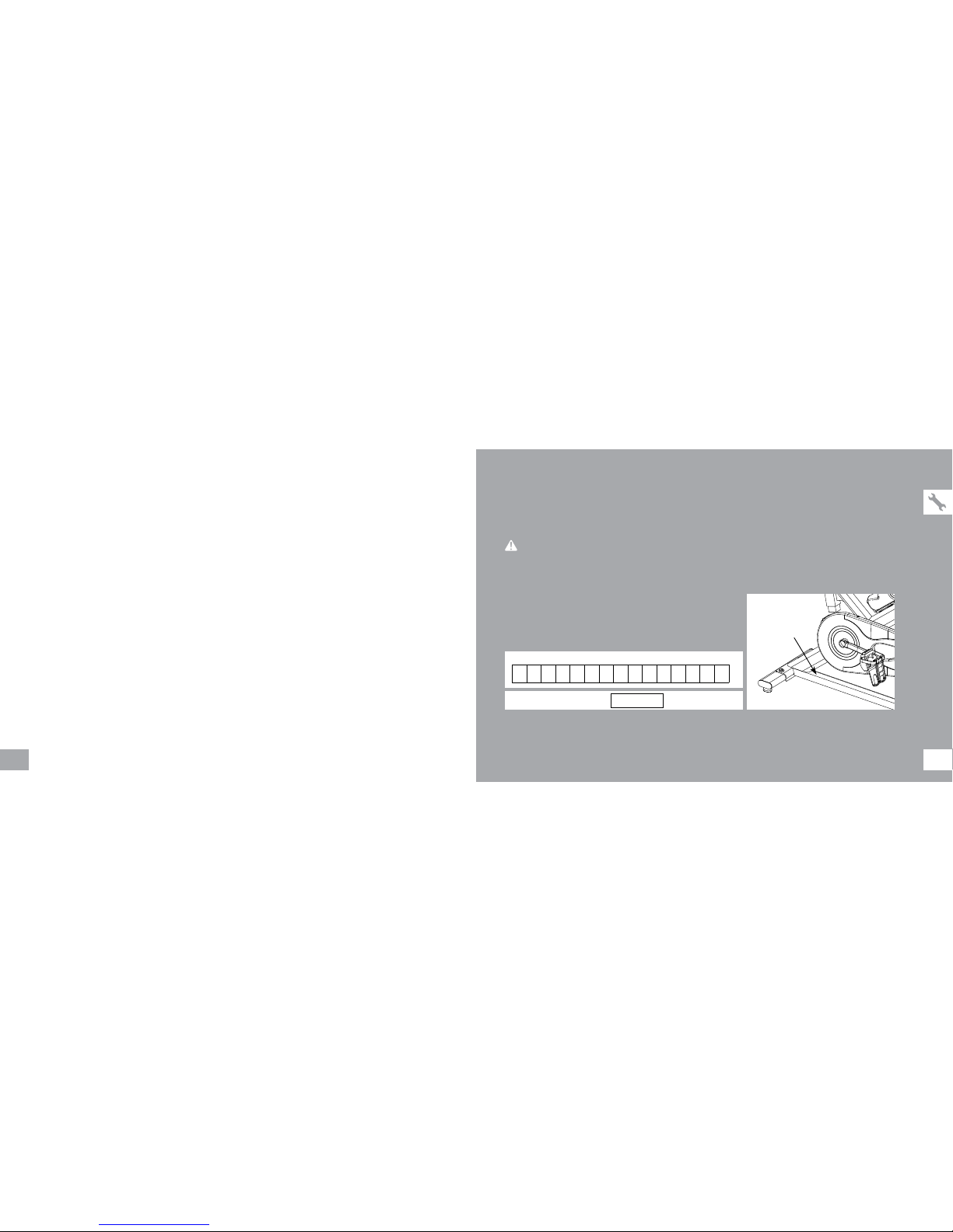
There are several areas during the assembly process that special attention must be paid. It is very important to follow the
assembly instructions correctly and to make sure all parts are firmly tightened. If the assembly instructions are not followed
correctly, the indoor cycle could have parts that are not tightened and will seem loose and may cause irritating noises. To
prevent damage to the indoor cycle, the assembly instructions must be reviewed and corrective actions should be taken.
Before proceeding, find your indoor cycle’s serial number located on
the rear base frame of the cycle and enter it in the space provided below.
ENTER YOUR SERIAL NUMBER IN THE BOX BELOW:
» Refer to the SERIAL NUMBER and MODEL NAME when calling for service.
» Be sure to enter both the SERIAL NUMBER and MODEL NAME on your warranty card.
SERIAL NUMBER:
MODEL NAME:
HORIZON INDOOR CYCLE
WARNI NG
Page 3
54
If you have questions or if there
are any missing parts, contact your
local dealer. Contact information
may be located on the back panel
of this manual or on warranty card.
UNPACKING
Due to the weight of the indoor cycle, it is
recommended that two persons perform the
assembly. Set the indoor cycle in a cleared
area and remove all packing materials; do not
dispose of the packing materials until assembly is
completed.
NOTE: During each assembly step, ensure that
ALL nuts and bolts are in place and partially
threaded in before completely tightening any
ONE bolt.
NOTE: A light application of grease may aid in
the installation of hardware. Any grease, such as
lithium bike grease is recommended.
NEED HELP?
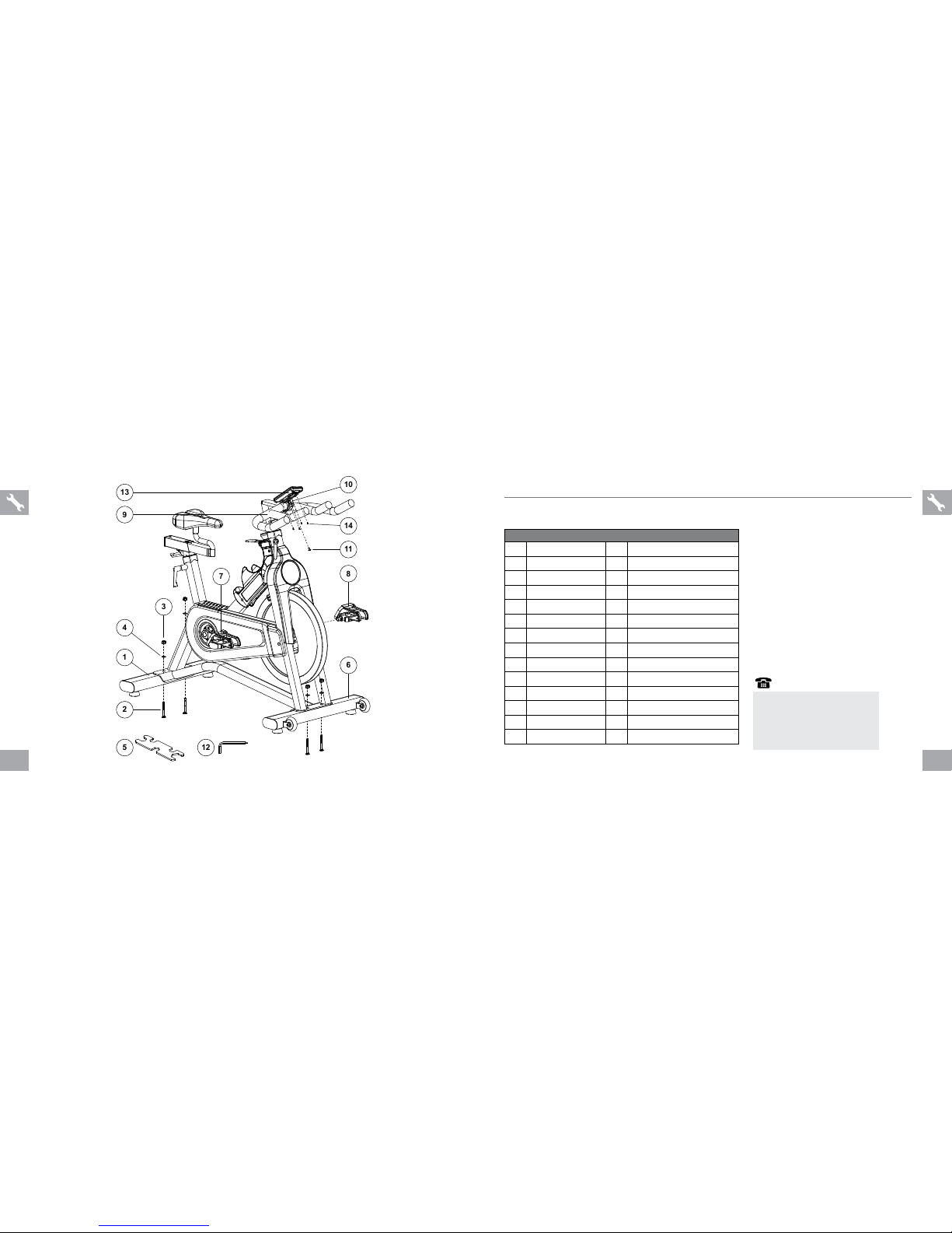
PRE ASSEMBLY
1
4
3
2
81114
6
9
13
10
5127
AS S E MB LY PA RTS L IST:
ITEM DESCRIPTION QTY SPECIFICATION
1 Rear Stabilizer 1 Without 2 transportation wheels
2 Carriage Bolt 4
3 Flange Nut 4
4 Washer 4
5 Adjustable Wrench 1
6 Front Stabilizer 1 With 2 transportation wheels
7 Pedal (R) 1 Right threaded
8 Pedal (L) 1 Left threaded
9 Handlebar 1 Chrome & PVC dipping
10 Console Bracket 1
11 Screw 1
12 Allen Wrench 1
13 Console 1
14 Screw 4
Page 4
76
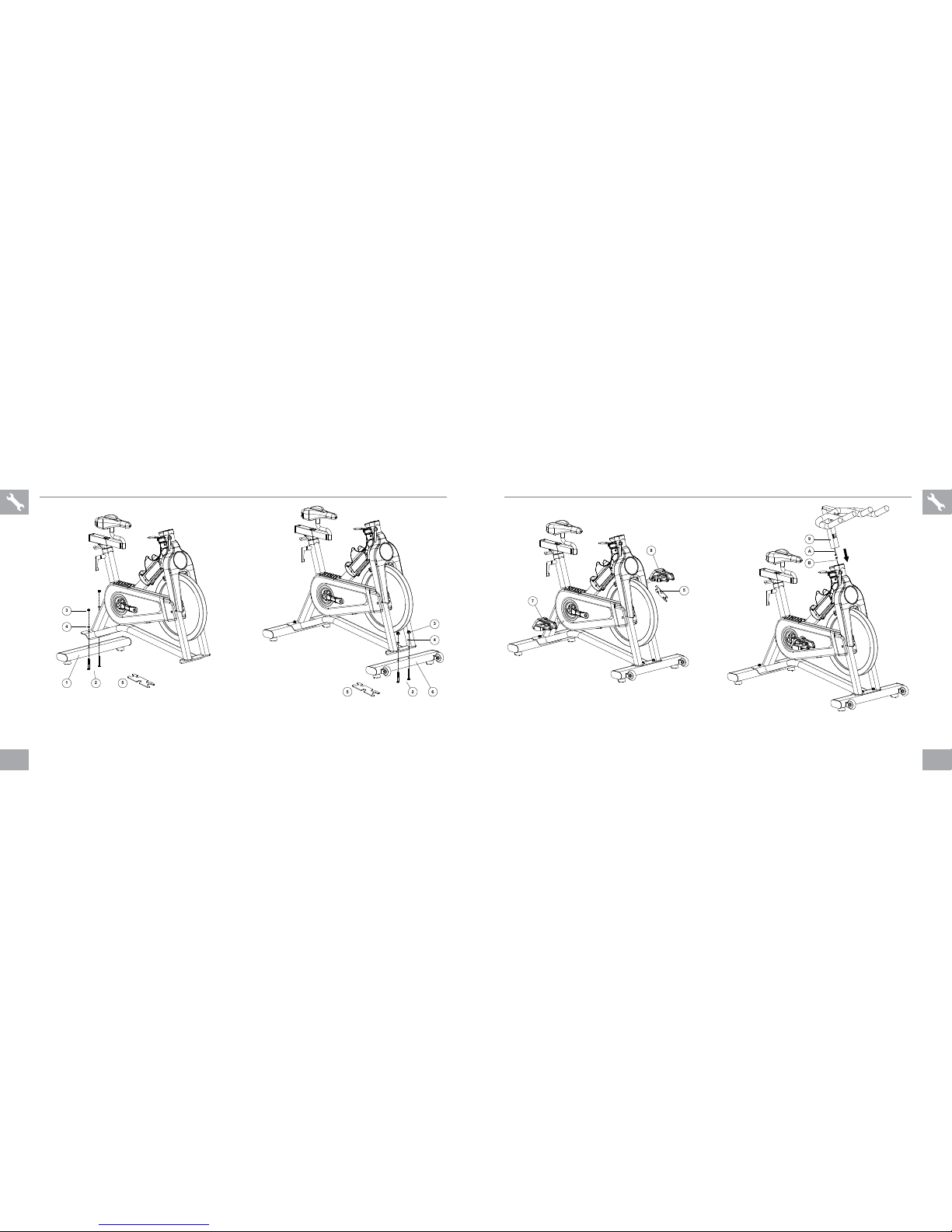
ASSEMBLY STEP 3 & 4ASSEMBLY STEP 1 & 2
1 Attach the rear stabilizer (1) to the frame using 2 flange
nuts (3), 2 washers (4) and two carriage bolts (2), and
secure firmly using the adjustable wrench (5).
2 Attach the front stabilizer (6) to the frame using 2 flange
nuts (3), 2 washers (4) and two carriage bolts (2), and
secure firmly using the adjustable wrench (5).
4
1
235
526
4
3
3 Thread the left pedal (8) that has “L” on the spindle to the
left side arm of the cycle using the adjustable wrench (5).
Please note that the L pedal is left-hand threaded which
needs to be turned counter clockwise to tighten.
Thread the right pedal (7) that has “R” on the spindle
to the right side arm of the cycle using the adjustable
wrench (5). Please note that the R pedal is right-hand
threaded which needs to be turned clockwise to tighten.
4 Attach console cable (A) to console cable (B). Insert
handlebar (9) into bike frame.
8
5
7
9AB
Page 5
98
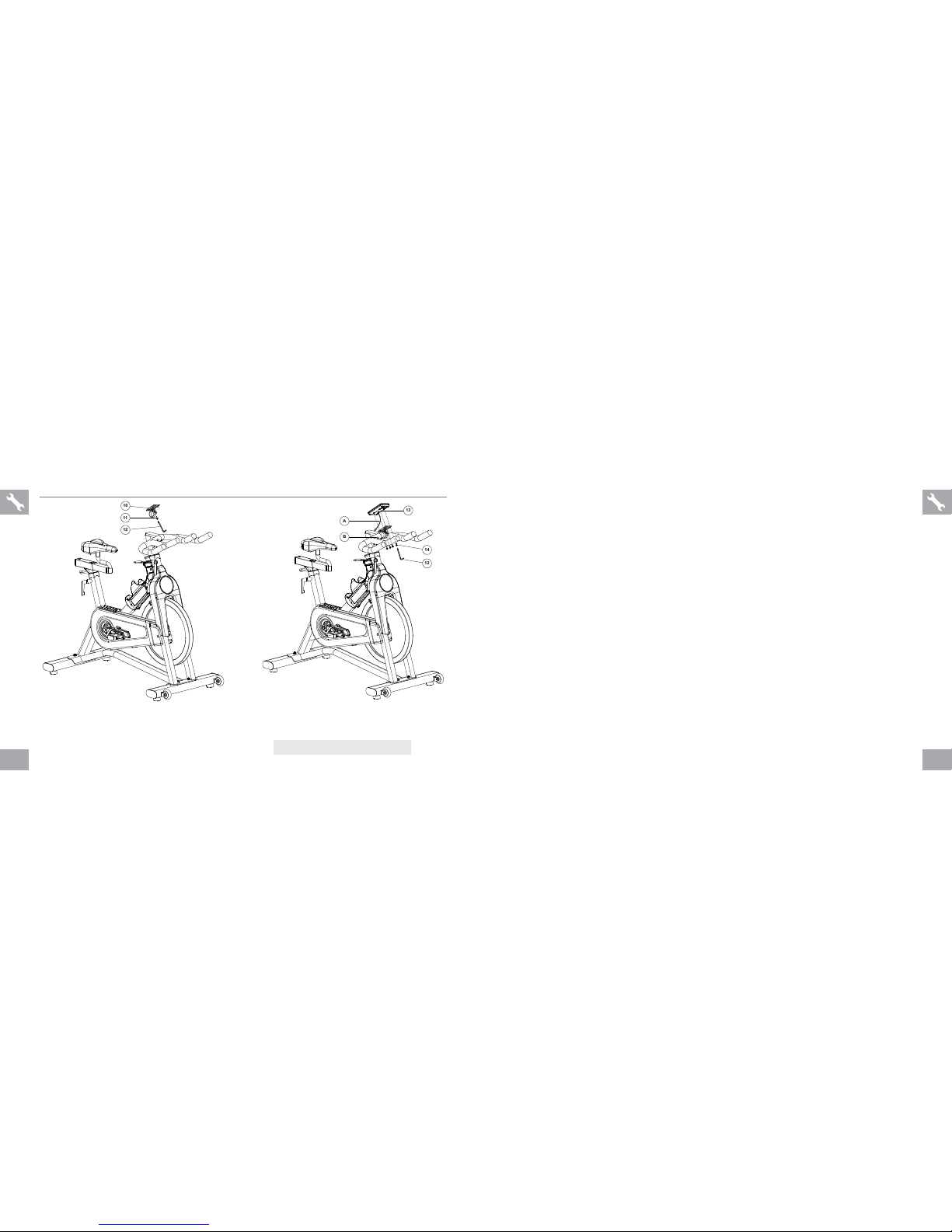
ASSEMBLY COMPLETE!
ASSEMBLY STEP 5 & 6
5 Attach the console bracket (10) to the handlebar using
1 screw (11), and secure firmly using the allen wrench
(12).
5 Attach the console (13) to the console bracket (10) using 4
screws (14), and secure firmly using the allen wrench (12).
Attach console cable (A) to console cable (B).
IC7.1/IC4000
Overall Dimension: 135.5 x 60.5 x 121 cm / 53" x 24" x 48"
Product Weight: 52 kg / 115 lbs
Max. User Weight: 136 kg / 300 lbs
121110
13
14
12
A
B
Page 6
1110
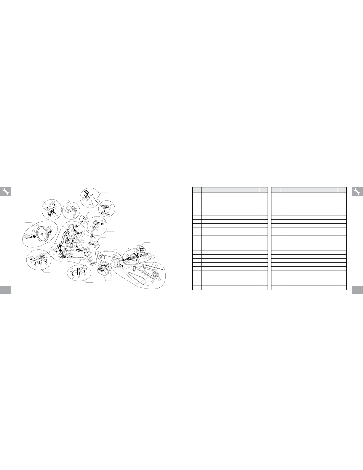
IC7.1/IC4000 EXPLODED VIEW IC7.1/IC4000 PART S LIST
3
33
3
34
56
32
70
1
2
8
9
7
10
3
4
3
3
5L
5R
6L
6R
8
9
3
32-2
11
12
13
14
17
15
16
16
13
15
17
14
18
21
22
23
22
62
19
20
31
16
15
17
13
14
18
36
38
35
37
21
21
62
62
22
68
22
22
22
68
64
67
65
66
67
22
67
67
22
66
65
69
39
40
41
42
43
32-1
40-1
40-2
40-2
40-1
28
27
29
30
25
26
25-1
28
24
45L
46-1
46-2
44L
52
45R
46
46-2
46-1
47
58
59
61
60
62
54
9
9
9
3
53
63
55
51
49
48
49
50
51
49
44R
A-01
A-02
A-03
A-04
A-05
A-06
A-06
A-08
A-07
A-09
A-10
A-12
A-12
A-11
A-13
18
27
57
8
NO. DESCRIPTION
QTY
A-01
FRAME ASSEMBLY
1
1
FRAME
1
2 STAINLESS STEEL PLATE 1
3 PHILLIP SCREW 8
4
SELF-TAPPING SCREW
1
5L
SWEAT GUARD ( L )
1
5R SWEAT GUARD ( R ) 1
6L FLYWHEEL DROPOUT PLATE ( L ) 1
6R
FLYWHEEL DROPOUT PLATE ( R )
1
7
ALLEN BOLT
2
8 END CAP 4
9 SELF-TAPPING SCREW 4
10
ANTI-SLIPPERY RUBBER PAD
2
11
SENSOR CLAMP
1
12 FRONT DECORATIVE COVER 1
13 QUICK RELEASE 2
14
QUICK-RELEASE NUT
2
15
QUICK-RELEASE RECEPTOR
2
16 QUICK-RELEASE SPRING 2
17 WASHER 2
18 SLEEVE 2
21 AL LEN B OLT 1
22 WASHER 2
23 EMERGENCY LEVELER 1
32-2 COMPUTER SENSOR WI RE SUPPORT 1
NO. DESCRIPTION
QTY
62
LOCK NUT
1
A-02
TENSION CONTROL KNOB SET
1
19 TENSION CONTROL KNOB 1
20 SPACER 1
A-03
HANDLEBAR SET
1
31
HANDLEBAR
1
A-04 SEAT PAD ADJUSTMENT SET 1
35 SEAT SLIDER 1
37
SADDLE
1
A-05
FLYWHEEL ASSEMBLY
1
32-1 MAGNET 1
39 FLYWHEEL 1
40
HUB SET
1
40-1
FLANGE NUT
2
40-2 WASHER Φ10*Φ21*2.0 2
41 HUB COVER 1
42
LOCKED RING
1
43
SMALL PULLEY
1
- FLYWHEEL DECAL 2
A-06 CRANK AXLE SET 1
45L CRA NK ( L ) 1
45R CRANK ( R ) 1
46 BOTTOM B RACKET 1
46-1 BB BOLT M8*20 2
46-2 CRANK CAP 2
Page 7
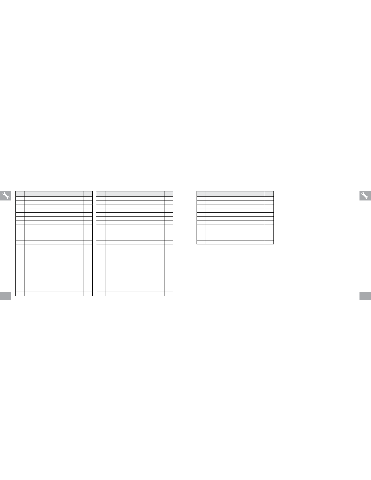
1312
NO. DESCRIPTION
QTY
A-12
PEDAL SET
1
44R
PEDAL ( R )
1
44L PEDAL ( L ) 1
A-13 BRAKE PAD ASSEMBLY 1
24
ACOUSTIC GROMMET
1
25
CALIPER
1
25-1 STOPPER 1
26 SQUARE NUT 1
27
WASHER
2
28
LOCK NUT
2
29 BRAKE SHOE SET( L ) 1
30 BRAKE SHOE SET( R ) 1
NO. DESCRIPTION
QTY
47
CRANK BOLT CAP
1
58
BIG PULLEY
1
59 ALLEN BOLT 2
60 ALLEN BOLT 6
61
SPRING WASHER
6
62
LOCK NUT
6
A-07 FRONT STABILIZER ASSEMBLY 1
21 ALLEN BOLT 2
22
WASHER
6
62
LOCK NUT
2
64 FRONT STABILIZER 1
65 CARRIAGE BOLT 2
66
CAP NUT
2
67
ADJUSTABLE LEVELER
2
68 TRANSPORTATION WHEEL BLACK 2
A-08 REAR STABILIZER ASSEMBLY 1
22
WASHER
2
65
CARRIAGE BOLT
2
66 CAP NUT 2
67 ADJUSTABLE LEVELER 2
69 REAR STABILIZER 1
A-09 COMPUTER ASSEMBLY 1
3 PHILLIP SCREW 4
32 COMPUTER 1
33 SENSOR FIX ER 1
NO. DESCRIPTION
QTY
34
SELF-TAPPING SCREW
1
56
COMPUTER SENSOR WIRE
1
70 COMPUTER WIRE 1
A-10 SEAT POST SET 1
13
QUICK RELEASE
1
14
QUICK-RELEASE NUT
1
15 QUICK-RELEASE RECEPTOR 1
16 QUICK-RELEASE SPRING 1
17
WASHER
1
18
SLEEVE
1
36 SEAT POST 1
38 END CAP (FOR SLIDER) 1
A-11
COVER SET
1
3
SELF-TAPPING SCREW
1
9 SELF-TAPPING SCREW 4
48 INNER CHAIN GUARD 1
49
WASHER
4
50
PHILLIP SCREW
2
51 PHILLIP SCREW 2
52 CHAIN GUARD SPACER 2
53 FRONT CHA IN GUARD BLACK 1
54 OUTER CHA IN GUARD 1
55 BE LT 1
57 PHILLIP SCREW 2
63 RUBBER STR IPPING 1
Page 8

Page 9

Elite IC7.1 / IC4000 Assembly Guide Rev. 1.0 | © 2014 Johnson Health Tech Made in China
Page 10

INFORMATION CARD HORIZON ELITE IC7.1 / IC4000
LIMITED HOME USE WARRANTY
EXCLUSIONS AND LIMITATIONS
Who IS covered:
• The original owner and is not transferable.
What IS covered:
• Repair or replacement of a defective motor, electronic component, or defective part and is the sole remedy of the warranty.
What IS NOT covered:
• Normal wear and tear, improper assembly or maintenance, or installation of parts or accessories not originally intended or compatible with the equipment as sold.
• Damage or failure due to accident, abuse, corrosion, discoloration of paint or plastic, neglect, theft, vandalism, re, ood, wind, lightning, freezing, or other natural
disasters of any kind, power reduction, uctuation or failure from whatever cause, unusual atmospheric conditions, collision, introduction of foreign objects into the
covered unit, or modications that are unauthorized or not recommended by the Manufacturer.
• Incidental or consequential damages. The Manufacturer is not responsible or liable for indirect, special or consequential damages, economic loss, loss of property,
or prots, loss of enjoyment or use, or other consequential damages of whatsoever nature in connection with the purchase, use, repair or maintenance of the equipment.
The Manufacturer does not provide monetary or other compensation for any such repairs or replacement parts costs, including but not limited to gym membership
fees, work time lost, diagnostic visits, maintenance visits or transportation.
• Equipment used for commercial purposes or any use other than a single family or Household, unless endorsed by the Manufacturer for coverage.
• Delivery, assembly, installation, setup for original or replacement units or labor or other costs associated with removal or replacement of the covered unit.
• Any attempt to repair this equipment creates a risk of injury. The Manufacturer is not responsible or liable for any damage, loss or liability arising from any personal
injury incurred during the course of, or as a result of any repair or attempted repair of your tness equipment by other than an authorized service technician. All repairs
attempted by you on your tness equipment are undertaken AT YOUR OWN RISK and the Manufacturer shall have no liability for any injury to the person or property
arising from such repairs.
HZ14_INFO_Elite_IC7.1_IC4000_Rev1_0 1-2
Page 11

INFORMATION CARD HORIZON ELITE IC7.1 / IC4000
LIMITED HOME USE WARRANTY
WEIGHT CAPACITY
300 lbs (136 kilograms)
ELECTRONICIAL & PARTS & DRIVE SET: 1.5 YEARS
Horizon warrants the electronic components, nish and all original parts for the
period specied above from the date of original purchase, so long as the device
remains in the possession of the original owner.
FRAME: 2 YEARS
Horizon warrants the frame against defects in workmanship and materials for
the period specified above from the date of original purchase, so long as the
device remains in the possession of the original owner. (The frame is defined
as the welded metal base of the unit and does not include any parts that can be
removed.)
WEAR ITEMS: 0.5 YEAR
Horizon warrants the wear items for the period specied above from the date of
original purchase, so long as the device remains in the possession of the original
owner.
CUSTOMER
TECH SUPPORT
If you have questions or if there are any missing parts, contact your local dealer.
Contact information may be located on the back pannel of your manual or on the warranty card.
Page 12

SAVE THESE INSTRUCTIONS
Read the OPERATION GUIDE before use. When using an electrical product, basic precautions should always be followed, including the following: Read all instructions before
using this bike. It is the responsibility of the owner to ensure that all users of this bike are adequately informed of all warnings and precautions. If you have any questions after
reading this guide, contact Customer Tech Support at the number listed on the back panel.
This bike is intended for in-home use only. Do not use this bike in any commercial, rental, school or institutional setting. Failure to comply will void the warranty.
• If you experience any kind of pain, including but not limited to chest pains, nausea, dizziness, or shortness of breath, stop exercising immediately and consult your physician
before continuing.
• When exercising, always maintain a comfortable pace.
• To maintain balance, it is recommended to keep a grip on the handlebars while exercising, mounting or dismounting the machine.
• Keep hands and feet clear at all times from moving parts to avoid injury. Never turn the pedal cranks by hand.
• Do not wear clothes that might catch on any part of the exercise bike.
• Do not use the exercise bike without proper footwear. NEVER operate the exercise bike with bare feet.
• Do not jump on the exercise bike.
• Do not dismount the exercise bike until the pedals are at a complete STOP.
• At no time should more than one person be on the exercise bike while in operation.
• This exercise bike should not be used by persons weighing more than the specied user capacity in the OWNER’S MANUAL WARRANTY SECTION . Failure to comply will
void the warranty.
• This exercise bike is intended for in-home use only. Do not use this exercise bike in any commercial, rental, school or institutional setting. Failure to comply will void the
warranty.
• The exerciser complies with the EN957-1/-5 standard, class of exerciser: HA; braking system is adjustable.
• Do not use exercise bike in any location that is not temperature controlled, such as but not limited to porches, pool rooms, bathrooms, car ports or outdoors. Failure to comply
will void the warranty.
• To prevent electrical shock, never drop or insert any object into any opening.
• Ensure that adjustment levers (seat and handlebar fore-and-aft) are properly secured and do not interfere with range of motion during exercise.
WARNING (CI7.1 / IC4000 MODELS)
Page 13

TO REDUCE THE RISK OF BURNS, FIRE, ELECTRICAL SHOCK OR INJURY TO PERSONS:
• Do not use other attachments that are not recommended by the manufacturer. Attachments may cause injury.
• Do not operate where aerosol (spray) products are being used or when oxygen is being administered.
• Use the exercise bike only as described in the exercise bike guide and owner’s manual.
• Disconnect all power before servicing or moving the equipment. To clean, wipe surfaces down with soap and slightly damp cloth only; never use solvents.
(See MAINTENANCE)
• Do not operate under blanket or pillow. Excessive heating can occur and cause re, electric shock, or injury to persons.
• At NO time should children under the age of 13 or pets be within 3m /10 feet of the machine.
• At NO time should children under the age of 13 use the exercise bike.
• Children over the age of 13 or disabled persons should not use the exercise bike without adult supervision.
• Never operate the exercise bike if it has a damaged cord or plug, if it is not working properly, if it has been dropped or damaged, or immersed in water. Return the exercise
bike to a service center for examination and repair.
• Do not remove the console covers unless instructed by Your local dealer. Service should only be done by an authorized service technician.
WARNING (CI7.1 / IC4000 MODELS)
It is essential that your exercise bike is used only indoors, in a climate controlled room. If your exercise bike has been exposed to colder temperatures or high moisture
climates, it is strongly recommended that the exercise bike is warmed up to room temperature before rst time use. Failure to do so may cause premature electronic failure.
HZ14_INFO_Elite_IC7.1_IC4000_Rev1_0 1-2
Page 14

OPERATION GUIDE
IC7.1/IC4000
Page 15

32
INDOOR CYCLE OPERATION
Page 16

54
A
H
I
B
CD
A
F
G
E
MODEL INFORMATION
A) ADJUSTABLE LEVERS: allow adjustment to the height of both saddle post & handlebar
NOTE: To reposition the lever, pull lever outward and turn.
B) HEAVY FLYWHEEL: high-inertia flywheel creates a smooth feel
C) TRANSPORTATION WHEEL: allows for easy movement of the machine
D) BELT DRIVE: simulates the feel of road riding
E) CRANK: initiates movement to the flywheel
F) SADDLE POST: allows vertical adjustment to customize height for any user
G) SADDLE SLIDER: allows fore/aft adjustment to customize for any user
H) SADDLE: extra padding to provide a comfortable ride
I) TENSION CONTROL & EMERGENCY BRAKE LEVER: friction brake with micro-
adjustable knob and push-down emergency stop
NOTE: In case of emergency, press the emergency brake lever down to bring the
flywheel to an abrupt stop.
Page 17

76
HOW TO ADJUST THE INDOOR CYCLE
The Indoor Cycle can be adjusted for maximum comfort and exercise effectiveness. The instructions below describe one
approach to adjusting the Indoor Cycle to ensure optimal user comfort and ideal body positioning; you may choose to adjust the
Indoor Cycle differently.
SADDLE ADJUSTMENT
Proper saddle height helps ensure maximum
exercise efficiency and comfort, while
reducing the risk of injury. Adjust the saddle
height to make sure it’s in proper position, one
that keeps a slightly bend in your knee while
your legs are in the extended position.
HANDLEBAR ADJUSTMENT
Proper position for the handlebar is based
primarily on comfort. Typically, the handlebar
should be positioned slightly higher than
the saddle for beginning cyclists. Advanced
cyclists could try different heights to get the
arrangement most suitable for you.
B
A
HOW TO MOVE THE INDOOR CYCLE
Due to the weight of the Indoor Cycle, it is recommended
that two persons move it. While one person lifts the back
of the indoor cycle, the second person firmly holds the
handlebar and tips the indoor cycle forward until it rolls
on the wheels. Carefully move the Indoor Cycle to the
desired location and then lower it.
If the Indoor Cycle rocks on the floor after being set
down, turn the leveling feet underneath the front or rear
stabilizer until the rocking motion is eliminated.
Leveling Feet
To reduce the risk of injury, use extreme caution
while moving the indoor cycle. Do not attempt to
move it over uneven surfaces and make sure there’s
a safety space of 20 inch (minimum) to the nearest
equipment is recommended.
WARNI NG
LOCATION OF THE
INDOOR CYCLE
Place the Indoor Cycle on a
level surface. There should be
6 feet (183 cm) of clearance
behind the Indoor Cycle, 3 feet
(91 cm) on each side and 1 foot
(30 cm) in front of the Indoor
Cycle. Do not place the cycle
in any area that will block any
vent or air openings. The Indoor
Cycle should not be located in
a garage, covered patio, near
water or outdoors.
3 ft
6 ft
3 ft
91 cm 91 cm
1 ft
183 cm
30 cm
FRONT
REAR
BIKE
Page 18

98
TO ADJUST THE
SADDLE HEIGHT:
Rotate the adjustment lever
counterclockwise and adjust the
saddle to a comfortable pedaling
position. Rotate the lever clockwise
to lock saddle position.
TO ADJUST THE
SADDLE HORI ZONTAL
POSITION:
Rotate the adjustment lever
counterclockwise to slide the saddle
forward or backward as desired.
Rotate the lever clockwise to lock
saddle position. Test the saddle slide
for proper operation.
Do not adjust the
saddle position
beyond the stop
marks on the
saddle slider
Do not adjust
saddle height
beyond the
stop mark on
the stem
TO ADJUST THE
HANDLEBAR HEIGHT:
Rotate the adjustment lever
counterclockwise to adjust the handlebar
height. Raise or lower the handlebar
to the desired height. Rotate the lever
clockwise to lock handlebar position.
TO ADJUST THE PEDAL
STRAPS:
Place each foot ankle on the pedal
and in the toe clip that the foot ankle is
centered over the pedal spindle (center
of the pedal). Rotate one foot to arms
reach and pull up on the toe clip strap.
Repeat for the other foot. Keep your
knees over your feet as you pedal.
To remove your foot from the toe clip,
loosen the strap and pull out.
Do not adjust the
handlebar height
beyond the stop
mark on the stem
The pedal
straps should be
adjusted to hold
the foot snugly in
the pedal
Page 19

11
TENSION CONTROL AND EMERGENCY BRAKE
The preferred level of difficulty in pedaling (resistance) can be regulated in fine increments by use of the tension control
knob. To increase the resistance, turn the tension control knob clockwise. To decrease the resistance, turn the knob
counter clockwise.
IMPORTANT:
• To stop the flywheel while pedaling, push down on the red
emergency brake lever.
• The flywheel should quickly come to a complete stop.
• Make sure your shoes are fixed into the toe clip.
• Apply full resistance load when the bike is not in use to
prevent injuries due to moving drive gear components.
Tension control knob
Emergency brake
The Indoor Cycle does not have a free moving flywheel; the
pedals will continue to move together with the flywheel until
the flywheel stops. Reducing speed in a controlled manner
is required. To stop the flywheel immediately, push down
the red emergency brake lever. Always pedal in a controlled
manner and adjust your desired cadence according to your
own abilities. Push the red lever down = emergency stop.
WARNI NG
The Indoor Cycle uses a fixed flywheel that builds momentum and will keep the pedals turning even after the user stops pedaling or if
the user’s feet slip off. DO NOT ATTEMPT TO REMOVE YOUR FEET FROM THE PEDALS OR DISMOUNT THE MACHINE UNTIL
BOTH THE PEDALS AND THE FLYWHEEL HAVE COMPLETELY STOPPED. Failure to follow these instructions may lead to loss of
control and the potential for serious injury.
WARNI NG
CONSOLE OPERATION
BUTTONS
MODE/RESET To confirm all settings. Press this button and hold for 2 seconds to reset all function figures.
SET To set up the value of TIME, DISTANCE, CALORIES, PULSE. You can hold the button to increase the
value fast. (The computer has to be in stop condition.)
FUNCTIONS
SCAN Displays all function TIME→DISTANCE→CALORIES→ PULSE→ RPM/SPEED in sequence.
RPM Displays the pedaling Rotation Per Minute. The RPM and SPEED will switch to another display in every
6 seconds after exercise starts.
SPEED Displays the user’s exercise speed.
TIME 1. You can press “SET” button to set target time between 0:00 to 99:00 for count down function.
2. It can be set up by the user or accumulated automatically for count up function.
DISTANCE 1. Your can press “SET” button to set target distance between 0:00 to 99:50 for count down function.
2. It can be set up by the user or accumulated automatically for count up function.
CALORIES 1. You can press “SET” button to set target calories between 0 to 9990 for count down function.
2. It can be set up by the user or accumulated automatically for count up function.
PULSE Displays the user’s pulse. User may set the target pulse. When pulse value reaches to the target, the
computer will alarm with “Beep” sound.
WIRELESS HEART RATE
This bike includes a Polar® wireless heart rate strap and has a built-in wireless heart rate receiver. When used in conjunction
with a wireless chest transmitter, your heart rate can be transmitted wirelessly to the console.
Prior to wearing the wireless chest transmitter on your chest, moisten the two rubber electrodes with water. Center the chest
strap just below the breast or pectoral muscles, directly over your sternum, with the logo facing out. NOTE: The chest strap
must be tight and properly placed to receive an accurate and consistent readout. If the chest strap is too loose, or positioned
improperly, you may receive an erratic or inconsistent heart rate readout.
Page 20

1312
TROUBLESHOOTING
& MAINTENANCE
CONSOLE OPERATION
1) After installing the battery (CR2032 3V), the display will turn on (Fig. A) and
the console will make a beep sound before entering TIME and DATE setup.
Press “MODE” button to confirm. When complete, the console will display
the main screen (Fig. B).
2) Press "SET" to enter set-up mode. Press “SET” button to adjust the TIME
value and press “MODE” to confirm setting. Repeat the process to set up
DISTANCE, CALORIES and PULSE.
3) During your workout, TIME, DISTANCE, and CALORIES will count up
from 0. If you have set a TIME, DISTANCE or CALORIES TARGET, the
console will count down from the target you have set to 0. When you are
within 30 seconds of completing your target, the console beeps. If you keep
exercising after reaching your target, the console will count up from 0. When
a pulse signal is detected, the console will beep consistently.
4) Press "SCAN" during your workout and the display will change the feedback
every 6 seconds (Fig. C).
5) Press “MODE” during your workout and the display will only show RPM and
SPEED. The console will cycle between RPM and SPEED every 6 seconds.
NOTE:
• After 4 minutes of inactivity, the console will display TEMPERATURE and TIME
and DATE (Fig. D). Press any button to return to the main screen (Fig. B).
• Removing battery will restore default settings.
• If the computer displays abnormally, re-install the battery.
• Battery Spec: 3V CR2032 (1PC).
• To replace the battery, remove the screw and the battery cover on the back of
the console.
Fig. A Fig. B
Fig. C Fig. D
Heart rate monitoring systems may be inaccurate. Over exercise may result in series
injury or death. If you feel faint, stop training immediately.
WARNI NG
Page 21

1514
TROUBLESHOOTING
PROBLEM: The Indoor Cycle makes a squeaking or chirping noise.
SOLUTION: Verify the following:
• The Indoor Cycle is on a level surface.
• Loosen all bolts attached during the assembly process, grease the threads, and tighten again.
COMMON PRODUCT QUESTIONS
ARE THE SOUNDS MY INDOOR CYCLE MAKES NORMAL?
Our Indoor Cycles are some of the quietest available because they use belt drives and cantilever brake resistance. We
use the highest grade bearings and chains/belts to minimize noise. However, because the resistance system itself is
so quiet, you will occasionally hear other slight mechanical noises. Unlike older, louder technologies, there are no fans,
friction belts, or alternator noises to mask these sounds on our Indoor Cycles. These mechanical noises, which may or
may not be intermittent, are normal and are caused by the transfer of significant amounts of energy to a rapidly spinning
flywheel. All bearings, chains/belts and other rotating parts will generate some noise which will transmit through the
casing and frame. It is also normal for these sounds to change slightly during a workout and over time because of thermal
expansion of the parts.
WHY IS THE INDOOR CYCLE I HAD DELIVERED LOUDER THAN THE ONE AT THE STORE?
All fitness products seem quieter in a large store showroom because there is generally more background noise than in
your home. Also, there will be less reverberation on a carpeted concrete floor than on a wood overlay floor. Sometimes a
heavy rubber mat will help reduce reverberation through the floor. If a fitness product is placed close to a wall, there will
be more reflected noise.
HOW LONG WILL THE BELT LAST?
The computer modeling we have done indicated virtually thousands of maintenance free hours. You should not have to
replace the belt as long as you have the Indoor Cycle.
CAN I MOVE THE INDOOR CYCLE EASILY ONCE IT IS ASSEMBLED?
Your Indoor Cycle has a pair of transport wheels built into the front stabilizer tube. Please follow the MOVING THE
INDOOR CYCLE section to transport your Indoor Cycle. It is important that you place your Indoor Cycle in a comfortable
and inviting room. Your Indoor Cycle is designed to use minimal floor space. Many people will place their Indoor Cycles
facing the TV or a picture window. If at all possible, avoid putting your Indoor Cycle in an unfinished basement. To make
exercise a desirable daily activity for you, the Indoor Cycle should be in a comfortable setting.
In order for Customer Tech Support to service your Indoor Cycle they may need to ask detailed questions about
the symptoms that are occurring. Some troubleshooting questions that may be asked are:
• How long has this problem been occurring?
• Does this problem occur with every use? With every user?
• If you are hearing a noise, does it come from the front or the back? What kind of noise is it (thumping,
grinding, squeaking, chirping etc.)?
• Has the machine been lubricated and maintained per the MAINTENANCE schedule?
Answering these and other questions will give the technicians the ability to send proper replacement parts and
the service necessary to get you and your Indoor Cycle running again!
If this does not remedy the problem, you may
CONTACT CUSTOMER TECH SUPPORT AT THE NUMBER ON THE INFORMATION CARD.
The following information may be asked of you when you call. Please have these items readily available:
• Model Name
• Serial Number
• Proof of Purchase (receipt or credit card statement)
You may find more troubleshooting suggestions on the customer support section of our website. Contact
customer support using the contact information on the INFORMATION CARD.
Page 22

16
MAINTENANCE
The safety level given by the design of the Indoor Cycle can only be maintained when the equipment is regularly examined
for damage and wear. Inoperable components should be replaced or the equipment should be put out of use until it is
repaired.
DAILY
• Wipe down the Indoor Cycle after each use to remove sweat and moisture. Use soap and water, or a diluted non-abrasive
domestic cleaner solution. Rinse to remove detergent residue and then dry off.
• Before each session, inspect for loose components such as pedals or cranks prior to commencing the next use. Tighten
up any loose parts.
WEEKLY
• Check for proper flywheel alignment. Torque flywheel nuts as necessary.
• Remove chain guard and check for loose chain. Adjust and lubricate the chain as necessary.
• Check to make sure the crank arms are tight to the bottom bracket.
• Inspect all parts, nuts, bolts, or screws for adjustments, replacements or maintenance.
MONTHLY
• Inspect the frame and main assembly components for rust or corrosion. Tilt the cycle or place in an upside down position
to locate areas where rust and corrosion may develop. Use a small, wire brush to remove rust build-up in small crevasses,
such as leveling feet, quick release levers and other bolt assemblies.
• Inspect all wear items for adjustments or possible part replacement. Give particular attention to the following:
A) Inspect brake pad for wear. Excessive wear or dryness indicates replacement is required.
B) Inspect seat pad for wear. Rips, tears or excessive movement indicates replacement is required.
C) Inspect pedals for play. Excessive movement of pedals indicates replacement is required.
• Inspect the chain for tensioning by rotating the crank to drive the flywheel forward. Do this motion in 1/4 turns to assess if
there is free play between the crank and the flywheel.
• Dryness or prolonged use may cause the height and reach adjustments for the seat and handlebar to become tight. If this
is the case, the sliding assembly should be removed from the frame and have a smear of light duty grease applied along
the sliding surface before assembly. Similarly, apply some light grease to the clamping assembly to ensure it does not
seize up. Clean off excessive grease before reassembly.
• Please lubricate the seat post, brake pad and handlebar adjustment regularly with lubricant in your parts package.
D: Entsorgungshinweis
VISION Fitness / HORIZON Fitness / TEMPO Fitness / TREO Fitness / LIVESTRONG Fitness- Produkte sind
recyclebar. Führen Sie das Gerät am Ende der Nutzungsdauer einer sachgerechten Entsorgung zu (örtliche
Sammelstelle).
GB: Waste Disposal
VISION Fitness / HORIZON Fitness / TEMPO Fitness / TREO Fitness / LIVESTRONG Fitness products are
recyclable.
At the end if its useful life please dispose of this article correctly and safely (local refuse sites).
F: Remarque relative à la gestion des dèchets
Les produits VISION Fitness / HORIZON Fitness / TEMPO Fitness / TREO Fitness / LIVESTRONG Fitness
sont recyclables. A la fin sa durrèe d`utilisation, remettez I´appareil à un centre de gestion de dèchets correct
(collecte locale).
NL: Verwijderingsaanwijzing
VISION Fitness / HORIZON Fitness / TEMPO Fitness / TREO Fitness / LIVESTRONG Fitness producten zijn
recycleerbaar. Breng het apparaat aan het einde van de gebruiksduur naar een op recycling gespecialiseerd
bedrijf (plaatselijk verzamelpunt).
E: Informaciones para la evacuaciòn
Los productos de VISION Fitness / HORIZON Fitness / TEMPO Fitness / TREO Fitness / LIVESTRONG Fitness
son riciclables. Cuando se termina la vida ùtil de un aparato o una màquina, entrèguelos an una impresa local
de eleiminaciòn de residuos para su reciclaje.
I: Indicazione sullo smaltimento
I prodotti VISION Fitness / HORIZON Fitness / TEMPO Fitness / TREO Fitness / LIVESTRONG Fitness sono
reciclabill. Quando I`apparecchio non servirà più, portatelo in un apposito punto di raccolta della Vostra città
(Punti di raccolta comunall).
PL: Wskazòwka dotyczàca usuwania odpadòw.
Producty firmy VISION Fitness / HORIZON Fitness / TEMPO Fitness / TREO Fitness / LIVESTRONG Fitness
podlegajà recyklingowi. Pod koniec okresu o`ywalnoÈcl pros`z oddac urzàdzenie do wlaÈciwego punkto
usuwania odpadòw (lokalny punkt zbiorczy).
Page 23

Elite IC7.1 / IC4000 Operation Guide Rev. 1.1 | © 2014 Johnson Health Tech Made in China
 Loading...