

Page 1
elinca sa switzerland www.elinchrom.com
POWERPOWER
POWER
POWERPOWER
UNIVERSALITYUNIVERSALITY
UNIVERSALITY
UNIVERSALITYUNIVERSALITY
Digital 3000 AS
For DIGITAL PHOTOGRAPHYFor DIGITAL PHOTOGRAPHY
For DIGITAL PHOTOGRAPHY
For DIGITAL PHOTOGRAPHYFor DIGITAL PHOTOGRAPHY
TOTAL
ASYMMETRYASYMMETRY
ASYMMETRY
ASYMMETRYASYMMETRY
Instructions for useInstructions for use
Instructions for use
Instructions for useInstructions for use
110V and 230V, Version
English
Page 2

Table of contentsTable of contents
Table of contents
Table of contentsTable of contents
page
Safety notice
Control panel
Before you start
Technical data
Mains inlet and fuses
Open flash button
Power variator
Troubleshooting
Photo-cell
Synchronization
Audible signal
Modelling lamp selector
IRS remote control
Lampheads
Other poducts
" accessories overview"
33
3
33
44
4
44
55
5
55
66
6
66
77
7
77
88
8
88
99
9
99
99
9
99
1010
10
1010
1010
10
1010
1010
10
1010
1111
11
1111
1111
11
1111
12-13-1412-13-14
12-13-14
12-13-1412-13-14
1515
15
1515
P.S: Technical data subject to change.
The listed values are guide values which may vary due to tolerances in components used.
2
Page 3

The Elinchrom Digital generator is manufactured by Elinca S.A. CH -1020 Renens/Switzerland
Dear Photographer,
Thank you for buying your «Digital 3000 AS» flash generator.
All Elinchrom products are manufactured using the most advanced technology. Carefully
selected component are used to ensure the highest quality and the equipment is submitted
to many controls both during and after manufacture.
We trust that it will give you many years of reliable service.
All flash units are manufactured for the studio and location use of professional
photographers.
Only by observance of the information given, can you secure your warranty, prevent
possible damage and increase the life of this equipment.
SAFETY NOTICE
According to safety regulations, we draw your attention to the fact that these
electronic flash units are not designed for use outdoors, in damp or dusty conditions and
should not be used after being exposed to sudden temperature changes causing condensation. They must always be connected to an earthed (grounded) mains supply.
On no account should any objet be inserted into the ventilation holes.
The units may retain an internal charge for a considerable time even though disconnected
from the power supply.
!!
!
!!
FLASH SYSTEMS STORE ELECTRICAL ENERGY IN CAPACITORS BY APPLYING HIGH VOLTAGE.
FOR YOUR SAFETY, NEVER OPEN YOUR FLASHES.
ONLY AN AUTHORISED SERVICE ENGINEER SHOULD OPEN OR ATTEMPT TO REPAIR THE UNITS.
FOR REPAIRS, BRING THEM TO YOUR ELINCHROM AGENT.
3
Page 4
120125721
10
9 11
17
18
2
3
4
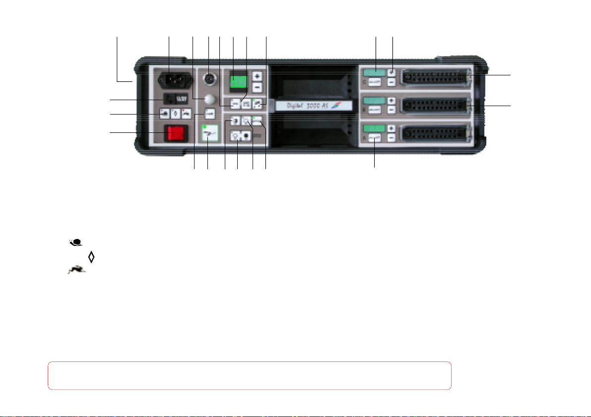
CONTROL PANEL
1. Mains inlet power socket
2. Mains fuse (16 AT, slow blow)
3. Charge speed selectors
- slow charge
- normal charge
- fast charge
4. Mains switch
5. Photocell and IR-Receiver
6. Photocell on/off
7. Sync.-socket with security lock
8. Open flash with charge indicator
9. IR-Remote On/off
FOR YOUR SAFETY, NEVER OPEN YOUR POWER PACKS OR YOUR LAMPHEADS.
FOR REPAIRS, BRING THEM TO YOUR ELINCHROM AGENT
4
19
6
15 16
10. LED indication of total power
11. Generator selector IR (1-8 packs)
12. Multi-purpose accoustic signal
13. Half/full power for modelling lamps
14. Modelling lamps on/off
15. Modelling lamp dimmer/charge signal
16. Proportional modelling light
17. Power output indication in Ws/joules
18. Lamphead sockets
19. Security catches
20. Lamphead power modulators
21. Socket accessories
22. Lamphead on/off
14
13
8
22
..
.
..
Page 5

Operating instructions
1)
Mains connection
The unit is manufactured to run on 200-240 V, 50/60 Hz. Before connecting them for the first
time, make sure that your mains supply and the rating set on the equipment (electrical
specification plate) are compatible.
2)
Check that the mains switch (4) is OFF
3)
Insert mains cable to the MAINS INLET (1) and connect to a FULLY EARTHED OUTLET
4) Using the mains switch (4) and switch the unit ON (switch illuminated)
Connect lampheads ensuring that lampheads switches (22) are OFF, i.e. display NOT illuminated
5)
6)
Select charging rate (3) "normal"
7)
Select modelling lamp setting (16)
8)
Connect the synchro cord on the socket (7)
9)
Check that photocell (6) is OFF (not illuminated)
10)
Switch on the lampheads : the touch ( 22) switches individually the flash circuits and modelling lamps
11)
Select the power with the touch (+ or -).
12)
The green open flash button ( 8) will light up, indicating that the unit is ready for operation.
According to the safety regulation: we draw your attention to the fact that this
equipment should be used only in a dry environment; it must be protected from
dripping water and from extremely dusty conditions. The unit must ALWAYS be
plugged into an EARTHED electrical socket.
5
Page 6

TECHNICAL DATA :
This power pack Digital 3000 AS ( 3000Ws) offers three asymmetrical power head outlets.
The power levels are indicated in Ws by bright LED display. These displays may be individually varied
in 1/10th f-stop to any one of 57 settings on each lamphead (with three lampheads).
The variation is continuous on 6.6 f-stops, (diaphram variation 22.7 to 180.3).
POWER REQUIREMENTS :
For version 110/120 V : Mains voltage: 110-140 Vac 50/60 Hz
For version 220/230 V : Mains voltage: 210-240 Vac/50 Hz
Dimensions: 49 x 14 x 32 cms
Weight: 11.65 kg
CHARGE SPEED
on mains 230 V- 50 Hz 1.8 - 10 s 0.8 - 4.5 s 0.7 - 3.5 s
on mains 115 V- 60 Hz 2 - 11s 0.9 - 5.5s 0.8 - 4.5 s
RELATION OF POWER RANGE BETWEEN THE OUTLETS
Guide aperture is based on the "Digital S" head and the standard reflector, distance 1 m/3.3 ft
and film ISO 100/21 DIN.
Display Ws f-stop Power
9 3000 (180.3) 1/1
8 1500 (128.3) 1/2
7 750 (90.3) 1/4
6 375 (64.3) 1/8
5 188 (45.3) 1/16
5** 95 (32.3) 1/32 with 2 lampheads
5*** 62 (22.7) 1/48 with 3 lampheads
*with 2 or 3 lampheads
6
Page 7

1. MAINS SUPPLY
While the MAINS SWITCH (4) is switched off firmly push in the plug of the
original ELINCHROM mains cord into the socket (1).
2. FUSE
Standard type 5 x 20 mm, 16 AT (tempered). Before exchanging a blown fuse, switch off the unit and
remove mains cable. Depress and turn the fuse holder anti-clockwise 1/8th and remove it.
If the new fuse blows immediately upon reconnection return the pack to an ELINCHROM service
centre for a check-up. (N.B. Check correct value of the fuse : 16 AT).
N.B. SECURITY FUSE
This unit is protected by an internal security device. Should the unit not work properly, for example
because of a defective power component, the internal security fuse of 16AF (fast) would instantly get
destroyed, which avoids any recharging. From then on, the power pack requires a check up by a
technical Elinchrom service.
3. MAINS SWITCH
The button lights up when the pack is switched on. Switch off before removing the mains cord.
Note : the absence of charge, despite the switch being illuminated, indicates a fault.
4. CHARGE SPEED SELECTOR
Select the required charging speed with the selector (3).
FAST : is the standard position recycling, for use in the professional studio.
(Position for the digital "one shot")
230 V = 16 A 115 V = 25 A
NORMAL : standard recycling recommended for use in the studio with line 16 A.
(Position for the digital "multi-shot")
230 V = 12 A 115 V = 20 A
charge
SLOW : position is recommended when the mains capacity is too limited for the use with
the standard charge. (for the digital "multi-shot")
230 V = 8 A 115 V = 15 A
7
Page 8

N.B. For even less load on the power supply line use and jointly. The modelling
lamps automatically extinguish when the generator is charging but illuminate
when the charge cycle ends.
5. INITIAL CHARGE
If the generator has been recently used and the capacitors do not require «reforming», the
generator will charge at the speed setting indicated, i.e. fast, normal or slow.
If the generator has been recently used , to reform the capacitors it will charge slowly. If the desired
speed setting is fast or normal, the appropriate indicator will glow, but the slow charge indicator will
blink to show that for this one charge sequence it has automatically taken control.
6. OPEN FLASH «TEST»
Having pressed this button release a flash, the green led «READY» light will appear again once the
unit is recharged. If the green light does not appear the charge system could by defective.
Please contact and send to an authorized Elinchrom service.
N.B. Situation 2, as above is the only time when the open flash will function while the indicator blinks.
At other times, the generator is not ready (still charging or fed with incorrect requests) and will
therefore not function.
NOTE :
The "Digital" unit have an integrated discharge system, protected by a thermic switch.
In order to restrict the heating of the unit, we suggest to release a flash with the green button (8)
"READY" after each strong reduction of power (more than 2f-stop).
This allows to release the excess of energy in the flash tube. You will gain time and extend the life
span of your power packs.
7. AUDIBLE RECHARGE SIGNAL
When the indicator of the
accepted by the generator (useful when using the IR handset).
There is an audible signal after each recharge. It indicates that the generator is ready.
Continuous signalling indicates a false request or malfunction.
Please check generator and lamphead connections.
touch (12) is illuminated and will sound whenever a command has been
8
Page 9

8. TOTAL POWER
This display indicates the total power released through the lampheads.
The variation is a single steps or if the touch is held it will run continuously.
The first number indicates charges by full f-stop, the second number by 1/10 f-stop.
When the total power is increased each individual lamphead increases proportionately.
The ratio never changes and the power in any one lamphead is limited only by the total power
in the generator.
When this power is reduced your chosen asymmetry remains, but is always variable at your
discretion.
9. INDIVIDUAL POWER OUTPUT
This facility gives subtlety and independence of power control unobtainable in any other way.
The Ws/Joules readout enables you at a glance to evaluate the relative power of each lamphead
which you may change at any time. It varies progressively with the principal power read-out.
The limite are only the maximum power of the pack and the minimum power through one outlet - all
steps being in 1/10th f-stops.
10. POWER INDICATOR «BLINKS»
If the power display blinks, the connecting of the lamphead may have given a total Ws/Joules
display of all lampheads of more power than the generator can store.
Press the touch to reduce the totals of the power displayed to the correct figure. Alternatively,
switch off a lamphead.
Conversely, if at minimum power, a lamphead is disconnected, the power indicator will blink
because there is now more power in the generator than the read-outs in Ws/Joules indicate. Adjust
by pressing .
N.B. The display will also blink if lamphead power supply is greater than the flashtube can accept, e.g. an
S1500N head fitted to a generator outlet displaying 3000 Ws will not release and the display indicates that there
is an incorrect request.
Adding or removing a lamphead does not change the power programmed into other lampheads. It increases
or decreases the total power stored.
-
+
9
Page 10

11. SWITCHABLE PHOTOCELL (SLAVE)
When switched ON indicator illuminated, the pack can be remotely triggered by another flash unit in
your studio.
In difficult situations e.g. daylight, blinding or obstacles, the additional cell (code 11080) with 5 m
cord (extensions available) solves most problems.
Alternatively use the FRC-SYNCRON (code 19316) cordless remote flash release.
12. SYNCHRONISATION SOCKET
The Amphenol secure locking system with standard 5 m cable is retained.
Longer cables may be used.
N.B. Do not link ELINCHROM units by cable to other manufacturers sync outlets.
ELINCHROM uses low voltage (12 V) for security reasons and other systems with higher voltages
may cause damage.
12. ACCESSORY SOCKET
Alternatively the ELINCHROM SYNCRON
(code 19316)
radio may be used with the FRC-1 transmitter (code 19306) which
releases the flash instantaneously - faster but slightly slower than
by sync cable. Therefore, use 1/60th for focal plane shutters and
1/125th for in lens shutters.
Alternatively mount an infrared flash trigger on the camera
(e. g. Prolinca IR transmitter : code 40203)
10
, cordless
Syncron Set : 19310
FRC1 : 19306
Page 11

14. MODELLING LAMP CONTROLS
The modelling lamp will only function when the lamphead is switched on (note : there is an
overheating control switch ON/OFF in the lamphead).
- Simple ON/OFF with ON setting indicated. Also incorporated is a slow start system to
prolong lamp life
- Half power lamp setting further extends lamp life
- Adjusts the lamp to vary with the flash power.
- DIM/BRIGHT CHARGE INDICATOR This setting underpowers the modelling lamps during
charging. At full charge they <<indicate>> by coming to full brightness.
- Used together, the modelling lamp extinguishes during charge.
15. USE OF IRS
To activate the Infra Red System press the IRS Control
Allocate the unit a channel number. First press the channel selector
This will display a channel number 0 - 8. keept this button pressed and when you have reached your
chosen number release. This sets the unit to the channel number displayed.
You can either select a different number for every head. If you wish to control two or more heads
identically then give them the same channel number, they will then respond to the same signal.
If any other number is selected on the IR-handset, the IRS indicator will blink to advise
that the generator is not accepting the commands.
To use the IR-remote :
first select a numbered channel on the handset.
This will activate the unit(s) allocated to that channel. No other units will respond. To measure the
f-stop, this unit can be flashed alone OR, to take an overall reading, ALL units will respond if «O»
is pressed on the handset.
IR Remote control
code : 19319
11
Page 12

USE OF IRS
The indicator on the IRS will «blink» on the generator when its channel has not been selected.
However, selecting its channel «O» will re-activate the units response system.
The units function like and are therefore totally compatible with Micro AS power packs and 750 Micro.
13. LAMPHEADS
Important :
When plugging in a lamphead connector, first push in the front part, then firmly press in the
whole plug, the rear part being secured by the locking spring.
DO NOT PLUG IN OR UNPLUG LAMPCORDS WHILE THE DISPLAYS ARE ON i.e. ILLUMINATED.
14. LAMPHEADS ON/OFF
22
2
22
11
1
11
Connect the lamphead. The ventilator fan functions even in OFF mode.
After a studio session, leaving the generator switched on, but the lampheads OFF extends lamp
and tube life
If the power display does not illuminate i.e. ON/OFF appears not to function, the lamphead is
incorrectly fitted, the connector is damaged or it is an old lamphead unadapted.
15. FUSES FOR LAMPHEADS
Use only FAST BLOW FUSES, type 5 x 20 mm corresponding to the label
on each lamphead.
Different modelling lamps require corresponding fuses.
Slow blow fuses will not protect the modelling lamp.
The fast blow fuse will protect the triac of the modelling lamp
circuit, the lamp and therefore the flash tube.
.
FUSE
W 110V 240V
200 2AF 2AF
300 5AF 2,5AF
650 10AF 5AF
ATTENTION
use only
recommanded fuse
12
Modelling
switch
3 0 0 0
Fuse
+
-
Page 13

16. PROTECTIVE PIREX DOME
For use with standard halogen lamp GX 6.35 socket.
Transparent, matt or yellow (400° K colour correction), can be fitted to all lampheads,
except R heads (rectangular heads) for which clear or matt security filters are available.
Easy attachment of the protective dome:
- Disconnect the lamphead from the pack
- Loosen the 3 screws of the lamphead reflector
- Fit the clips underneath the screw heads and tighten the screws
- Put the dome in place and hook the springs into the airvent holes.
The security filters for the Digital RE - R 3000 - Mini R, can be put on the lateral accessory holders,
clear (code 26253) or matt (code 26254).
17. LAMPHEAD TYPES
1. With standard flash duration : Types S and R (Digital S - Digital SE - Digital RE)
2. With action stopping (short flash duration) : Type A (X 6000N and Twin X4 with one power pack)
For fashion photography, sport applications and just as useful in the studio for
photographing fast moving subjects.
NOTE : Due to their relatively high power and short duration, it is probable that the flash tube may be
shorter than our standard lampheads.
The X-heads (X6000N - Twin X4 - X8000) has two special flash tubes that focus and maximise the light
ouput.
They can be used for standard or action :
a) with each cable in a separate power pack, it gives standard flash duration.
b) with both cables in the same power pack, it gives short flash duration.
security filters
FOR YOUR SAFETY, USE ONLY ELINCHROM LAMPHEADS ON YOUR GENERATORS
13
Page 14

18. LAMPHEAD COMPATIBILITY
Below is a table listing lampheads made since 1980 which are adaptable and indicates the
equivalent in the current series.
MAXIMUM
POWER From 1992 1988 1986 1980
1500/2400 WS S1500 N S 2000 S2 S
2400 Ws/2000* Mini A R 2000 R2
2400 Ws/2000* Mini R
2400 Ws/2000* Mini S
2400 Ws/2000* Chic S2
2400 Ws/2000* Digital SEE
2400 Ws/2000* Digital RE
3000 Ws**
A3000N A3000
4000 Ws
S4000 T4 T
4800 Ws (2 x 2400) Twin X4
6000 Ws (2 x 3000) X6000N
Digital S
Compatible with : Digital 1500/3000 AS and MICRO AS ADAPTABLE
Mini 1500 A2000 A2
Digital SE
R3000
S3000N S3000
Spot Lite 3000
Box Lite 3000
Boxlite 3000N
Ringflash RF 3000
Digital S
(4000 W)
A4 A4 A
Box Lite 4000 Box Lite 4000
R4000 R4
8000 Ws (2 x 4000) X8000 X8 X
* 2000 Ws with MICRO series ** 3000 Ws with MICRO series
14
Page 15

ReflectorsReflectors
Reflectors
ReflectorsReflectors
Wide angle ø 16 cm /90° 26143
Compact ø 18 cm /60° 26144
Standard ø 21 cm /50° 26141
Mini soft 44 silver 26166
Mini soft 44 white 26168
Snoot 26425
GridsGrids
Grids
GridsGrids
Grid set for 18 cm 26135
Grid set for 21 cm 26025
Lightshaper carriersLightshaper carriers
Lightshaper carriers
Lightshaper carriersLightshaper carriers
Carrier for 21 cm reflectors 26034
Bandoor set for 21 cm 26037
FiltersFilters
Filters
FiltersFilters
Set of 10 color/mixed for
21 cm x 21 cm 26243
Polarizing filter 21 cm 26244
Lightbanks ROTALUXLightbanks ROTALUX
Lightbanks ROTALUX
Lightbanks ROTALUXLightbanks ROTALUX
Square 70 x70 cm 26178
Square 100 x100 cm 26179
Strip 95 x 35 cm 26180
Rectangular 130 x 50 cm 26181
Octagonal 100 cm 26183
Octagonal 135 cm 26184
Varistar UmbrellasVaristar Umbrellas
Varistar Umbrellas
Varistar UmbrellasVaristar Umbrellas
Varistar Umbrella 85 cm 26383
Varistar Umbrella 105 cm 26384
UmbrellasUmbrellas
Umbrellas
UmbrellasUmbrellas
White diam. 105 cm 26375
Silver diam. 105 cm 26361
Translucent diam. 105 cm 26374
code code
code
code code
codecode
code
codecode
codecode
code
codecode
code code
code
code code
codecode
code
codecode
code code
code
code code
Accessories overviewAccessories overview
Accessories overview
Accessories overviewAccessories overview
SpotsSpots
Spots
SpotsSpots
Zoom 12° - 24° 26471
Mini spot 26420
fresnel spot 26450
TripodsTripods
Tripods
TripodsTripods
Tripod «Deluxe» 85-200 cm 30128B
Tripod «Master» 105-385 cm 30149B
BagsBags
Bags
BagsBags
Carrying bag for 3 stands +
umbrellas 105 cm 33222
Bag for medium size Rotalux 33223
Bag for large size Rotalux 33224
Trigger accessories codeTrigger accessories code
Trigger accessories code
Trigger accessories codeTrigger accessories code
and flashmeterand flashmeter
and flashmeter
and flashmeterand flashmeter
IR flash remote 40203
Radio set FRC1 19305
Additional cell with grip 11080
Miscellaneous cordsMiscellaneous cords
Miscellaneous cords
Miscellaneous cordsMiscellaneous cords
Synchro cable 5 m lenght,
caméra to units 11075
Mains cord 11070
Modelling lamps (200-260 V)Modelling lamps (200-260 V)
Modelling lamps (200-260 V)
Modelling lamps (200-260 V)Modelling lamps (200-260 V)
code code
code
code code
code code
code
code code
code code
code
code code
code code
code
code code
code code
code
code code
Krypton lamp E27/100 W 23002
Halogen lamp E27/ 250 W/2000 hrs 23018
Halogen lamp 300 W/GX 6,35 23022
Halogen lamp 650 W/GX 6,35 23005
Modelling lampsModelling lamps
Modelling lamps
Modelling lampsModelling lamps
(100-140 V) (100-140 V)
(100-140 V)
(100-140 V) (100-140 V)
code code
code
code code
Krypton lamp E27/100 W 23006
Halogen lamp E27/ 250 W/2000 hrs 23019
Halogen lamp 300 W/GX 6,35 23030
Halogen lamp 650 W/GX 6,35 23027
15
Page 16

Visit our Web site : www.elinchrom.com
16
Elinca s.a E. Digital 3000 AS (73316) Printed in Switzerland
 Loading...