

Page 1
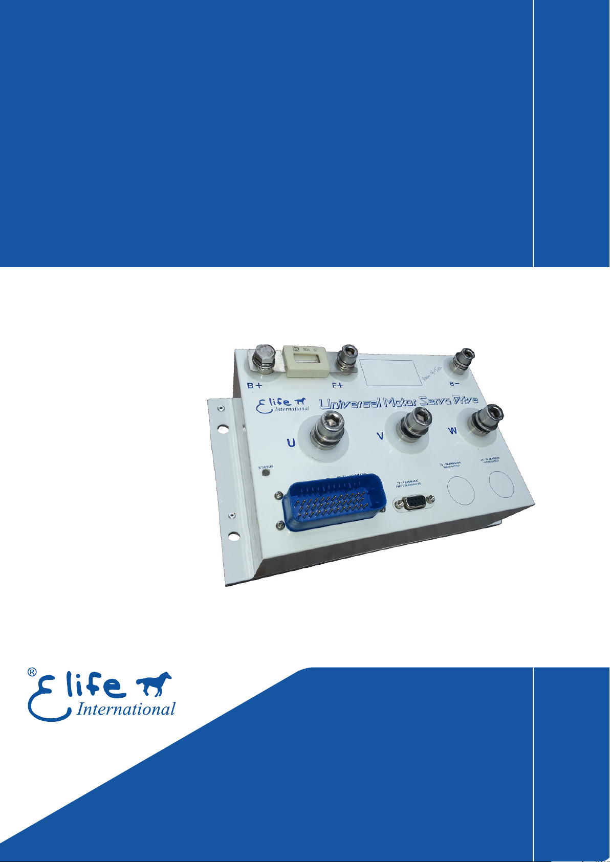
Brushless Edition - Rev. B
UNIDRIVE M Series
Application
Reference Manual
Page 2

Elife International S.r.l.
Via del Giglio, 4 - 57037 Portoferraio - LI
Isola d’Elba - Toscana - Italy
Tel: +39 0565 944121 Fax: +39 0565 945726
email: [email protected]
This manual is copyrighted of Elife International. All rights are reserved. This manual must not be
copied in whole or in part, nor transferred to any other media or language, without express written
permission of Elife International.
Technical Manual Version: 1.0 #Pre2
Page 3

Contents
1 Overview 1
2 Installation and Wiring 7
2.1 Mounting UNIDRIVE on-board . . . . . . . . . . . . . . . . . . . . . 7
2.2 Connections . . . . . . . . . . . . . . . . . . . . . . . . . . . . . . . . 9
2.2.1 High Power Connections . . . . . . . . . . . . . . . . . . . . . 9
2.2.2 Low Power Connections . . . . . . . . . . . . . . . . . . . . . 12
2.3 Standard Wiring Diagrams and Wiring Instructions . . . . . . . . . . 15
2.3.1 Standalone Mode . . . . . . . . . . . . . . . . . . . . . . . . . 15
2.3.2 PLC Mode . . . . . . . . . . . . . . . . . . . . . . . . . . . . . 19
2.3.3 EV Mode . . . . . . . . . . . . . . . . . . . . . . . . . . . . . 23
2.3.4 CAN Network Mode . . . . . . . . . . . . . . . . . . . . . . . 27
2.3.5 RS232 Mode . . . . . . . . . . . . . . . . . . . . . . . . . . . 30
2.4 Feedback Connector . . . . . . . . . . . . . . . . . . . . . . . . . . . 33
2.4.1 Resolver . . . . . . . . . . . . . . . . . . . . . . . . . . . . . . 34
2.4.2 SinCos Encoder . . . . . . . . . . . . . . . . . . . . . . . . . . 35
2.4.3 Hall Sensor . . . . . . . . . . . . . . . . . . . . . . . . . . . . 35
3 Configuration 37
3.1 Software Overview . . . . . . . . . . . . . . . . . . . . . . . . . . . . 37
3.2 Connect UNIDRIVE to your PC . . . . . . . . . . . . . . . . . . . . . . 38
3.3 Import and Export Parameter Values . . . . . . . . . . . . . . . . . . 38
3.4 Change Programmable Parameters . . . . . . . . . . . . . . . . . . . 39
3.4.1 Operating Mode and Controller Parameters . . . . . . . . . . 40
3.4.2 Motor and Acceleration Parameters . . . . . . . . . . . . . . . 42
3.4.3 Throttle Parameters . . . . . . . . . . . . . . . . . . . . . . . 42
3.4.4 CANopen®Parameters . . . . . . . . . . . . . . . . . . . . . . 43
3.4.5 Locked Parameters . . . . . . . . . . . . . . . . . . . . . . . . 44
3.4.6 Advanced Parameters . . . . . . . . . . . . . . . . . . . . . . 47
3.5 Auto-tuning UNIDRIVE Parameters . . . . . . . . . . . . . . . . . . . 50
3.5.1 Gain Parameters for closed-loop Current Control . . . . . . . 50
3.5.2 Offset Resolver/SinCos . . . . . . . . . . . . . . . . . . . . . . 51
3.6 EV Mode . . . . . . . . . . . . . . . . . . . . . . . . . . . . . . . . . . 53
i
Page 4

4 Monitoring UNIDRIVE 57
4.1 LED Diagnostics . . . . . . . . . . . . . . . . . . . . . . . . . . . . . . 57
4.2 Reading Telemetry Data from Telemetry Panel . . . . . . . . . . . . . 57
4.2.1 Alarm Indicators . . . . . . . . . . . . . . . . . . . . . . . . . 60
4.2.2 Reset all Current Alarms . . . . . . . . . . . . . . . . . . . . . 61
4.2.3 Digital I/O and Drive State Indicators . . . . . . . . . . . . . . 62
4.2.4 The Target Velocity/Torque Track Bar . . . . . . . . . . . . . . 63
4.3 Plot and Log Telemetry Data in Real-Time . . . . . . . . . . . . . . . 64
5 Maintenance 67
A Troubleshooting: Alarm Messages 69
B Index of Programmable Parameters 77
List of Tables
1.1 The common features of all models of UNIDRIVE M Series . . . . . . . 3
1.2 An overview of the UNIDRIVE M Series Models . . . . . . . . . . . . . 3
2.1 A summary table of high-power connections, except the M4896-X Type. 10
2.2 Fuse size in accordance with the UNIDRIVE Type. . . . . . . . . . . . . 11
2.3 The pins’ description for the J1 - COMMAND connector. . . . . . . . . . . 12
2.4 UNIDRIVE I/O definitions for Standalone Mode. . . . . . . . . . . . . 16
2.5 UNIDRIVE I/O definitions for PLC Mode . . . . . . . . . . . . . . . . . 19
2.6 CAN bus address selector switch at the node set to 0. . . . . . . . . . . 22
2.7 UNIDRIVE I/O definitions for EV Mode. . . . . . . . . . . . . . . . . . 23
2.8 UNIDRIVE I/O definitions for Can Network Mode . . . . . . . . . . . . 27
2.9 UNIDRIVE I/O definitions for RS232 Mode. . . . . . . . . . . . . . . . 30
2.10
2.11
2.12
Pinout Description of the
connect a Resolver to your UNIDRIVE. . . . . . . . . . . . . . . . . . . 34
Pinout Description of the
connect a SinCos Encoder to your UNIDRIVE. . . . . . . . . . . . . . . 35
Pinout Description of the
connect a Hall Sensor to your UNIDRIVE. . . . . . . . . . . . . . . . . 35
J2 - FEEDBACK
J2 - FEEDBACK
J2 - FEEDBACK
connector (See Figure 2.14) to
connector (See Figure 2.14) to
connector (See Figure 2.14) to
4.1 Description of Digital I/O indicators in Telemetry Panel. . . . . . . . . 62
4.2 Plotting and logging telemetry data with Telemetry Panel. . . . . . . . 65
B.1 Index of UNIDRIVE Programmable Parameters in alphabetical order. . 77
ii
Page 5

Overview
1
UNIDRIVE
low-voltage servomotors, specifically for use in battery powered devices.
The compact form was made possible thanks to the high efficiency of the design,
manufactured with state-of-art electronic components.
UNIDRIVE is highly configurable, a wide range of programmable parameters allow
you to customize your system for your needs.
The main key features include:
•
•
•
•
is the new family of drivers designed to drive the various types of
Designed to drive from 24 V to 96 V Brushless, Brushed and AC ServoMotors.
The different types of feedback are supported:
Encoder, Hall Sensors, Sensorless, Incremental Encoder, Tachometer.
Advanced algorithms for predictive speed and tourque control.
CANopen®communication protocol1: CiA®DS301 and CiA®DSP402 (Interface
Profile Velocity and Interpolated Position Mode and Torque Profile Mode)
Absolute Resolver
, SinCos
•
Electromagnetic Holding Brake Output with DPR System (Dynamic Power
Reduction)
•
Dedicated Safe Torque Off (STO) input
•
Telemetry of the Internal functions
•
Integrated Fuse Holder (only up 80 V)
•
European ConformityC, and designed and tested in accordance with the
emission (EN 61000-6-4) and immunity (EN 61000-6-2) standards. UNIDRIVE
is compliant with EN 60950-1 safety requirements.
1
Elife International is a Member of CiA®- CAN in Automation
EMC
1
Page 6
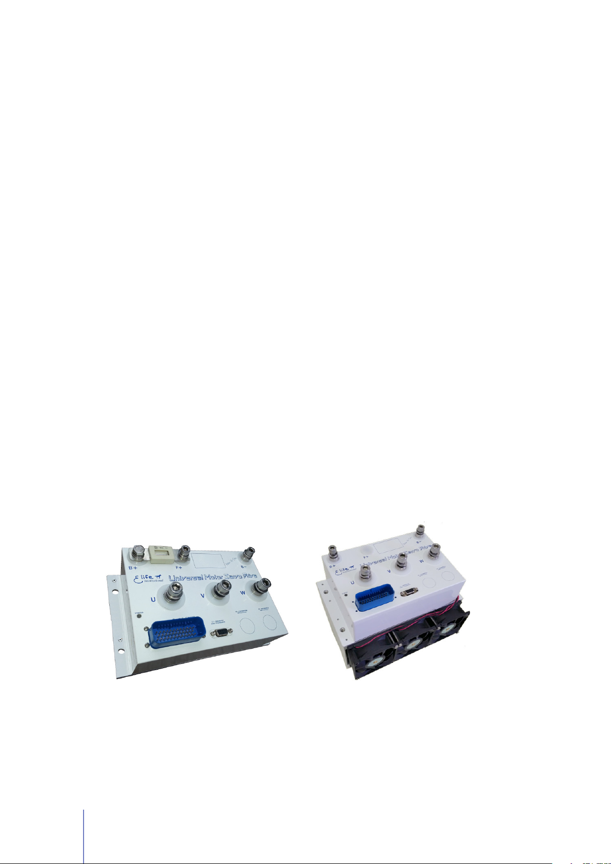
Specification:
Four Quadrant Regenerative Operation
Space Vector Modulation Technology
Sinusoidal and Trapezoidal Commutation Methods
Programmable Gain Setting
Fully Configurable Velocity and Position Limits
PIDF and PID + FF Velocity Loop
On-the-fly Mode and Gain Set Switching
Emergency Deceleration Ramp and Safe Torque Off (STO) Input
Programmable Input/Output:
ë Two High Powered Digital Outputs
ë One 12-bit Analog Output 0÷10 V ê Two 12-bit Analog Inputs 0 ÷ 10 V
ê Eight Digital Inputs Single Ended ë Five Digital Outputs Singled Ended
(a) Electrical Box Version
Size: 250x150x75 mm
(b) Fan Cooler Version
Size: 250x190x150 mm
Figure 1.1: UNIDRIVE series M enables you to drive from 24 V to 96 V Brushless, Brushed
and AC ServoMotors. It’s available in two configurations: (a) Electrical Box with container
and (b) with factory-installed cooling fan.
2 Chapter 1 Overview
Page 7

Table 1.1: The common features of all models of UNIDRIVE M Series
VALUE
PWM Operating Frequency:
Electrical Insulation at Heat Sink:
Digital Input Pin Current:
Digital Input Pin Voltage:
Digital Output Pin Current:
Digital Output Pin Voltage:
Power Output Current:
(for brake and power relay)
Power Output Voltage:
(for brake and power relay)
Analog Input/Output Voltage:
Package Environmental Rating:
Weight:
Dimensions H x W x D:
6103 Hz
500 V (minimum)
1.0 mA @24 V
up to 36 V
up to 250 mA
From 6 to 30 V
up to 2 A
From 6 to 30 V
From 0 to 10 V
IP 66
4.1 Kg (Electrical Box Version)
10.2 Kg (with Fan Cooler)
250x150x57 mm (Electrical Box Version)
250x190x150 mm (with Fan Cooler)
A broad range of models enable us to satisfy every requirements and to suggest
the best solution for your system. An overview of the
UNIDRIVE M
Series Models
is shown in Table 1.2. For other models, have a look at UNIDRIVE S Series and
UNIDRIVE H Series for lower power models or at UNIDRIVE P Series for higher power
models.
Table 1.2: An overview of the UNIDRIVE M Series Models
CO NTINUOU S RMS
NO MINAL VOLTAGE SUPPLY
MA XIMUM
DR IVER
PH ASE CURRE NT *
(Operating Range)
OU TPUT POWER
24 V
M2424-4-X up to 150 Arms
4 KW
(18 Vmin - 32 Vmax )
24 V
M2424-8-X up to 300 Arms
8 KW
(18 Vmin - 32 Vmax )
24 V
M2424-10-X up to 400 Arms
10 KW
(18 Vmin - 32 Vmax )
Continued on next page . . .
3
Page 8

. . . continued from previous page
DR IVER
CO NTINUOU S RMS
PH ASE CURRE NT *
M2436-4-X up to 150 Arms
M2436-8-X up to 300 Arms
M2436-10-X up to 400 Arms
M2436-14-X up to 450 Arms
M2448-4-X up to 150 Arms
M2448-8-X up to 300 Arms
M2448-10-X up to 400 Arms
M2448-16-X up to 450 Arms
NO MINAL VOLTAGE SUPPLY
(Operating Range)
36 V
(18 Vmin - 55 Vmax )
36 V
(18 Vmin - 55 Vmax )
36 V
(18 Vmin - 55 Vmax )
36 V
(18 Vmin - 55 Vmax )
48 V
(18 Vmin - 80 Vmax )
48 V
(18 Vmin - 80 Vmax )
48 V
(18 Vmin - 80 Vmax )
48 V
(18 Vmin - 80 Vmax )
MA XIMUM
OU TPUT POWER
4 KW
8 KW
10 KW
14 KW
4 KW
8 KW
10 KW
16 KW
M4896-8-X up to 150 Arms
M4896-16-X up to 300 Arms
M4896-20-X up to 400 Arms
* The value of the maximum continuous RMS phase current is ensured with an appropriate heat sink
96 V
8 KW
(43 Vmin - 150 Vmax )
96 V
16 KW
(43 Vmin - 150 Vmax )
96 V
20 KW
(43 Vmin - 150 Vmax )
4 Chapter 1 Overview
Page 9
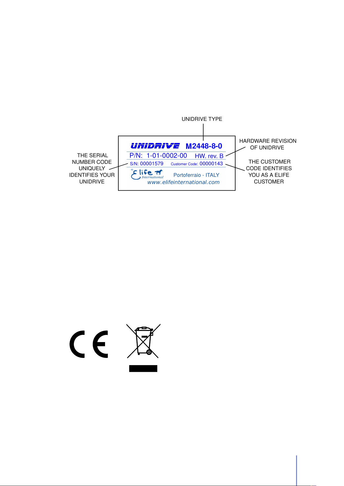
Product Identification Label
2448- -0
S/N: 00001579
Portoferraio - ITALY
www.elifeinternational.com
P/N: 1-01-0002-00
Customer Code: 00000143
HW. rev. B
UNIDRIVE TYPE
HARDWARE REVISION
OF UNIDRIVE
THE CUSTOMER
CODE IDENTIFIES
YOU AS A ELIFE
CUSTOMER
THE SERIAL
NUMBER CODE
UNIQUELY
IDENTIFIES YOUR
UNIDRIVE
M
8
Most of information about your UNIDRIVE - such as serial number, model, customer
information, etc - can be found on a label located on the front of the UNIDRIVE (see
figure below). Some of these information might be requested when you contact the
technical assistance.
Compliance with the EU regulatory requirement for electrical and electronic equipment.
When your UNIDRIVE is no more usable, can’t be treated as generic garbage, but
must be disposed of at a collection point for recycling of electrical and electronic
equipment, in compliance with the
WEEE
regulation (Waste of Electrical and
Electronic Equipment).
5
Page 10

6
Page 11

Installation and Wiring
2.1 Mounting UNIDRIVE on-board
The UNIDRIVE can be mounted in any orientation, but you must choose a location
in order to keep the controller
When you mount the UNIDRIVE on-board you should
dissipation between the UNIDRIVE and the vehicle surface.
UNIDRIVE has a LED light on the front of the device that visually explains what
the driver is doing (see Section 4.1), if you want it to be visible you should take
this into consideration before choosing the location where your UNIDRIVE will be
mounted.
Warning
In order to ensure the proper functioning of the UNIDRIVE you must keep the
controller clean and dry and ensure an effective heat exchange between the
UNIDRIVE and the vehicle surface.
clean
and
dry
, aways from sunlight, water and ice.
2
ensure an effective heat
UNIDRIVE M Series is available in two configuration: in
(Figure 1.1a) or with factory-installed Cooling Fan (Figure 1.1b).
Electrical Box Version
UNIDRIVE with Cooling Fan
If your UNIDRIVE has a factory-installed cooling fan, you just make sure that the
installation location chosen guarantees a sufficient air flow to the cooler.
UNIDRIVE in Electrical Box Version
Otherwise, if you have chosen UNIDRIVE in Electrical Box Version, you must ensure
that the installation on board guaranteeing an adequate heat exchange between the
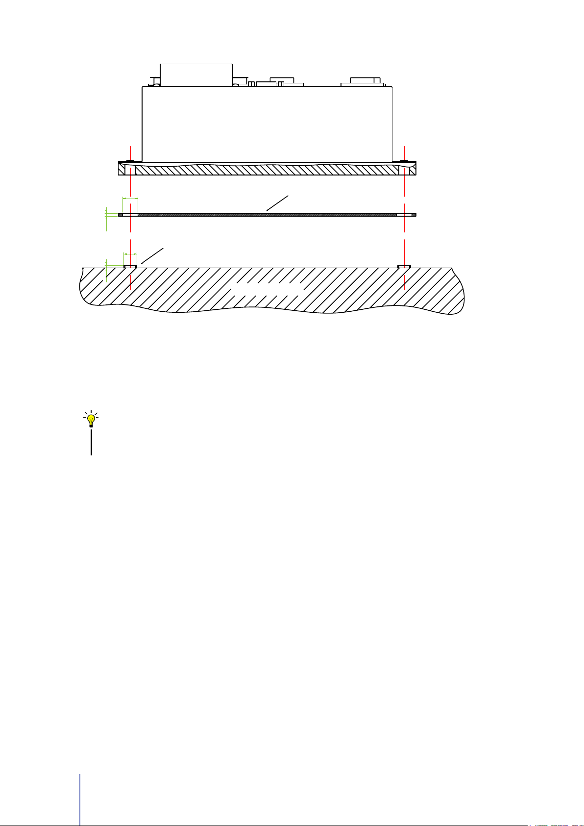
UNIDRIVE and the vehicle surface. In Figure 2.1 is shown a suggested installation
method in order to ensure an effective heat dissipation between the UNIDRIVE and
the vehicle board.
7
Page 12
ALUMINIUM PLATE
THREADED METAL INSERT
D2
H2
D1
H1
VEHICLES BOARD
UNIDRIVE M Series
Figure 2.1:
A recommended installation method in order to ensure an effective heat
dissipation between the UNIDRIVE and the vehicle surface. The D2(H2) size listed in
figure must be greater than D1(H1) size. A thermal grease should be used on both sides of
aluminum plate to improve the heat exchange between UNIDRIVE and the vehicle board.
The additional aluminum plate is not included on UNIDRIVE.
Tips and Advice
A thermal grease should be used on the rear side of the UNIDRIVE heatsink to
improve the heat exchange between UNIDRIVE and the vehicle surface.
If the installation method shown in Figure 2.1 is not sufficient to ensure an effective
heat dissipation from the UNIDRIVE, you should install a Fan Cooler or a Liquid
Cooler on your UNIDRIVE.
8 Chapter 2 Installation and Wiring
Page 13
2.2 Connections
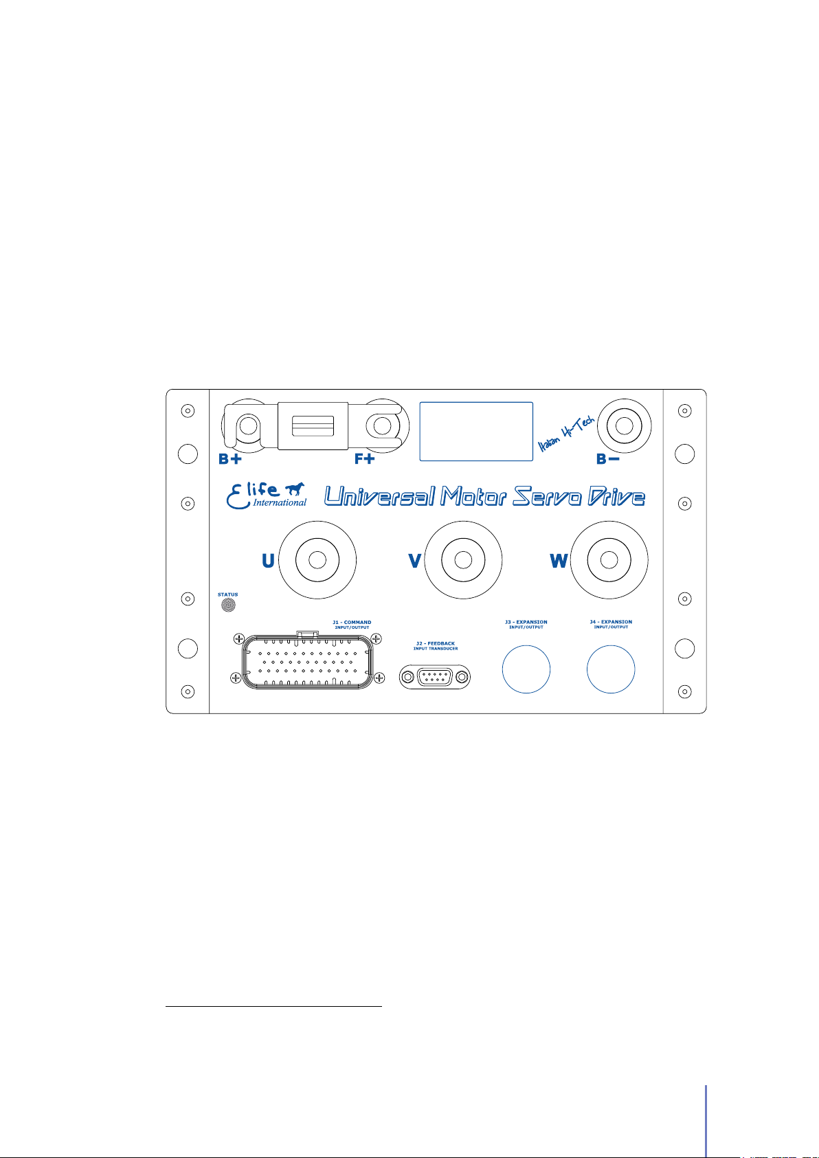
UNIDRIVE on the front, see Figure 2.2, has different types of connectors:
High Power Connections
The three-phase alternating-current generated by UNIDRIVE
is supplied through theU,V,Wterminals. TheF+,B-are the positive1and
negative terminals to connect to your battery.
Low Power Connections
A 35-pin male connector (
J1 - COMMAND
) for low power
logic control.
Feedback Connections
A 9-pin female low power connector (
J2 - FEEDBACK
connect your feedback board.
) to
Figure 2.2:
Power Connections (U,V,W,F+,B-,B+), Low Power Connections (
UNIDRIVE has different types of connectors that can be categorized in: High
Feedback Connector (J2 - FEEDBACK). The fuse isn’t included in M4896-X Type.
2.2.1 High Power Connections
High power connections are provided by: 3-phase supply terminals (U,V,W) and
two terminals for battery connections (F+ or B+,B-).
In order to connect correctly UNIDRIVE, you should use the following instructions:
1.
Except the
Table 2.2) between F+ and B+ terminal to avoid damage to the controller.
1
For M4896-X Type you must connect an external fuse to the B+ terminal, see Section 2.2.1.
M4896-X
Type, you must mount an appropriately sized fuse (See
J1 - COMMAND
2.2 Connections 9
) and
Page 14
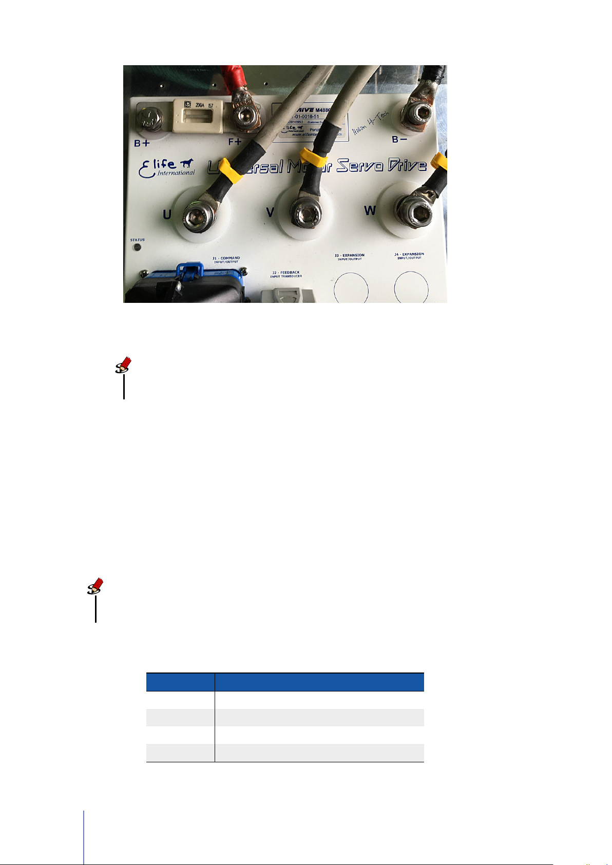
Figure 2.3: UNIDRIVE M Series - High-power connections.
Note
All UNIDRIVE models, except the
installed.
2.
Connect the
cable to the B- terminal.
For
(see Table 2.2 and the Wiring Diagrams).
3.
Connect the U, V, and W motor phases to the 3-phase supply terminals
(U,V,W).
battery positive
M4896-X
Type you must connect an external fuse to the
cable to theF+terminal and the
M4896-X Type
, have a fuse already
battery negative
Note
The
tightening torque
11 N·m for battery connections (F+,B-,B+).
must be
14 N·m
for phase connections (U,V,W) and
B+
terminal
Table 2.1: A summary table of high-power connections, except the M4896-X Type.
TE RMINAL CO NNECT TO
F+ Battery positive terminal to the fuse link
B+ Fuse terminal
B- Battery negative terminal
U,V,W U, V, and W motor phases
10 Chapter 2 Installation and Wiring
Page 15

Warning
Make sure when you connect the high-power cables that the feedback cable
passes as far as possible from the power cables and they are not located close
to each other, in order to avoid electromagnetic interference.
Table 2.2: Fuse size in accordance with the UNIDRIVE Type.
UNIDRIVE TYPE FU SE RATIN G
M2448-4 , M4896-8 * 80 A
M2436-4 100 A
M2424-4 , M2448-8 , M4896-16 * 150 A
M2436-4 , M2448-8 , M4896-20 * 200 A
M2436-10 250 A
M2424-8 , M2448-16 300 A
M2436-14 350 A
M2424-10 400 A
* The models that are written in boldface require an external fuse.
2.2 Connections 11
Page 16
2.2.2 Low Power Connections
1
12
13 23
35
24
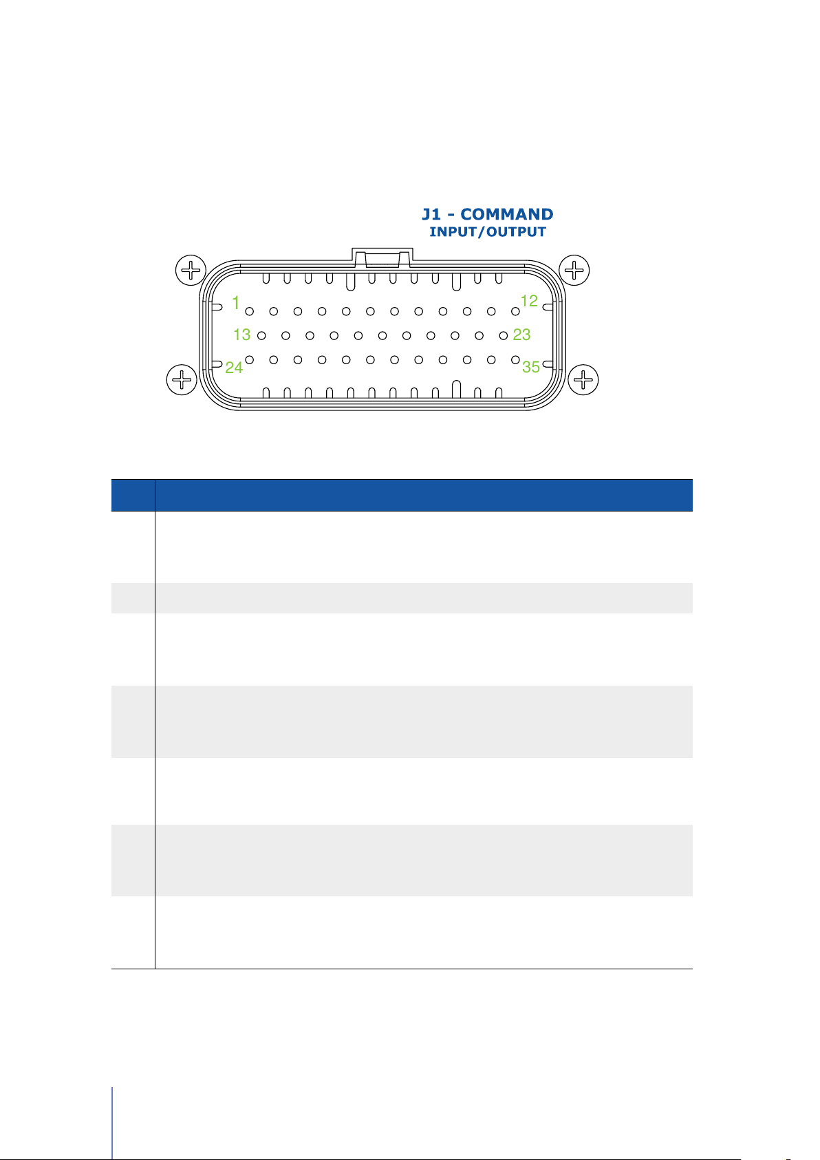
The low power logic control connections are provided by a 35-pin male connector
(J1 - COMMAND). The pins’ description is given in Table 2.3.
Table 2.3: The pins’ description for the J1 - COMMAND connector.
PI N I/O TYPE DE SCRIPTIO N OP ERATI NG RANGE
From 18 to 80 V
(Only for M4896-X Type:
From 43 to 160 V)
1 KEY (+BATT)
Internal logic circuits power
supply, it should be protected
with 2A delayed fuse, type T
2 OUTPUT GND Digital output common /
Output Voltage in according
to the Input voltage on PIN 5
I
MAX
Output Voltage in according
to the Input voltage on PIN 5
I
MAX
From 6 to 30 V
3 BRAKE
LINE
4
CONTACTOR
OUT
5 +24V INPUT
Brake supply with
programmable dynamic power
reduction
Driver main contactor output
Power supply for output pins, it
should be protected with 4A
delayed fuse, type T
Output Voltage in according
6 OUT1
7 OUT2
Encoder A emulator, single
phase
Encoder B emulator, single
phase
to the Input voltage on PIN 5
I
=250 mA
MAX
Output Voltage in according
to the Input voltage on PIN 5
I
=250 mA
MAX
Continued on next page . . .
=2 A
=2 A
12 Chapter 2 Installation and Wiring
Page 17
. . . continued from previous page
PI N I/O TYPE DE SCRIPTIO N OP ERATI NG RANGE
Speed potentiometer supply
output. The value of output
8 PWR POT
voltage can be selected in
Potentiometer Supply option
(See Section 3.4.6, Pag. 49)
9 ANALOG OUT Analog output From 0 to +10 V
V
= 5 or 10 V
OUT
I
MAX
=250 mA
10 TX1 RS232
11 RX1 RS232
12 SAFETY Safety Input V
TX output – module 1, it is used
to download firmware update
RX output – module 1, it is used
to download firmware update
Standard RS232
Standard RS232
= 36 V, High > 11 V
MAX
13 GND INPUT Digital inputs common /
14 IN1 Digital input 1 V
15 IN2 Digital input 2 V
16 IN3 Digital input 3 V
17 IN4 Digital input 4 V
= 36 V, High > 11 V
MAX
= 36 V, High > 11 V
MAX
= 36 V, High > 6 V
MAX
= 36 V, High > 11 V
MAX
Output Voltage in according
18 OUT3 Digital Output 3
19
AIN /
WIPER POT 1
AIN /
20
WIPER POT 2
Single ended analog input 1 /
Wiper input for speed throttle
Single ended analog input 2 /
Wiper input for aux throttle
to the Input voltage on PIN 5
I
=250 mA
MAX
From 0 to +10 V
From 0 to +5 V
From 0 to +10 V
TX output – module 2, it is used
21 TX2 RS232
22 RX2 RS232
23 SERIAL GND
24 -BATT
to communicate with RS232 in
order to realize Telemetry panel
RX Input – module 2, it is used
to communicate with RS232 in
order to realize Telemetry panel
RS232 Common for modules 1
and 2
Common ground, it should be
connected to the negative
terminal of battery
25 IN5 Digital input 5 V
Continued on next page . . .
Standard RS232
Standard RS232
/
/
= 36 V, High > 11 V
MAX
2.2 Connections 13
Page 18

. . . continued from previous page
PI N I/O TYPE DE SCRIPTIO N OP ERATI NG RANGE
26 IN6 Digital input 6 V
27 IN7 Digital input 7 V
28 IN8 Digital input 8 V
29 OUT4
Drive fault alarm output, it
changes its current state
whenever an alarm is present.
See Section 3.4.1, Pag. 41
Output Voltage in according
to the Input voltage on PIN 5
= 36 V, High > 11 V
MAX
= 36 V, High > 11 V
MAX
= 36 V, High > 11 V
MAX
I
=250 mA
MAX
Output Voltage in according
30 OUT5 Digital Output 5
31 ANALOG GND
Analog Common /
Potentiometer Low Input
to the Input voltage on PIN 5
I
=250 mA
MAX
32 SERVICE Do not use /
33 CAN-
34 CAN+
CAN_L bus line (dominant low)
CAN_H bus line (dominant
high)
Standard CAN
Standard CAN
/
35 GND CAN CAN bus common /
Note
The digital inputs have over-voltage protection up to battery voltage.
Concluded
14 Chapter 2 Installation and Wiring
Page 19
2.3 Standard Wiring Diagrams and Wiring Instructions
This section contains standard wiring diagrams to be used to connect your
M Series
operating mode in which the UNIDRIVE works to drive a Brushless Servomotor.
It’s also possible to connect two or more UNIDRIVE together for specific application
(e.g: steering wheel control) and drive different types of servomotor. These advanced
installations will not be dealt with in the present manual.
on your system. The following wiring diagrams cover only the standard
UNIDRIVE
Warning
The following wiring diagrams and operating instructions should be read
carefully and completed before wiring your UNIDRIVE up on your system.
The wiring diagram must be chosen in according to the operating mode
(PLC, Standalone, EV , CAN, RS323) that suits your needs.
Note
For M4896-X Type you should mount an external fuse, see Section 2.2.1.
2.3.1 Standalone Mode
The Standalone mode is designed to drive your motor with only two inputs: a throttle
and a emergency input.
Other optional inputs can be used to extend the functionality of this operating mode
(See Table 2.4).
For the correct functioning of this operating mode, special attention must be paid
to choose the correct value of Analog Input (See Section 3.4.4) in according to the
throttle characteristics.
Note
If you’ve installed a 0-10V or 0-5V throttle the rotation direction of the motor
should be given through the FORWARD and the BACKWARD input.
When
(FAST/SLOW input).
throttle is put to neutral position
if the brake should be locked or unlocked (HANDBRAKE input) and the speed mode
- before bridge activation - you can indicate
2.3 Standard Wiring Diagrams and Wiring Instructions 15
Page 20
Table 2.4: UNIDRIVE I/O definitions for Standalone Mode.
PI N
I/O
TY PE
NA ME DESCR IPT ION
14 IN1 BACKWARD
15 IN2 FORWARD
16 IN3
17 IN4
26 IN6
28 IN8
FAST/SLOW
HANDBRAKE
EMERGENCY
ALARM
RESET
18 OUT3 STATUS
High = Backward, Low = Stop.
This input is only processed if FORWARD
input is low.
High = Forward, Low = Stop
(only if BACKWARD is low)
High = Slow mode, Low = Fast mode.
This input is processed only before bridge
activation
High = Unlocked, Low = Locked.
This input is processed only before bridge
activation
Emergency input should always be
supplied, otherwise UNIDRIVE stops
motor rotation and unlocks motor brake.
It’s possible to reset all running alarms
with a rising edge signal (transition from
low to high)
It gets steady high when motor is
running and blinking when motor is
stopped. It’s low when there is an alarm.
Optional
Optional
Optional
Optional
Mandatory
Optional
a
a
b
Alarm output, it changes its current state
29 OUT4 ALARM
30 OUT5 REVERSE
a
Mandatory only for 0–10V or 0-5V throttle.
b
Mandatory if you want to switch between Fast and Slow mode, see Section 3.4.2.
whenever an alarm is present. See
Section 3.4.1, Pag. 41
It is the output to connect to buzzer, it
gets high when the rotation direction is
backward.
The Fast and Slow modes are designed to meet two different purposes:
Slow mode
It’s programmable so that the vehicle indoor moves slowly with accurate
operation.
Fast mode It allows a faster velocity for outdoor long distance path.
It’s scheduled both the configuration of the maximum motor velocity and the
maximum velocity at Slow mode (See Section 3.4.2).
The
wiring diagram
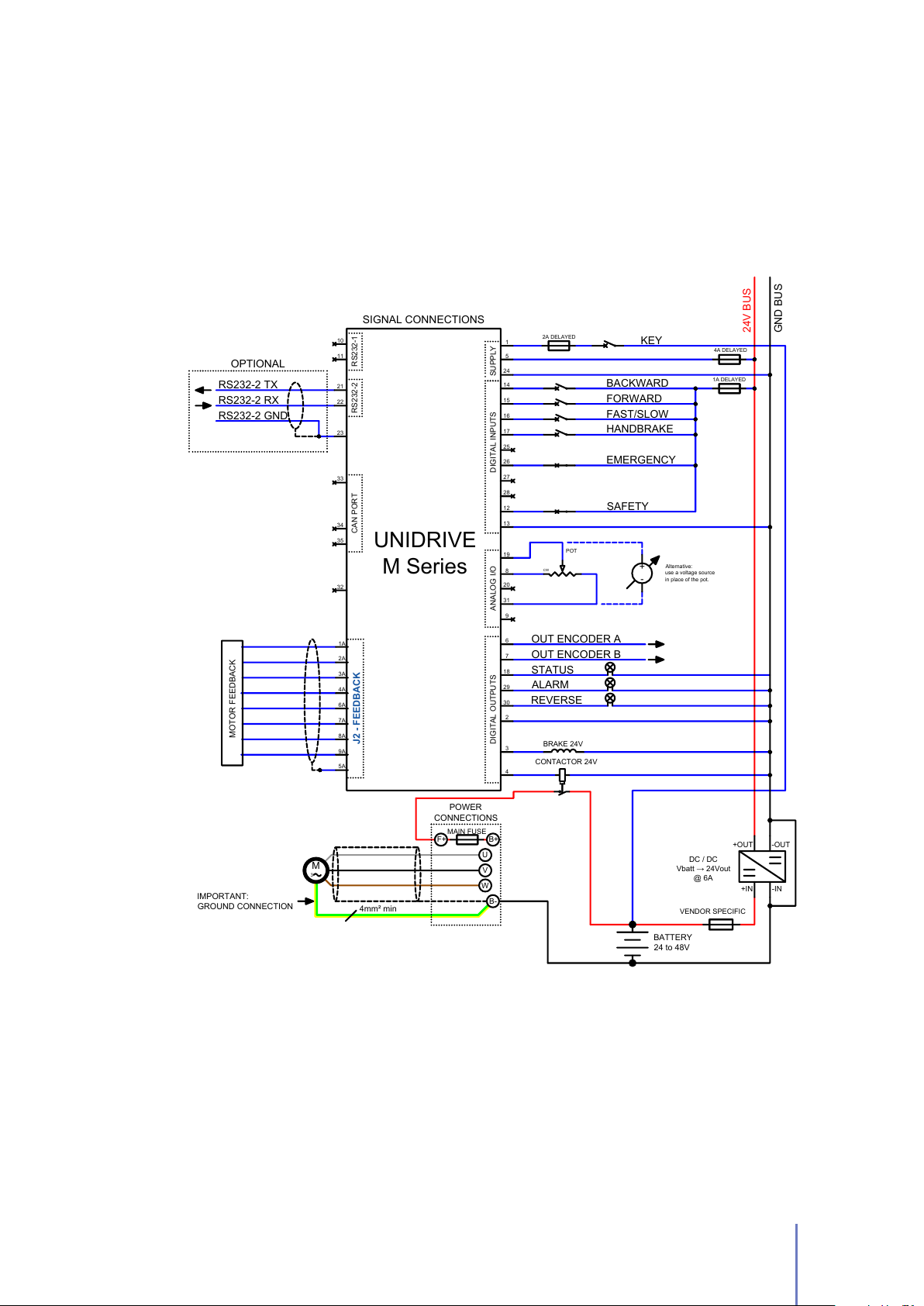
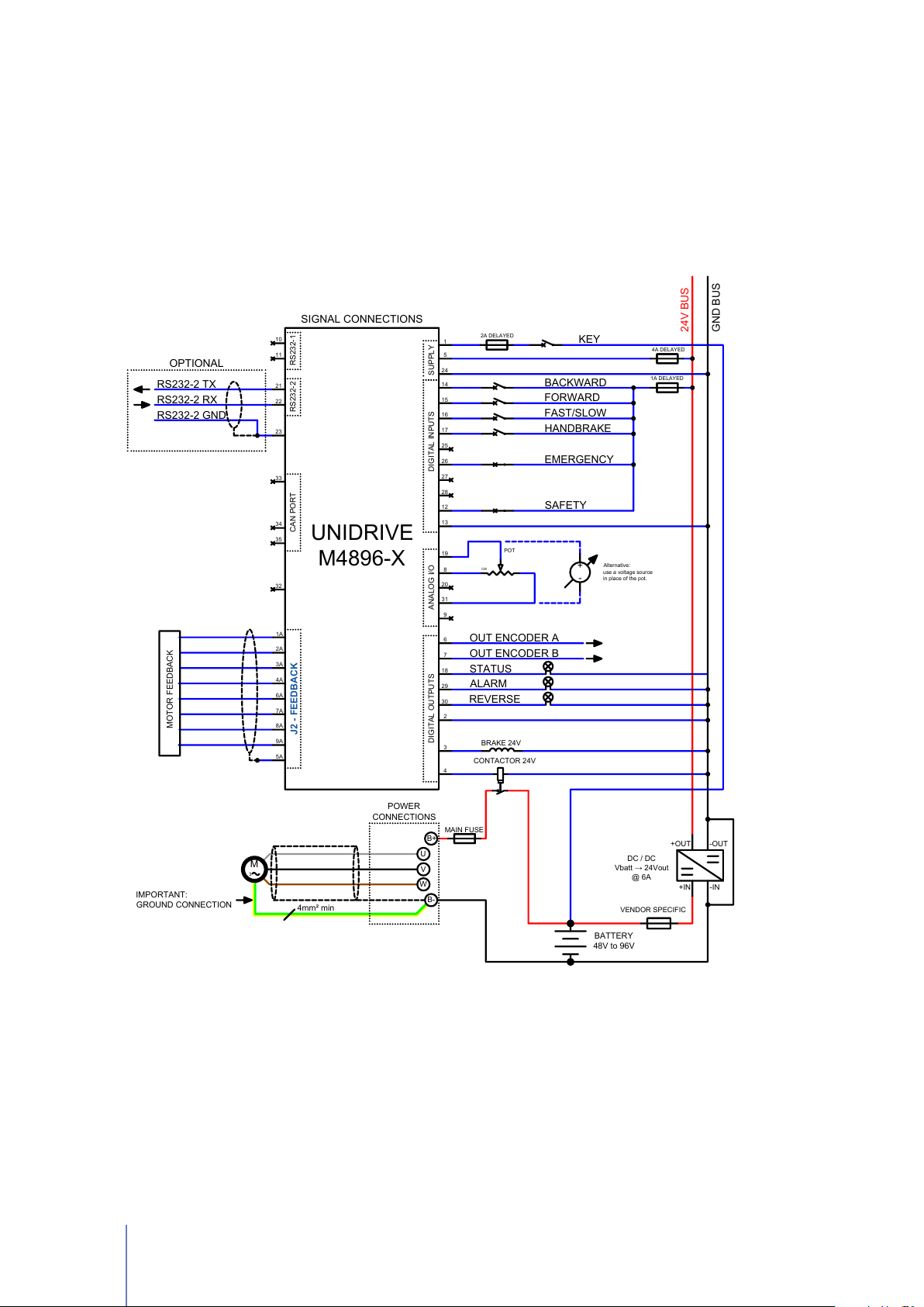
for standalone mode is shown in Figure 2.4 for any UNIDRIVE
M Series Type, except the M4896-x Type (Figure 2.5).
16 Chapter 2 Installation and Wiring
Page 21
Standalone Mode - Wiring Diagram
BRAKE 24V
32
33
34
35
1
14
15
16
17
28
25
26
27
8
20
3
7
6
29
30
18
4
9
31
2
5
24
24V BUS
GND BUS
SIGNAL CONNECTIONS
BACKWARD
KEY
EMERGENCY
2A DELAYED
ALARM
OUT ENCODER A
4A DELAYED
+IN
-IN
+OUT
-OUT
CAN PORT
DIGITAL OUTPUTS
1A DELAYED
SUPPLY
POWER
CONNECTIONS
U
V
W
MAIN FUSE
F+ B+
OUT ENCODER B
FORWARD
FAST/SLOW
CW
POT
REVERSE
STATUS
HANDBRAKE
+
-
Alternative:
use a voltage source
in place of the pot.
RS232-2 TX
RS232-2 RX
RS232-2 GND
OPTIONAL
11
10
21
22
23
RS232-2 RS232-1
19
12
DIGITAL INPUTSANALOG I/O
13
SAFETY
M
3
B-
UNIDRIVE
M Series
1A
2A
3A
4A
6A
7A
8A
9A
5A
J2 - FEEDBACK
MOTOR FEEDBACK
CONTACTOR 24V
BATTERY
24 to 48V
VENDOR SPECIFIC
DC / DC
Vbatt → 24Vout
@ 6A
IMPORTANT:
GROUND CONNECTION
4mm² min
Figure 2.4:
Type - to your system in Standalone Mode.
The wiring diagram to connect your
UNIDRIVE M Series
- except the M4896-X
2.3 Standard Wiring Diagrams and Wiring Instructions 17
Page 22
Standalone Mode - Wiring Diagram [M4896-X Type]
BRAKE 24V
32
33
34
35
1
14
15
16
17
28
25
26
27
8
20
3
7
6
29
30
18
4
9
31
2
5
24
24V BUS
GND BUS
SIGNAL CONNECTIONS
BACKWARD
KEY
EMERGENCY
2A DELAYED
ALARM
OUT ENCODER A
4A DELAYED
+IN
-IN
+OUT
-OUT
CAN PORT
DIGITAL OUTPUTS
1A DELAYED
SUPPLY
POWER
CONNECTIONS
U
V
W
B+
OUT ENCODER B
FORWARD
FAST/SLOW
CW
POT
REVERSE
STATUS
HANDBRAKE
MAIN FUSE
+
-
Alternative:
use a voltage source
in place of the pot.
RS232-2 TX
RS232-2 RX
RS232-2 GND
OPTIONAL
11
10
21
22
23
RS232-2 RS232-1
19
12
DIGITAL INPUTSANALOG I/O
13
SAFETY
M
3
B-
1A
2A
3A
4A
6A
7A
8A
9A
5A
J2 - FEEDBACK
MOTOR FEEDBACK
UNIDRIVE
M4896-X
CONTACTOR 24V
VENDOR SPECIFIC
DC / DC
Vbatt → 24Vout
@ 6A
BATTERY
48V to 96V
IMPORTANT:
GROUND CONNECTION
4mm² min
Figure 2.5:
in Standalone Mode
The wiring diagram to connect your UNIDRIVE
M4896-X
Type to your system
18 Chapter 2 Installation and Wiring
Page 23
2.3.2 PLC Mode
The PLC mode is a flexible, self-contained operating mode for automatic vehicles
(AGV).
The details of inputs and output of this operating mode are shown in Table 2.5.
Table 2.5: UNIDRIVE I/O definitions for PLC Mode
PI N
NA ME DESCR IPT ION
TY PE
I/O
14 IN1
15 IN2 DIR
16 IN3
17 IN4
26 IN6
27 IN7
28 IN8
RUN / STOP
FAST/SLOW
CCW
OVERTRAVEL
EMERGENCY
CW
OVERTRAVEL
ALARM
RESET
High = Run, Low = Stop Mandatory
High = Clockwise,
Low = Counterclockwise
High = Slow mode, Low = Fast mode.
This input is processed only before bridge
activation
High = Active Overtravel for CCW
rotation, Low = Inactive Overtravel
Emergency input should always be
supplied, otherwise UNIDRIVE stops
motor rotation and unlocks motor brake.
High = Active Overtravel for CW
rotation, Low = Inactive Overtravel
It’s possible to reset all running alarms
with a rising edge signal (transition from
low to high)
Optional
Optional
Optional
Mandatory
Optional
Optional
a
b
c
c
Alarm output, it changes its current state
29 OUT4 ALARM
a
Mandatory only for 0–10V or 0-5V throttle.
b
Mandatory if you want to switch between Fast and Slow mode, see Section 3.4.2.
c
It is processed only if overtravels are enabled by Telemetry panel, see Section 3.4.6.
whenever an alarm is present. See
Section 3.4.1, Pag. 41
For the correct functioning of this operating mode, special attention must be paid
to choose the correct value of Analog Input (See Section 3.4.4) in according to the
throttle characteristics.
Note
If you’ve installed a 0-10V or 0-5V throttle the rotation direction of the motor
should be given through DIR input.
2.3 Standard Wiring Diagrams and Wiring Instructions 19
Page 24
PLC Mode - Wiring Diagram
BRAKE 24V
32
33
34
35
1
14
15
16
17
28
25
26
27
8
20
19
3
7
6
29
30
18
4
9
31
12
2
5
24
24V BUS
GND BUS
SIGNAL CONNECTIONS
RUN / STOP
KEY
EMERGENCY
2A DELAYED
ALARM
OUT ENCODER A
RS232-2 TX
RS232-2 RX
RS232-2 GND
4A DELAYED
ANALOG INPUT
ANALOG GND
+IN
-IN
+OUT
-OUT
CAN PORT
DIGITAL INPUTSDIGITAL OUTPUTS ANALOG I/O
OPTIONAL
1A DELAYED
SUPPLY
POWER
CONNECTIONS
U
V
W
F+ B+
OUT ENCODER B
DIR
FAST/SLOW
MAIN FUSE
CAN-
CAN+
See manual for details
11
10
21
22
23
RS232-2 RS232-1
13
SAFETY
M
3
B-
UNIDRIVE
M Series
1A
2A
3A
4A
6A
7A
8A
9A
5A
J2 - FEEDBACK
MOTOR FEEDBACK
CONTACTOR 24V
BATTERY
24 to 48V
DC / DC
Vbatt → 24Vout
@ 6A
VENDOR SPECIFIC
4mm² min
IMPORTANT:
GROUND CONNECTION
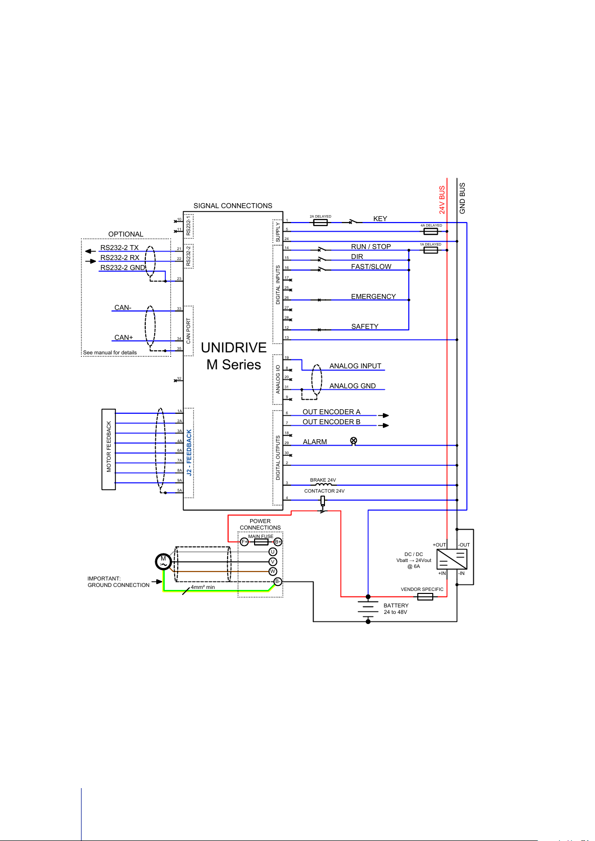
Figure 2.6:
Type - to your system in PLC Mode.
The wiring diagram to connect your
UNIDRIVE M Series
- except the M4896-X
20 Chapter 2 Installation and Wiring
Page 25
PLC Mode - Wiring Diagram [M4896-X Type]
BRAKE 24V
32
1
14
15
16
17
28
25
26
27
8
20
3
7
6
29
30
18
4
9
31
2
5
24
24V BUS
GND BUS
SIGNAL CONNECTIONS
RUN / STOP
KEY
EMERGENCY
2A DELAYED
ALARM
OUT ENCODER A
4A DELAYED
ANALOG INPUT
ANALOG GND
+IN
-IN
+OUT
-OUT
DIGITAL OUTPUTS
1A DELAYED
SUPPLY
POWER
CONNECTIONS
U
V
W
B+
OUT ENCODER B
DIR
FAST/SLOW
MAIN FUSE
19
12
DIGITAL INPUTSANALOG I/O
13
SAFETY
33
34
35
RS232-2 TX
RS232-2 RX
RS232-2 GND
CAN PORT
OPTIONAL
CAN-
CAN+
See manual for details
11
10
21
22
23
RS232-2 RS232-1
M
3
B-
UNIDRIVE
M4896-X
1A
2A
3A
4A
6A
7A
8A
9A
5A
J2 - FEEDBACK
MOTOR FEEDBACK
CONTACTOR 24V
VENDOR SPECIFIC
DC / DC
Vbatt → 24Vout
@ 6A
IMPORTANT:
GROUND CONNECTION
4mm² min
BATTERY
48V to 96V
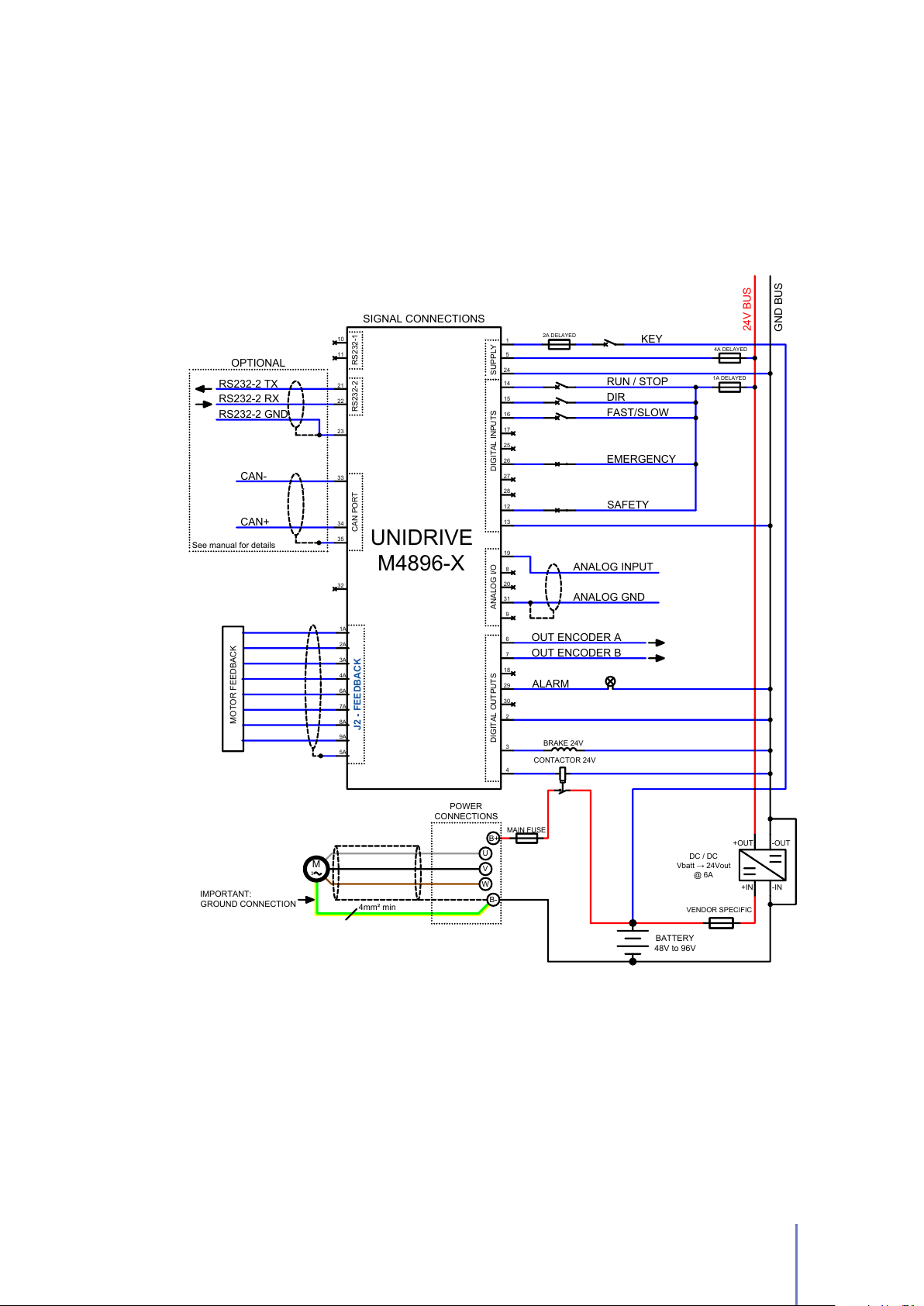
Figure 2.7:
in PLC Mode.
The wiring diagram to connect your UNIDRIVE
M4896-X
Type to your system
2.3 Standard Wiring Diagrams and Wiring Instructions 21
Page 26
When the RUN / STOP input gets high the brake is unlocked and the motor starts to
spin-up. If overtravels are enabled by Telemetry panel (see Section 3.4.6) UNIDRIVE
will stop the motor when one of two over-travel inputs (CCW OVERTRAVEL and CW
OVERTRAVEL) will get high.
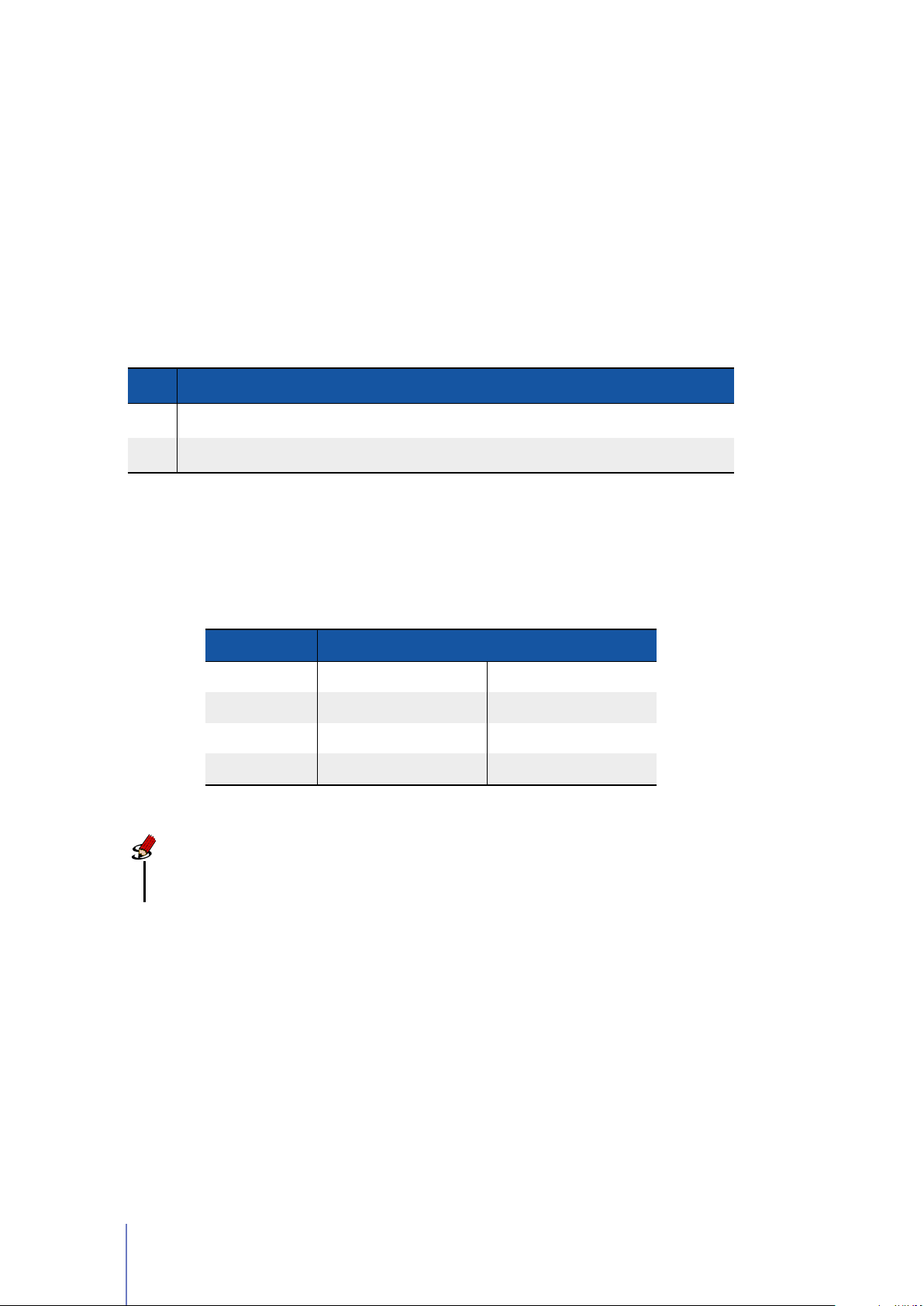
In this configuration it is also possible to read the most important information
through
Table 2.6.
Table 2.6: CAN bus address selector switch at the node set to 0.
CAN
bus. In this case the
IN7
and
IN8
input could be used as shown in
PI N I/O TYPE NAME DE SCRIPTIO N
27 IN7 CAN ADR0
28 IN8 CAN ADR1
In case that the CAN address is set to0through Telemetry panel, after switch-on it
is possible to appoint the node-ID depending on two digital inputs: CAN ADR0 and
CAN ADR1, in the following way:
It could be used as CAN address selector 0
It could be used as CAN address selector 1
CAN NODE INPUT CONFIGURATION
1 CAN ADR1 * GND CAN ADR0 * GND
2 CAN ADR1 * GND CAN ADR0 * +24V
3 CAN ADR1 * +24V CAN ADR0 * GND
4 CAN ADR1 * +24V CAN ADR0 * +24V
Note
Please note that if CAN address is set to 0, PI N 28 won’t be a ALARM RESET
input.
22 Chapter 2 Installation and Wiring
Page 27
2.3.3 EV Mode
The EV mode is specially designed to control motors mounted in Electric Vehicles
(EV). This operating mode employs sophisticated proprietary algorithms to offer
you a driving experience as much as possible similar to traditional gasoline engine
vehicles. A detailed explanation of this operating mode is given in Section 3.6.
For the correct functioning of this operating mode, you must install only 0–10V or
0-5V throttle and choose the correct value of Analog Input (See Section 3.4.4) in
according to the throttle characteristics.
Note
In this operating mode the rotation direction of the motor should be given
through the FORWARD and the BACKWARD input.
Table 2.7: UNIDRIVE I/O definitions for EV Mode.
PI N
I/O
TY PE
NA ME DESCR IPT ION
14 IN1 BACKWARD
15 IN2 FORWARD
16 IN3
17 IN4
26 IN6
28 IN8
SPORT /
ECONOMY
HANDBRAKE
EMERGENCY
ALARM
RESET
18 OUT3 STATUS
High = Backward, Low = Stop.
This input is only processed if FORWARD
input is low.
High = Forward, Low = Stop
(only if BACKWARD is low)
High = Sport mode, Low = Economy
mode.
This input is processed only before bridge
activation
High = Unlocked, Low = Locked.
This input is processed only before bridge
activation
Emergency input should always be
supplied, otherwise UNIDRIVE stops
motor rotation and unlocks motor brake.
It’s possible to reset all running alarms
with a rising edge signal (transition from
low to high)
It gets steady high when motor is
running and blinking when motor is
stopped. It’s low when there is an alarm.
Mandatory
Mandatory
Optional
Optional
Mandatory
Optional
a
Alarm output, it changes its current state
29 OUT4 ALARM
30 OUT5
a
Mandatory if you want to switch between SPORT and ECONOMY mode, see Section 3.4.2.
BRAKE
LIGHT
whenever an alarm is present. See
Section 3.4.1, Pag. 41
It is the output to connect to brake light,
it gets high when velocity decreases of at
least set value.
2.3 Standard Wiring Diagrams and Wiring Instructions 23
Page 28
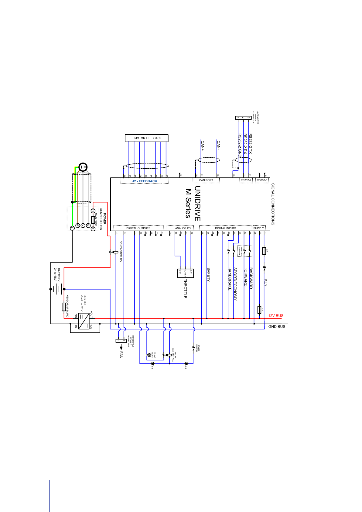
EV Mode - Wiring Diagram
HANDBRAKE
11
10
32
33
34
35
21
22
23
1
14
15
16
172825
26
27
8
20
19
3
7
6
293018
4
9
31
13
2
5
24
12V BUS
GND BUS
SIGNAL CONNECTIONS
BACKWARD
KEY
2A
RS232-2 TX
RS232-2 RX
RS232-2 GND
4A
CAN PORT RS232-2 RS232-1
DIGITAL INPUTSDIGITAL OUTPUTS ANALOG I/O SUPPLY
POWER
CONNECTIONS
U
V
W
M
3
B-
FORWARD
2
FAN
AUTOMOTIVE
FEMALE
CONNECTOR
OUT
SUPPLY
GND
THROTTLE
DIRECTION
SWITCH
RELAY
(Coil 12V 1Wmax)
BRAKE
SWITCH
BRAKE
LIGHT
tbd
tbd
CAN-
CAN+
AUTOMOTIVE
FEMALE
CONNECTOR
1
+
-
1
2
3
SPORT/ECONOMY
12
SAFETY
BATTERY
24 to 48V
DC / DC
Vbatt → 12 V
+IN
-IN
+OUT
-OUT
1A
2A
3A
4A
6A
7A
8A
9A
5A
J2 - FEEDBACK
MOTOR FEEDBACK
UNIDRIVE
M Series
MAIN FUSE
F+ B+
CONTACTOR 12V
VENDOR SPECIFIC
Figure 2.8:
An example of wiring diagram to connect your
the M4896-X Type - to your system in
of the possible ways to wire your system in EV Mode.
24 Chapter 2 Installation and Wiring
EV Mode
. This suggested wiring diagram is just one
UNIDRIVE M Series
- except
Page 29
EV Mode - Wiring Diagram [M4896-X Type]
HANDBRAKE
11
10
32
33
34
35
21
22
23
1
141516
1728252627
8
20
19
3
7
6
293018
4
9
31
13
2
5
24
12V BUS
GND BUS
SIGNAL CONNECTIONS
BACKWARD
KEY
2A
RS232-2 TX
RS232-2 RX
RS232-2 GND
4A
CAN PORT RS232-2 RS232-1
DIGITAL INPUTSDIGITAL OUTPUTS ANALOG I/O SUPPLY
POWER
CONNECTIONS
U
V
W
F+ B+
M
3
B-
FORWARD
MAIN FUSE
2
FAN
AUTOMOTIVE
FEMALE
CONNECTOR
OUT
SUPPLY
GND
THROTTLE
DIRECTION
SWITCH
RELAY
(Coil 12V 1Wmax)
BRAKE
SWITCH
BRAKE
LIGHT
tbd
tbd
CAN-
CAN+
AUTOMOTIVE
FEMALE
CONNECTOR
1
+
-
1
2
3
SPORT/ECONOMY12SAFETY
DC / DC
Vbatt → 12 V
+IN
-IN
+OUT
-OUT
1A2A3A4A6A7A8A9A5A
J2 - FEEDBACK
MOTOR FEEDBACK
UNIDRIVE
M4896-X
CONTACTOR 12V
VENDOR SPECIFIC
BATTERY
48V to 96V
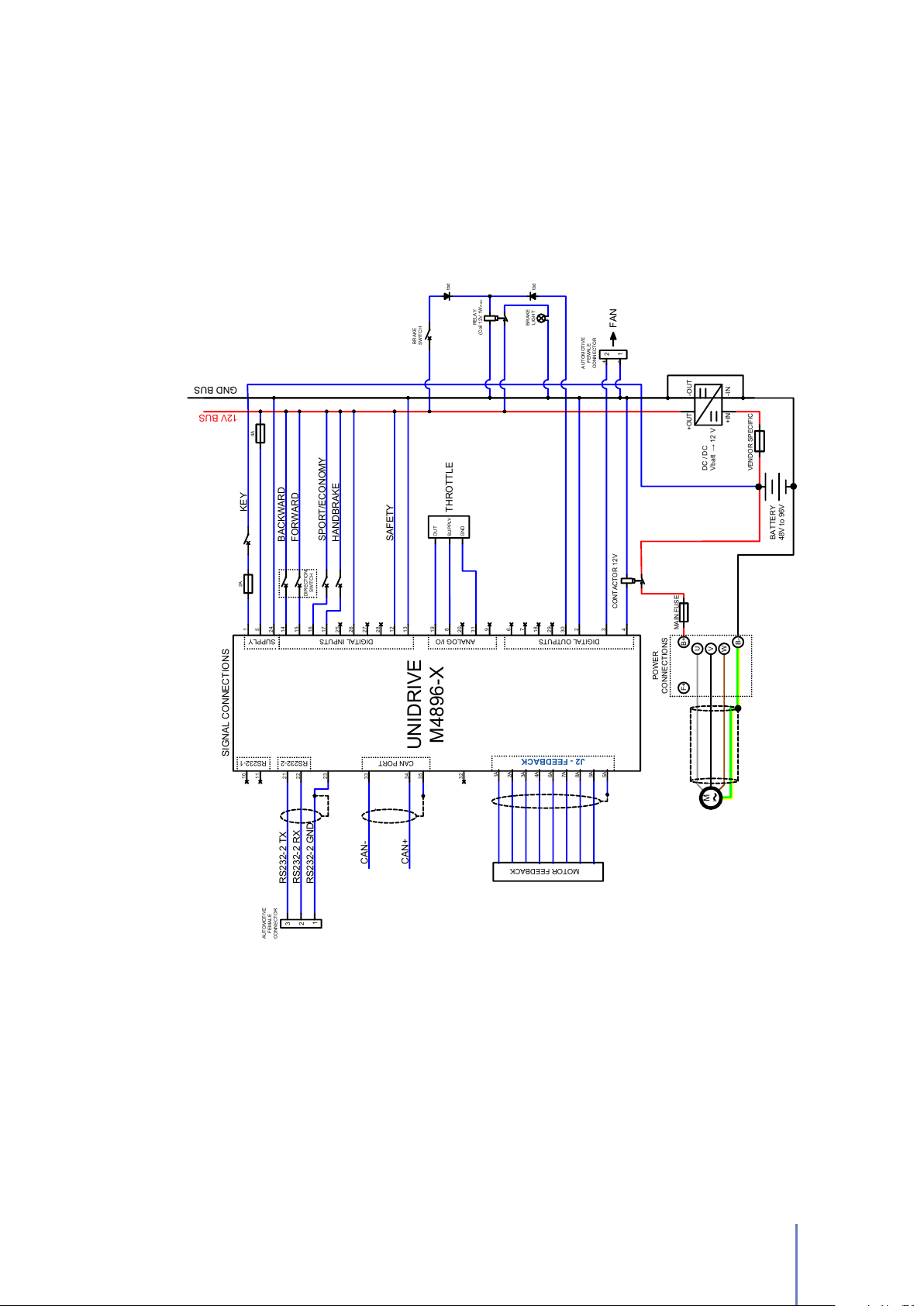
Figure 2.9:
your system in
wire your system in EV Mode.
An example of wiring diagram to connect your UNIDRIVE
EV Mode
. This suggested wiring diagram is just one of the possible ways to
M4896-X
Type to
2.3 Standard Wiring Diagrams and Wiring Instructions 25
Page 30

When
indicate if the brake should be locked or unlocked (HANDBRAKE input), the rotation
direction (BACKWARD or FORWARD) and the speed mode (SPORT/ECONOMY
input).
The SPORT and ECONOMY modes are designed to meet two different purposes:
throttle is put to neutral position
- before bridge activation - you can
ECONOMY mode
battery life. The acceleration ramp is smoother than Sport Mode and the max
power available is limited.
SPORT mode
possible.
It’s scheduled both the configuration of the maximum motor velocity and the
maximum velocity at ECONOMY mode (See Section 3.4.2).
This operating mode is specially designed in order to extend the
The SPORT mode is designed to get the maximum performance as
Note
In this operating mode one of the two power outputs (BRAKE, PIN 3) is used
to power the UNIDRIVE’s fan.
26 Chapter 2 Installation and Wiring
Page 31

2.3.4 CAN Network Mode
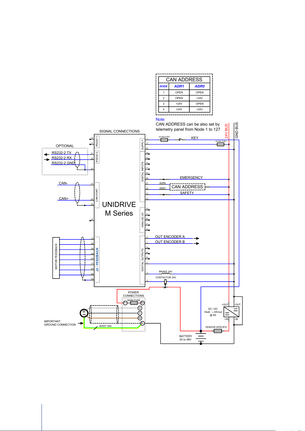
In
CAN Network
For further information about CANopen®protocol, please refer to CiA®DSP402
protocol (version 3.0.1.15) and UNDRIVE CANopen®Manual.
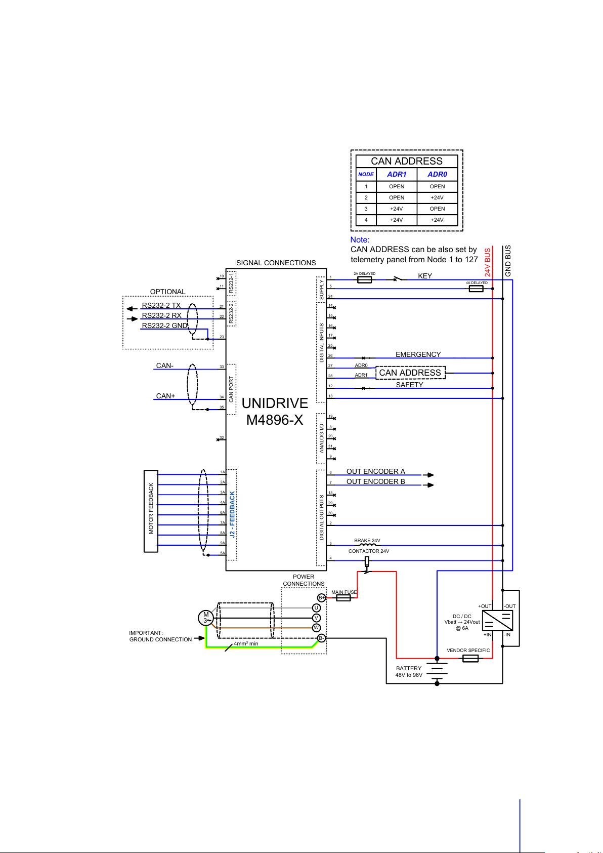
A description of the inputs and outputs connections for this operating mode is shown
in Table 2.8
Table 2.8: UNIDRIVE I/O definitions for Can Network Mode
mode you can control your motor through CANopen®bus protocol.
PI N
NA ME DE SCRIPTIO N
TY PE
16 IN3 BWD It could be used as negative limit switch Optional
17 IN4 FWD It could be used as positive limit switch Optional
I/O
25 IN5
26 IN6
27 IN7 CAN ADR0 It can be used as CAN address selector 0 Optional
28 IN8 CAN ADR1
29 OUT4 ALARM
In this operating mode is needed to set the correct CANopen®parameters via
Telemetry Panel (See Section 3.4.4).
In case that the CAN address is set to0through Telemetry panel, after switch-on it
is possible to appoint the node-ID depending on two digital inputs: CAN ADR0 and
CAN ADR1, in the following way:
HOME
SENSOR
EMERGENCY
It could be used as home switch Optional
Emergency input should always be
supplied, otherwise UNIDRIVE stops
motor rotation and unlocks motor brake.
It could be used as CAN address selector 1
Alarm output, it changes its current state
whenever an alarm is present. See Section
3.4.1, Pag. 41
Mandatory
Optional
CAN NODE INPUT CONFIGURATION
1 CAN ADR1 * GND CAN ADR0 * GND
2 CAN ADR1 * GND CAN ADR0 * +24V
3 CAN ADR1 * +24V CAN ADR0 * GND
4 CAN ADR1 * +24V CAN ADR0 * +24V
2.3 Standard Wiring Diagrams and Wiring Instructions 27
Page 32
BRAKE 24V
32
33
34
35
1
14
15
16
17
28
25
26
27
8
20
3
7
6
29
30
18
4
9
31
2
5
24
24V BUS
GND BUS
SIGNAL CONNECTIONS
KEY
EMERGENCY
2A DELAYED
CONTACTOR 24V
4A DELAYED
+IN
-IN
+OUT
-OUT
CAN PORT
DIGITAL OUTPUTS SUPPLY
CAN-
CAN+
OUT ENCODER A
OUT ENCODER B
POWER
CONNECTIONS
U
V
W
MAIN FUSE
F+ B+
ADR0
CAN ADDRESS
ADR1
RS232-2 TX
RS232-2 RX
RS232-2 GND
OPTIONAL
11
10
21
22
23
RS232-2 RS232-1
19
12
DIGITAL INPUTSANALOG I/O
SAFETY
13
M
3
B-
CAN ADDRESS
NODE
ADR1
ADR0
1 OPEN OPEN
2 OPEN +24V
3
+24V OPEN
4
+24V +24V
Note:
CAN ADDRESS can be also set by
telemetry panel from Node 1 to 127
1A
2A
3A
4A
6A
7A
8A
9A
5A
J2 - FEEDBACK
MOTOR FEEDBACK
UNIDRIVE
M Series
BATTERY
24 to 48V
VENDOR SPECIFIC
DC / DC
Vbatt → 24Vout
@ 6A
IMPORTANT:
GROUND CONNECTION
4mm² min
28 Chapter 2 Installation and Wiring
CAN Network Mode - Wiring Diagram
Figure 2.10:
The wiring diagram to connect your
Type - to your system in CAN Network.
UNIDRIVE M Series
- except the M4896-X
Page 33
BRAKE 24V
32
33
34
35
1
14
15
16
17
28
25
26
27
8
20
3
7
6
29
30
18
4
9
31
2
5
24
24V BUS
GND BUS
SIGNAL CONNECTIONS
POWER
CONNECTIONS
KEY
EMERGENCY
2A DELAYED
4A DELAYED
B+
U
V
W
+IN
-IN
+OUT
-OUT
CAN PORT
DIGITAL OUTPUTS
MAIN FUSE
SUPPLY
CAN-
CAN+
OUT ENCODER A
OUT ENCODER B
RS232-2 TX
RS232-2 RX
RS232-2 GND
OPTIONAL
11
10
21
22
23
RS232-2 RS232-1
19
12
DIGITAL INPUTSANALOG I/O
SAFETY
13
B-
3
M
ADR0
CAN ADDRESS
ADR1
1A
2A
3A
4A
6A
7A
8A
9A
5A
J2 - FEEDBACK
MOTOR FEEDBACK
UNIDRIVE
M4896-X
CAN ADDRESS
NODE
ADR1
ADR0
1 OPEN OPEN
2
OPEN
+24V
3
+24V OPEN
4
+24V +24V
Note:
CAN ADDRESS can be also set by
telemetry panel from Node 1 to 127
CONTACTOR 24V
VENDOR SPECIFIC
DC / DC
Vbatt → 24Vout
@ 6A
BATTERY
48V to 96V
IMPORTANT:
GROUND CONNECTION
4mm² min
CAN Network Mode - Wiring Diagram [M4896-X Type]
Figure 2.11:
CAN Network Mode.
The wiring diagram to connect your UNIDRIVE
2.3 Standard Wiring Diagrams and Wiring Instructions 29
M4896-X
to your system in
Page 34
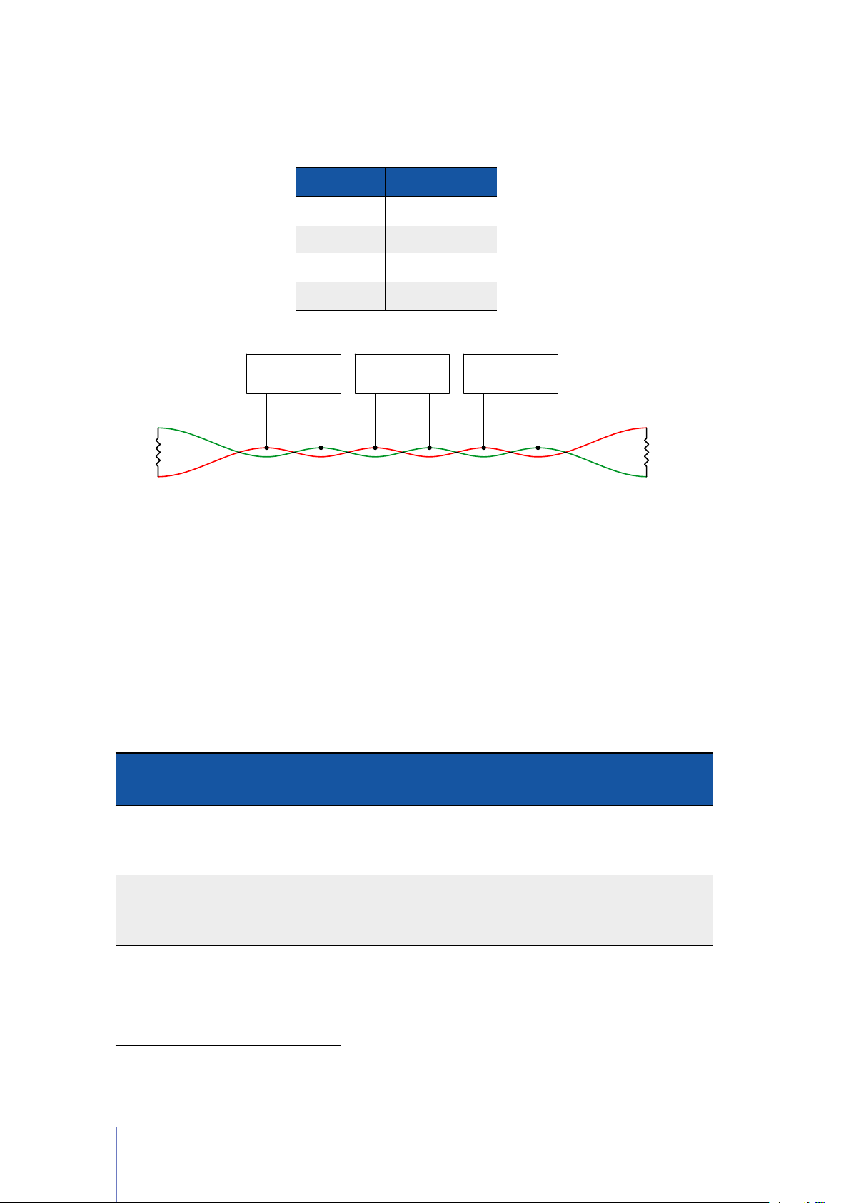
Please pay particular attention when wiring CANopen®connection: at both ends
DEVICE 1 DEVICE 2 DEVICE 127
120 Ohm
120 Ohm
there must be a 120Ω resistor and the bus length must be the following:
BI T R ATE BU S L ENGTH
1 Mbit/s 25 m
500 Kbit/s 100 m
250 Kbit/s 250 m
125 Kbit/s 100 m
2.3.5 RS232 Mode
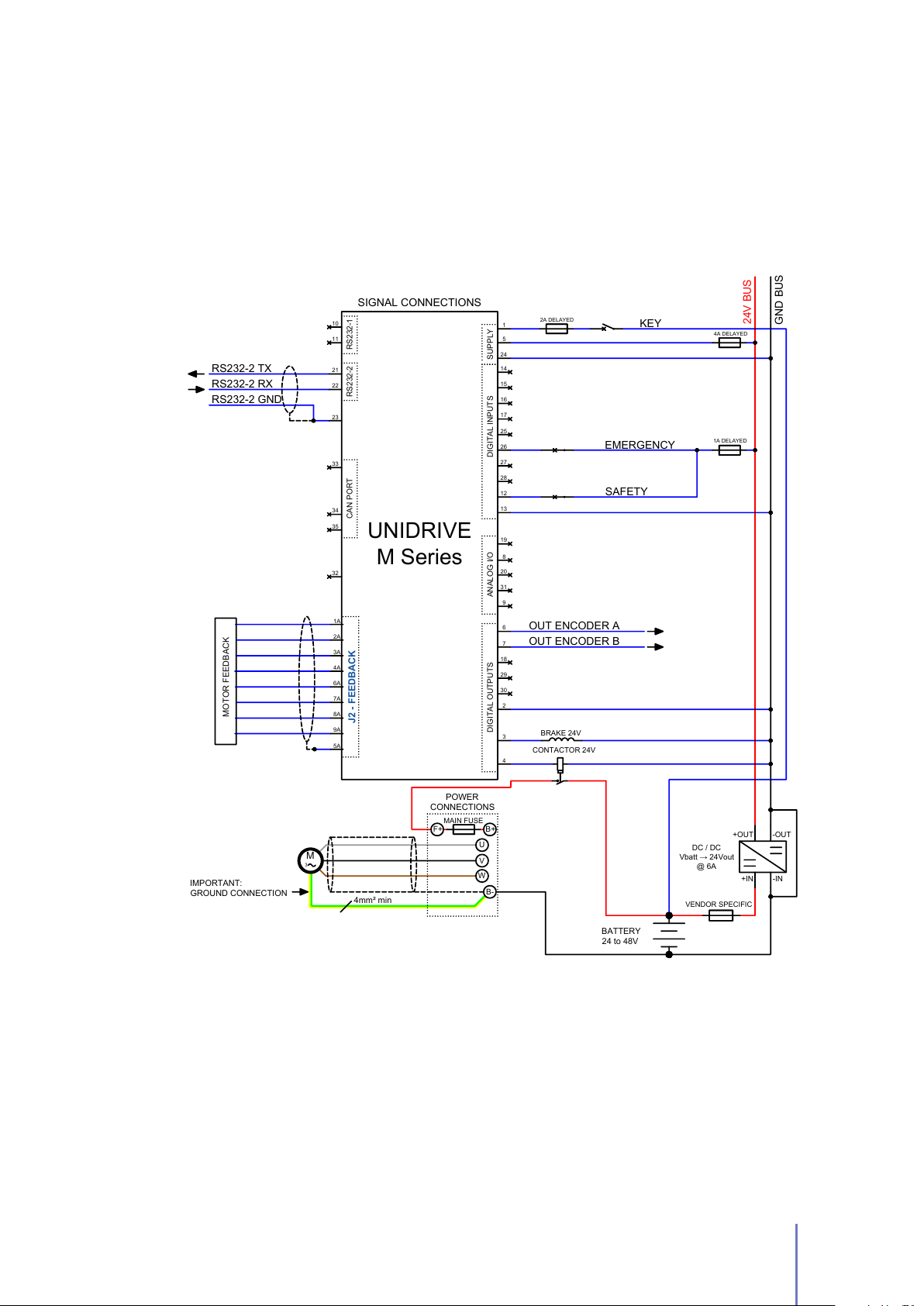
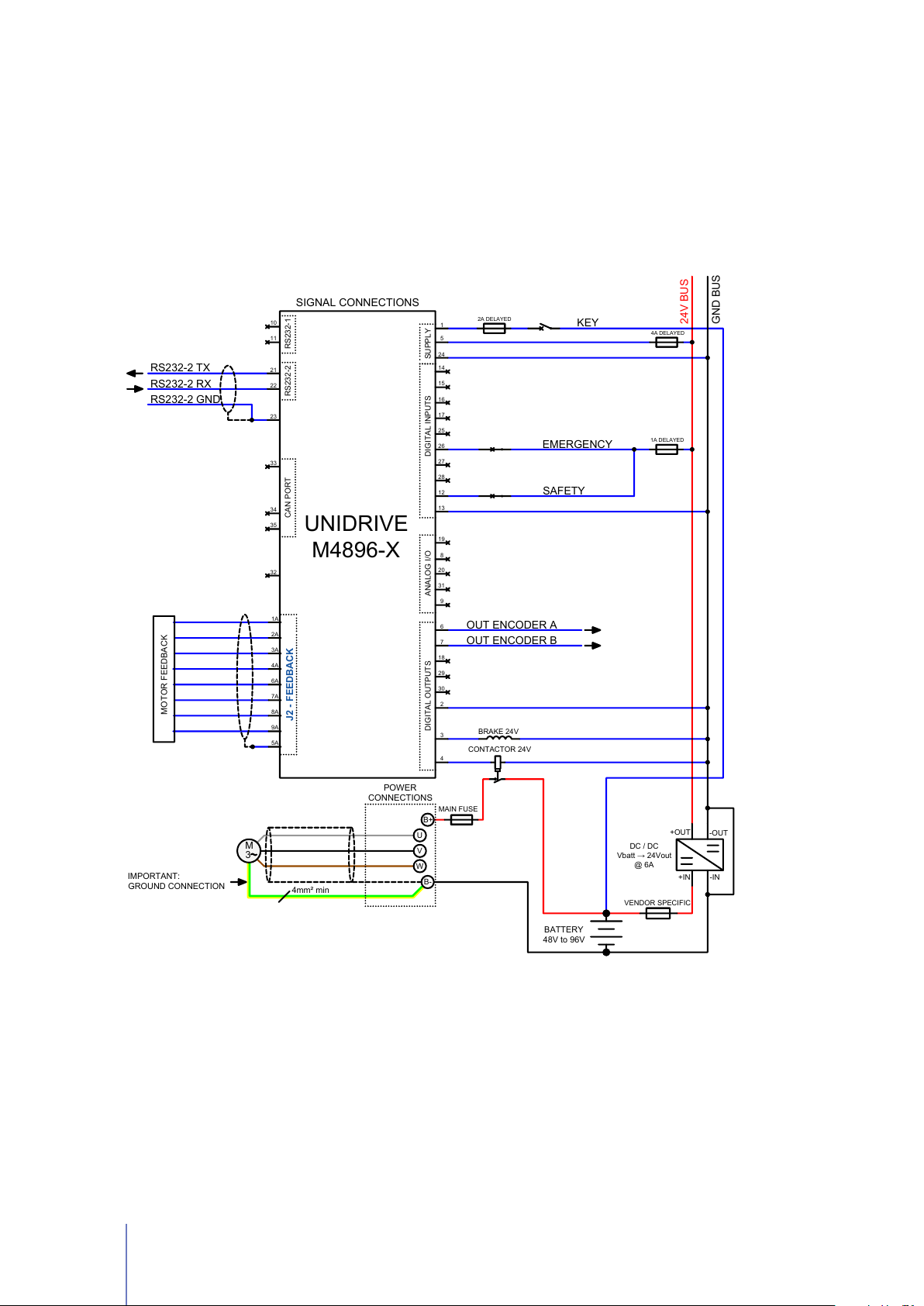
The RS232 Mode allows you to drive your motor via Telemetry Panel (See Chapter
4) or send the control commands2to the UNIDRIVE through the RS232 protocol.
This operating mode can be useful for testing your motor, without worrying about
other devices (e.g: potentiometer) or other controllers (e.g: PLC) (See Section
4.2.4). See Figure 2.12 for wiring diagrams for this operating mode and Table 2.9
for a description of inputs and outputs.
Table 2.9: UNIDRIVE I/O definitions for RS232 Mode.
I/O
PI N
TY PE
26 IN6
29 OUT4 ALARM
NA ME DE SCRIPTIO N
Emergency input should always be
EMERGENCY
supplied, otherwise UNIDRIVE stops
motor rotation and unlocks motor brake.
Alarm output, it changes its current state
whenever an alarm is present. See Section
3.4.1, Pag. 41
Mandatory
2
For further information, see UNIDRIVE - RS232 Communication Protocol document
30 Chapter 2 Installation and Wiring
Page 35
RS232 Mode - Wiring Diagram
BRAKE 24V
32
33
34
35
1
14
15
16
17
28
25
26
27
8
20
3
7
6
29
30
18
4
9
31
2
5
24
24V BUS
GND BUS
SIGNAL CONNECTIONS
KEY
EMERGENCY
2A DELAYED
4A DELAYED
+IN
-IN
+OUT
-OUT
CAN PORT
DIGITAL OUTPUTS
SUPPLY
1A DELAYED
OUT ENCODER A
OUT ENCODER B
POWER
CONNECTIONS
U
V
W
MAIN FUSE
F+ B+
RS232-2 TX
RS232-2 RX
RS232-2 GND
11
10
21
22
23
RS232-2 RS232-1
19
12
DIGITAL INPUTS
ANALOG I/O
SAFETY
13
4mm² min
M
3
B-
1A
2A
3A
4A
6A
7A
8A
9A
5A
J2 - FEEDBACK
MOTOR FEEDBACK
CONTACTOR 24V
BATTERY
24 to 48V
VENDOR SPECIFIC
DC / DC
Vbatt → 24Vout
@ 6A
IMPORTANT:
GROUND CONNECTION
UNIDRIVE
M Series
Figure 2.12:
Type - to your system in RS232 Mode
The wiring diagram to connect your
UNIDRIVE H Series
- except the M4896-X
2.3 Standard Wiring Diagrams and Wiring Instructions 31
Page 36
RS232 Mode - Wiring Diagram [M4896-X Type]
BRAKE 24V
32
33
34
35
1
14
15
16
17
28
25
26
27
8
20
3
7
6
29
30
18
4
9
31
2
5
24
24V BUS
GND BUS
SIGNAL CONNECTIONS
POWER
CONNECTIONS
KEY
EMERGENCY
2A DELAYED
4A DELAYED
B+
U
V
W
+IN
-IN
+OUT
-OUT
CAN PORT
DIGITAL OUTPUTS
MAIN FUSE
SUPPLY
1A DELAYED
OUT ENCODER A
OUT ENCODER B
RS232-2 TX
RS232-2 RX
RS232-2 GND
11
10
21
22
23
RS232-2 RS232-1
19
12
DIGITAL INPUTSANALOG I/O
SAFETY
13
B-
3
M
1A
2A
3A
4A
6A
7A
8A
9A
5A
J2 - FEEDBACK
MOTOR FEEDBACK
UNIDRIVE
M4896-X
CONTACTOR 24V
VENDOR SPECIFIC
DC / DC
Vbatt → 24Vout
@ 6A
BATTERY
48V to 96V
IMPORTANT:
GROUND CONNECTION
4mm² min
Figure 2.13:
RS232 Mode
The wiring diagram to connect your UNIDRIVE
M4896-6-x
to your system in
32 Chapter 2 Installation and Wiring
Page 37
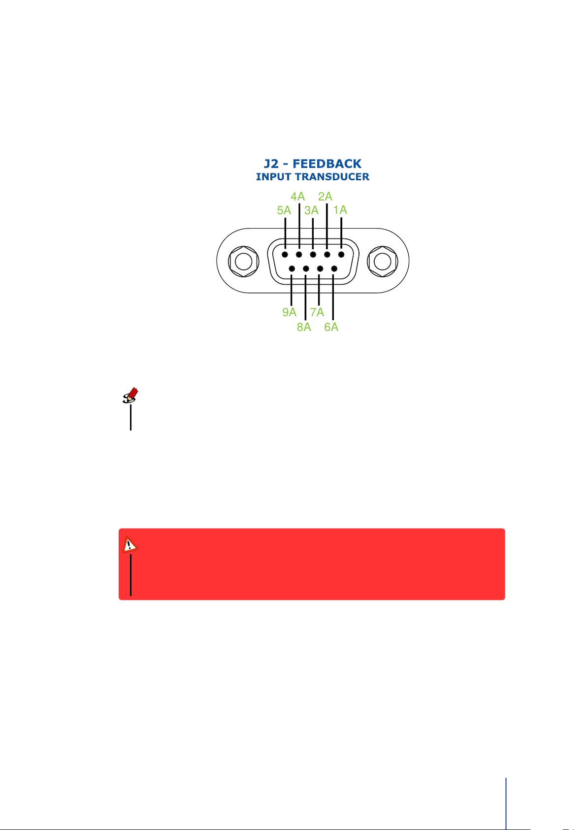
2.4 Feedback Connector
5A
4A
3A
2A
1A
6A
7A
8A
9A
A female 9-pin connector (
board to the UNIDRIVE (See Figure 2.14).
Figure 2.14: Pin Assignments of the J2 - FEEDBACK connector.
J2 - FEEDBACK
) is provided to connect the feedback
Note
The pinout descriptions of
feedback board mounted on your motor.
J2 - FEEDBACK
connector depends on the type of
It’s essential for the proper functioning of the feedback system that the feedback
cable was constructed specifically for the feedback type mounted on your motor.
We
highly recommend
of signals transmitted.
choosing a
good quality cable
in accordance with the type
Warning
Make sure when you connect the high-powered connections that the feedback
cable passes as far as possible from the power cables, and them are not located
close to each other, in order to avoid electromagnetic interference.
2.4 Feedback Connector 33
Page 38
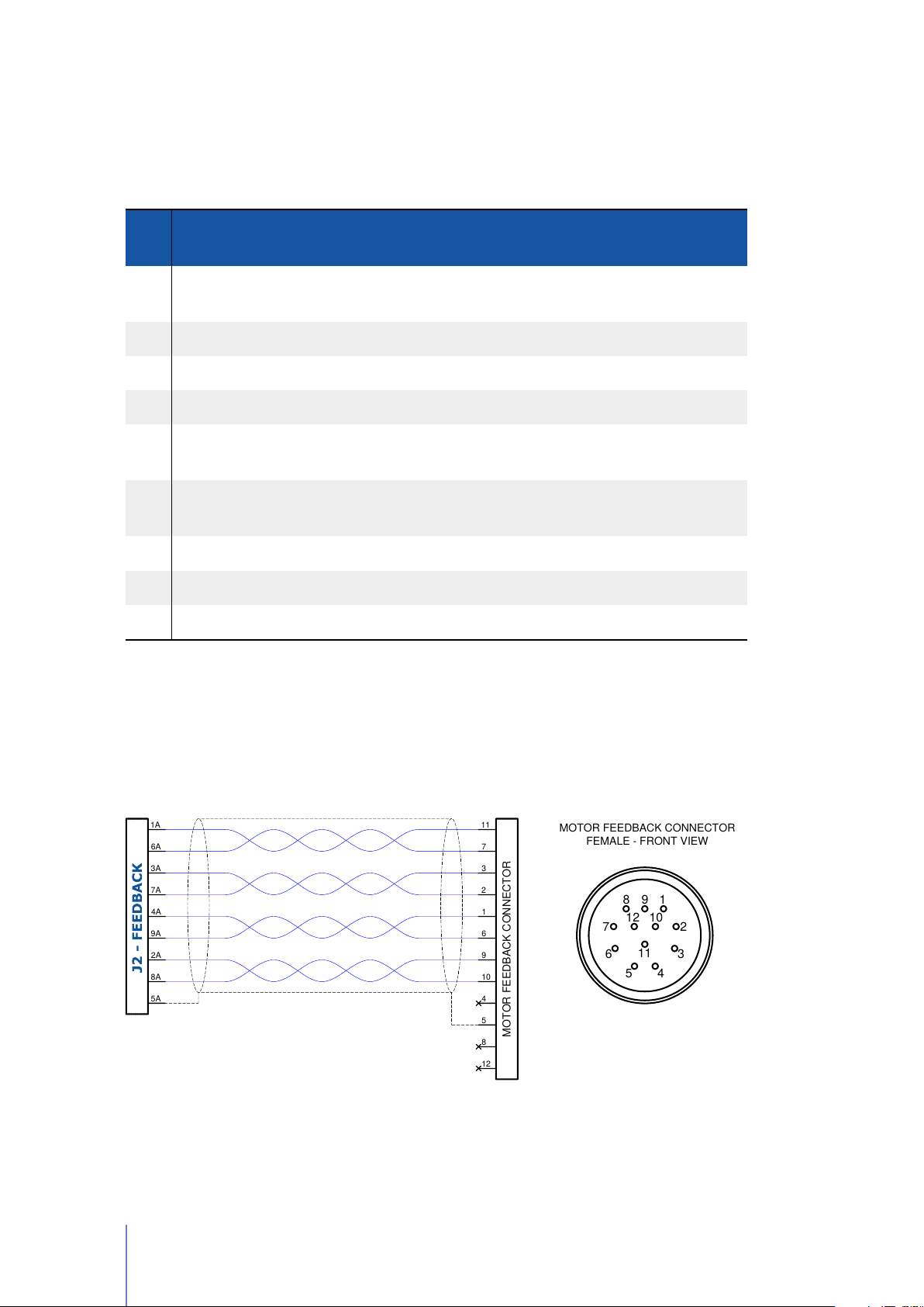
2.4.1 Resolver
5A
MOTOR FEEDBACK CONNECTOR
4
5
8
12
1A
2A
3A
4A
6A
7A
8A
9A
11
9
3
1
7
2
10
6
8 9 1
7
6
5
2
3
4
11
12 10
MOTOR FEEDBACK CONNECTOR
FEMALE - FRONT VIEW
Table 2.10:
Pinout Description of the
J2 - FEEDBACK
connector (See Figure 2.14) to
connect a Resolver to your UNIDRIVE.
OP ERATI NG
PI N I/O TYPE DE SCRIPTIO N
RA NGE
1A
2A THERMAL Temperature sensor / Optional
3A SIN- Negative Sine From -4 to +4 V Mandatory
4A COS- Negative Cosine From -4 to +4 V Mandatory
5A
6A
7A SIN+ Positive Sine From -4 to +4 V Mandatory
8A THERMAL Temperature sensor / Optional
DRIVING
The negative Driving signal From -5 to +5 V Mandatory
SIGNAL -
INNER
Connect to the cable shield / Mandatory
SHIELD
DRIVING
The positive Driving signal From -5 to +5 V Mandatory
SIGNAL +
a
a
9A COS+ Positive Cosine From -4 to +4 V Mandatory
a
Mandatory
only if you’ve selected Thermistor, KTY83/122 or KTY84/130 as Temperature probe type
(See Pag. 49)
For example, if your motor has a M12 feedback motor connector:
Figure 2.15:
Wiring Diagram to connect your
has a M12 feedback motor connector.
34 Chapter 2 Installation and Wiring
Resolver
board to UNIDRIVE if your motor
Page 39
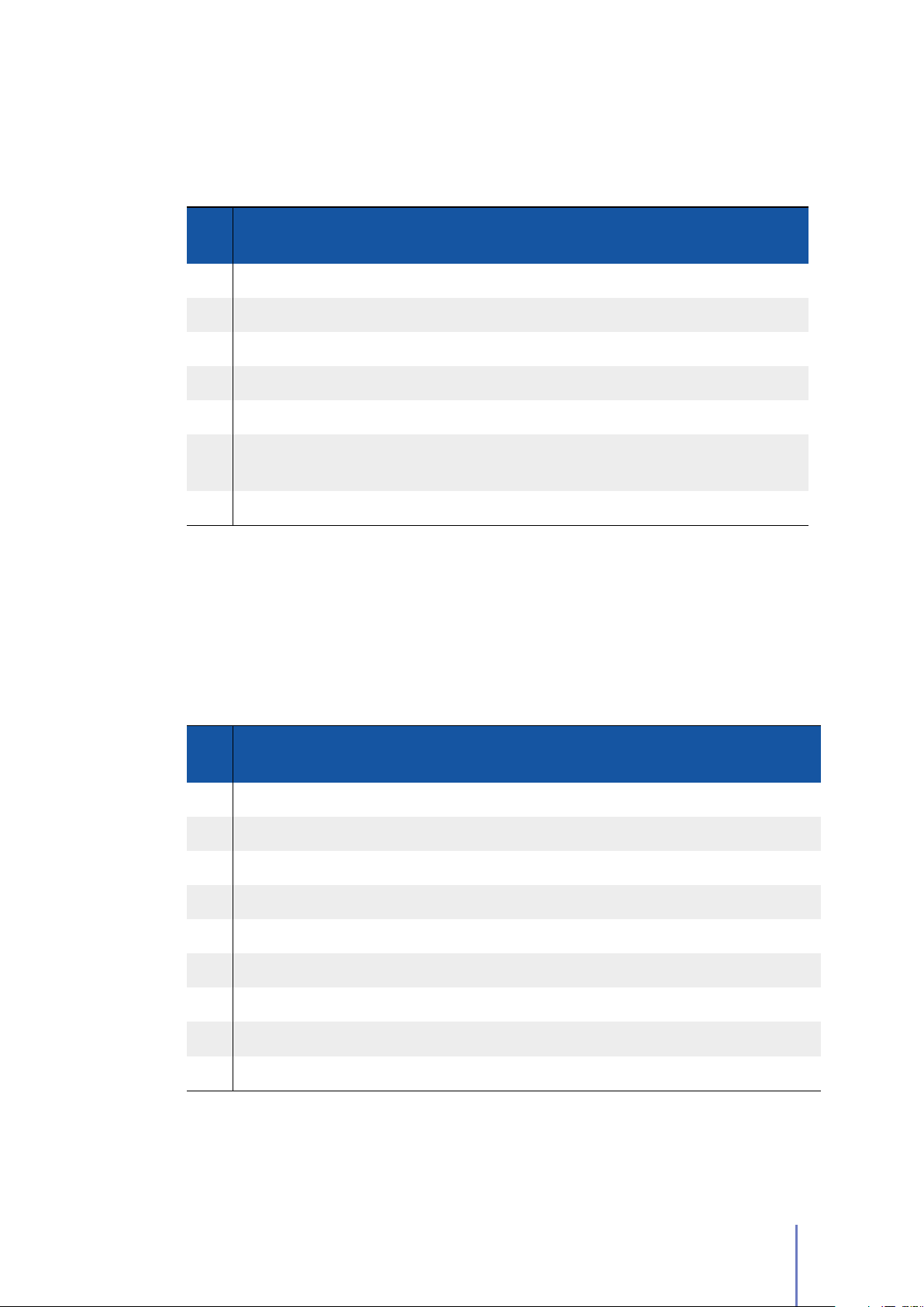
2.4.2 SinCos Encoder
Table 2.11:
Pinout Description of the
J2 - FEEDBACK
connector (See Figure 2.14) to
connect a SinCos Encoder to your UNIDRIVE.
OP ERATI NG
PI N I/O TYPE DE SCRIPTIO N
RA NGE
1A +5 V SinCos Supply V = +5 V Mandatory
2A SIN Sine Signal From -5 to +5 V Mandatory
3A COS Cosine Signal From -5 to +5 V Mandatory
4A THERMAL Temperature sensor / Optional
6A GND Common Ground / Mandatory
7A
9A THERMAL 2 Temperature sensor / Optional
a
Mandatory
(See Pag. 49)
INNER
Connect to the cable shield / Mandatory
SHIELD
only if you’ve selected Thermistor, KTY83/122 or KTY84/130 as Temperature probe type
a
a
2.4.3 Hall Sensor
Table 2.12:
connect a Hall Sensor to your UNIDRIVE.
PI N I/O TYPE DE SCRIPTIO N
1A +8V Hall sensors supply / Mandatory
2A THERMAL Temperature sensor / Optional
3A H3 Hall Sensor 3
4A H2 Hall Sensor 2
5A H1 Hall Sensor 1
6A GND Hall Sensor Ground / Mandatory
7A GND Hall Sensor Ground / Mandatory
8A THERMAL Temperature sensor / Optional
9A GND Hall Sensor Ground / Mandatory
a
Mandatory
(See Pag. 49)
Pinout Description of the
only if you’ve selected Thermistor, KTY83/122 or KTY84/130 as Temperature probe type
J2 - FEEDBACK
connector (See Figure 2.14) to
OP ERATI NG
RA NGE
From +5 to +24 V
From +5 to +24 V
From +5 to +24 V
Mandatory
Mandatory
Mandatory
a
a
2.4 Feedback Connector 35
Page 40

36
Page 41

Configuration
This chapter covers what you need to know to configure your UNIDRIVER M Series
via Telemetry Panel.
Warning
This part of the manual assumes that UNIDRIVE was wired up correctly by
following methods described in Chapter 2.
Telemetry Panel allows the adjustment of a wide range of parameters through the
USB port in order to customize the vehicle’s performance characteristics. To install
Telemetry Panel you would simply double-click on Setup.exe file and following the
instructions in the setup assistant.
After the installation, you can select your preferred language1and temperature scale
- Celsius or Fahrenheit - from the list that appears under Setup menu.
3
Note
This Reference Manual is written for Telemetry Panel version
and is not suitable for earlier software and firmware versions.
3.1 Software Overview
Software is organized in tabs according to the main functions:
Telemetry
Programmable Parameters
Advanced
In this tab real-time telemetry data are displayed in easy-to-read format.
You can also look at variables over time, both in graphical form and as data
files.
main parameters of UNIDRIVE, import and export them in CFG format.
Advance Tab includes some more programmable parameters to control
your driver.
2.4.6.8
In Programmable Parameters tab you can configure
or later,
1
In order to display Chinese Unicode characters, user needs a Unicode Window or
Unicode-compatible controls. User may also need to ensure that his Regional Settings are set up to
support far eastern text/fonts.
37
Page 42
Autotuning
Resolver/SinCos can be estimated in Autotuning tab.
The gain parameters for closed-loop current control and offset value of
Car EV Mode
see telemetry data for EV mode.
Steering Mode
more information, see the Steering Mode manual.
In this tab you can configure specific programmable parameters and
Steering Mode is an advanced operating mode of UNIDRIVE. For
3.2 Connect UNIDRIVE to your PC
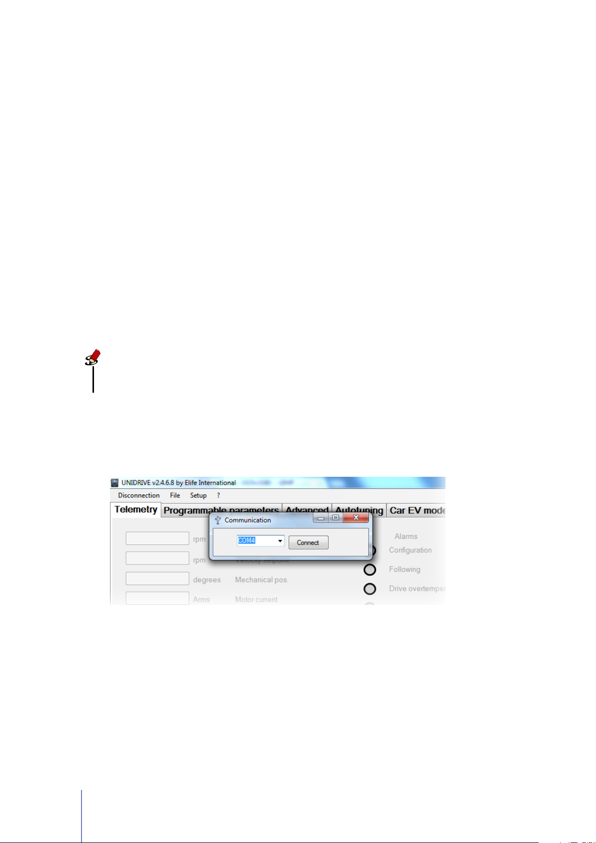
In order to connect your UNIDRIVE to Telemetry Panel, you should connect it to
PC and wait for USB port recognition. After USB port recognition, you can launch
Telemetry Panel and click on Connection menu (Figure 3.1).
Connect button permits to start communication toward the select USB port.
Note
Telemetry panel automatically creates a list of available USB port. It’s then
necessary to choose the suitable port where UNIDRIVE is connected.
After connection, Telemetry Panel loads parameters from UNIDRIVE allowing you to
change them.
Figure 3.1: Connect your UNIDRIVE to Telemetry Panel by USB port
3.3 Import and Export Parameter Values
After connecting your UNIDRIVE to PC you can easily import or export (save)
parameter values from and to .cfg file by Telemetry Panel.
38 Chapter 3 Configuration
Page 43
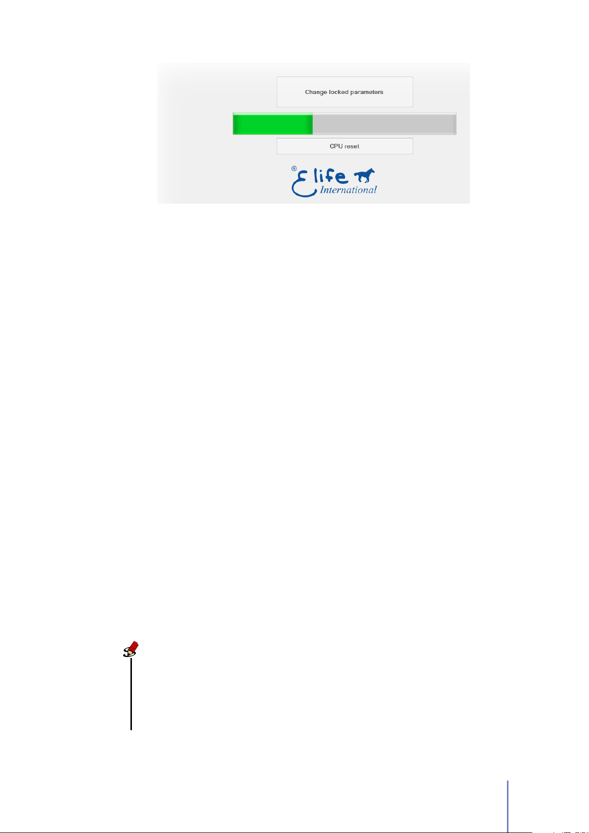
Figure 3.2:
file to UNIDRIVE.
•
When the progress bar is running, Telemetry Panel downloads data from .cfg
In oder to import parameters from file and download them on to UNIDRIVE:
1. Move to Programmable Parameters tab.
2. Select the File Menu and click on Open option.
3.
Select the desired .cfg file and wait for the progress bar to get completely
green (Figure 3.2).
•
Parameter values can also be exported to a .cfg file:
1. Move to Programmable Parameters tab.
2. Select the File menu and click on Save.
3. Enter a descriptive name in the file name box and click Save.
3.4 Change Programmable Parameters
Programmable Parameters enables you to customize vehicle’s performance characteristics
to best fit your needs.
Note
Telemetry Panel automatically recognizes your UNIDRIVE type and the
feedback input (Resolver,Hall Sensor,SinCos Encoder,etc) that you’ve installed
on your system. The
disabled
mode selected.
are not interesting for your model connected or for the operating
Parameters
that have their textboxes
3.4 Change Programmable Parameters 39
empty and
Page 44
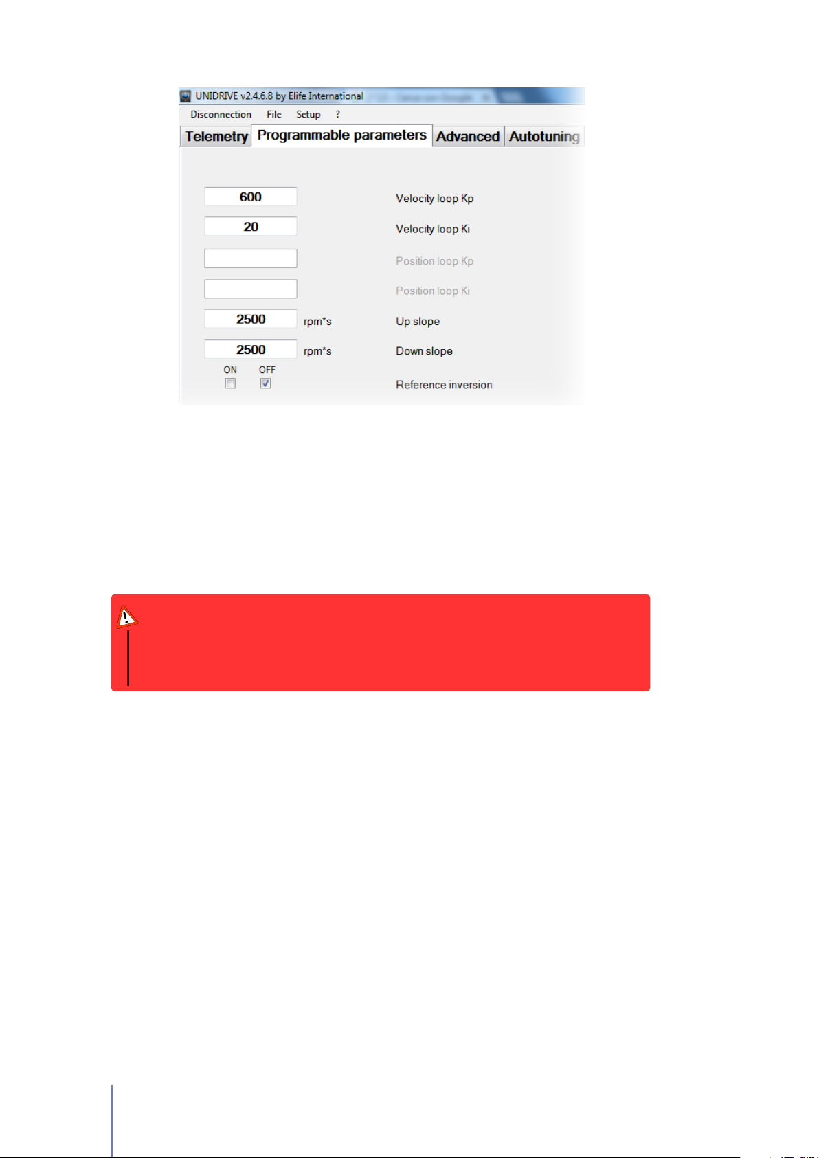
Figure 3.3:
programmable parameters and set the operating mode.
In Programmable Parameters tab (Figure 3.3) you can read and change the main
programmable parameters and set the operating mode of UNIDRIVE (Standalone,PLC,etc).
After connecting your UNIDRIVE to PC and
changed in Programmable Parameters tab.
Programmable Parameters tab allows you to read and change the main
stopping the motor
Warning
We recommend saving preset programmable parameters to .cfg file before
changing them, so that you can restore the preset parameters if necessary. See
Section 3.3
3.4.1 Operating Mode and Controller Parameters
, the values can be
Velocity Loop Kp
than 4096. This parameter is also programmable by CANopen®protocol.
Velocity Loop Ki
1024. This parameter is also programmable by CANopen®protocol.
Position loop Kp
than 16384. This parameter is also programmable by CANopen®protocol.
Position loop Ki
128. This parameter is also programmable by CANopen®protocol.
40 Chapter 3 Configuration
Proportional gain for closed-loop speed control, it must be less
Integral gain for closed-loop speed control, it must be less than
Proportional gain for closed-loop position control, it must be less
Integral gain for closed-loop position control, it must be less than
Page 45
Note
The gain parameters for closed-loop position control will only processed
if configuration is CANopen®and mode of operation is Interpolated
Position Mode.
Speed closed loop This text box is only valid for DC motor.
Feedback inversion This text box is only valid for DC motor.
Encoder inversion This text box is only valid for DC motor.
NH Alarm Output
If checked OFF, alarm output is normally low (NL), else it is
normally high (NH).
Configuration
This option set the operating mode of UNIDRIVE. The allowed
values for this parameter are Standalone,CAN Network,PLC,EV and RS232 (in
Speed or Torque Mode).
Warning
UNIDRIVE must be wired up correctly according to the operating mode
selected. See Chapter 2.
Max drive temperature
At this drive temperature drive must rise "Drive over-temperature"
alarm.
UN IT MIN VALUE MA X VALUE
◦
C 80 110
(◦F ) (176) (230)
Following error delay
120 %
of the target speed over the set time, UNIDRIVE stops the motor with
When the detected speed is less than
80 %
following error alarm. This parameter is also programmable by CANopen
protocol.
UN IT MIN VALUE MA X VALUE
s 0 15
3.4 Change Programmable Parameters 41
or more than
®
Page 46
3.4.2 Motor and Acceleration Parameters
Up slope
Lower values indicate a longer acceleration time and a more gradual
departure, while bigger values indicate a faster acceleration. The implemented
ramp is linear. This parameter is also programmable by CANopen®protocol.
UN IT MIN VALUE MA X VALUE STEP
rpm/s 500 35 · 10
Down slope
arrest, while bigger values indicate a faster deceleration. The implemented
ramp is linear. This parameter is also programmable by CANopen®protocol.
Lower values indicate a longer deceleration time and a more gradual
5
500
UN IT MIN VALUE MA X VALUE STEP
rpm/s 500 35 · 10
Reference inversion It allows you to invert the stated direction.
Max motor speed
direction. It is used to protect the motor and must be taken from the motor
datasheet. This parameter is also programmable by CANopen®protocol.
It indicates the maximum allowed speed for the motor in either
5
500
UN IT MIN VALUE MA X VALUE
rpm 0 7000
Max speed at slow mode
in either direction when Slow or ECONOMY mode is selected.
Backward maximum speed
direction. It’s only processed for EV configuration.
UN IT MIN VALUE MA X VALUE
rpm 0 7000
3.4.3 Throttle Parameters
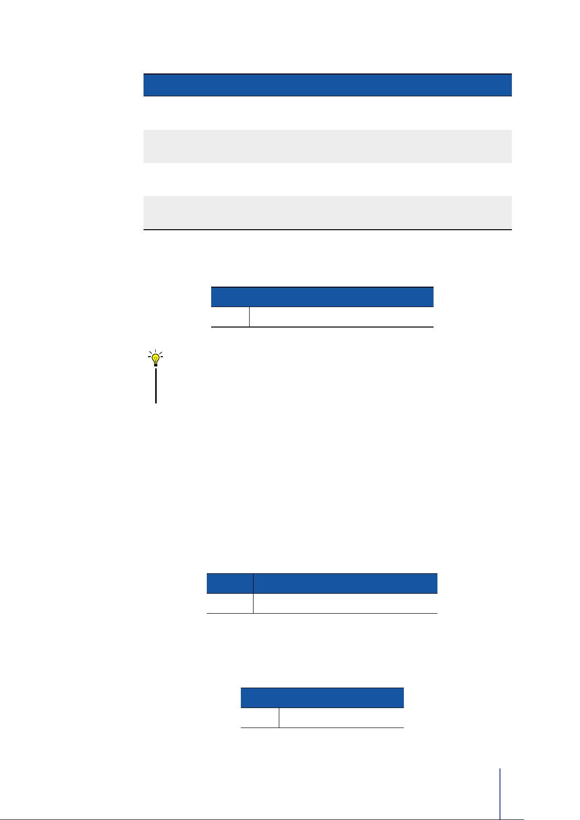
Analogic input
process the speed potentiometer. It is processed only for PLC, EV and Standalone.
This parameter describes the analog operational mode used to
It indicates the maximum allowed speed for the motor
UN IT MIN VALUE MA X VALUE
rpm 0 7000
It indicates the backward allowed speed for the opposite
42 Chapter 3 Configuration
Page 47
VALUE DE SCRIPTIO N
0 - 10
0-5 - 10
0 - 5
0-2.5 - 5
Deadband
It is the percentage of deadband for potentiometer. Increasing deadband
enlarges the stop range.
Tips and Advice
This parameter is particularly useful for potentiometers that can’t regularly go
back to a clear idle point. Deadband must be wide enough to guarantee the
transfer of driver to idle when accelerator mechanism is released.
Direction inversion is realized through direction digital input
(DIR/FORWARD).
When the potentiometer value is between5and
positive. When it is less than 5 V speed reference is negative.
Direction inversion is realized through direction digital input
(DIR/FORWARD)
When the potentiometer value is between
positive. When it is less than 2.5 V speed reference is negative
2.5
and
10 V
speed reference is
5 V
speed reference is
UN IT MIN VALUE MA X VALUE
% 0 50
3.4.4 CANopen®Parameters
Size Indicator
the last four bytes of the communication.
CANopen®address
unique identifier for each device. When this parameter value is changed, device
will be automatically reset.
CANopen®baudrate
PLC and the device. When this parameter value is changed, device will be
automatically reset.
if checked ON, the size of the data to be transmitted is specified in
It’s the CANopen®node-ID for the device that is the network-wide
UN IT MIN VALUE MA X VALUE
integer 0 127
The baudrate for the CANopen®communication between
UN IT ALLOWED VALUES
Kbps 1000 - 500 - 250
3.4 Change Programmable Parameters 43
Page 48

Note
The CANopen®values will only processed if UNIDRIVE works in CAN
Network or PLC configuration.
3.4.5 Locked Parameters
In Programmable Parameters tab there are a few programmable parameters which
their text-boxes are disabled but filled with a value (Figure 3.4). You can unlock
them and change their value.
Warning
These parameters are critical for the correct function of UNIDRIVE. You should
change these parameters carefully and only if necessary.
In order to change these parameters:
1. Click on Change Locked Parameters button.
2. Insert the password: 8192
After unlocking, you will be able to change:
Current Loop Kp
than 1024. This parameter is also programmable by CANopen®protocol.
Current loop Ki
512. This parameter is also programmable by CANopen®protocol.
Proportional gain for closed-loop current control; it must be less
Integral gain for closed-loop current control; it must be less than
Tips and Advice
The Kp and Ki values can be calculated by using Telemetry Panel. See
Section 3.5.1
Motor poles
datasheet.
It indicates the number of motor poles and must be taken from motor
UN IT ALLOWED VALUES
even integer 4 - 6 - 8 - 10 - 44
Phase Advance
improve efficiency and torque performance for brushless machines. This
44 Chapter 3 Configuration
Phase advance techniques provide field-weakening operation to
Page 49
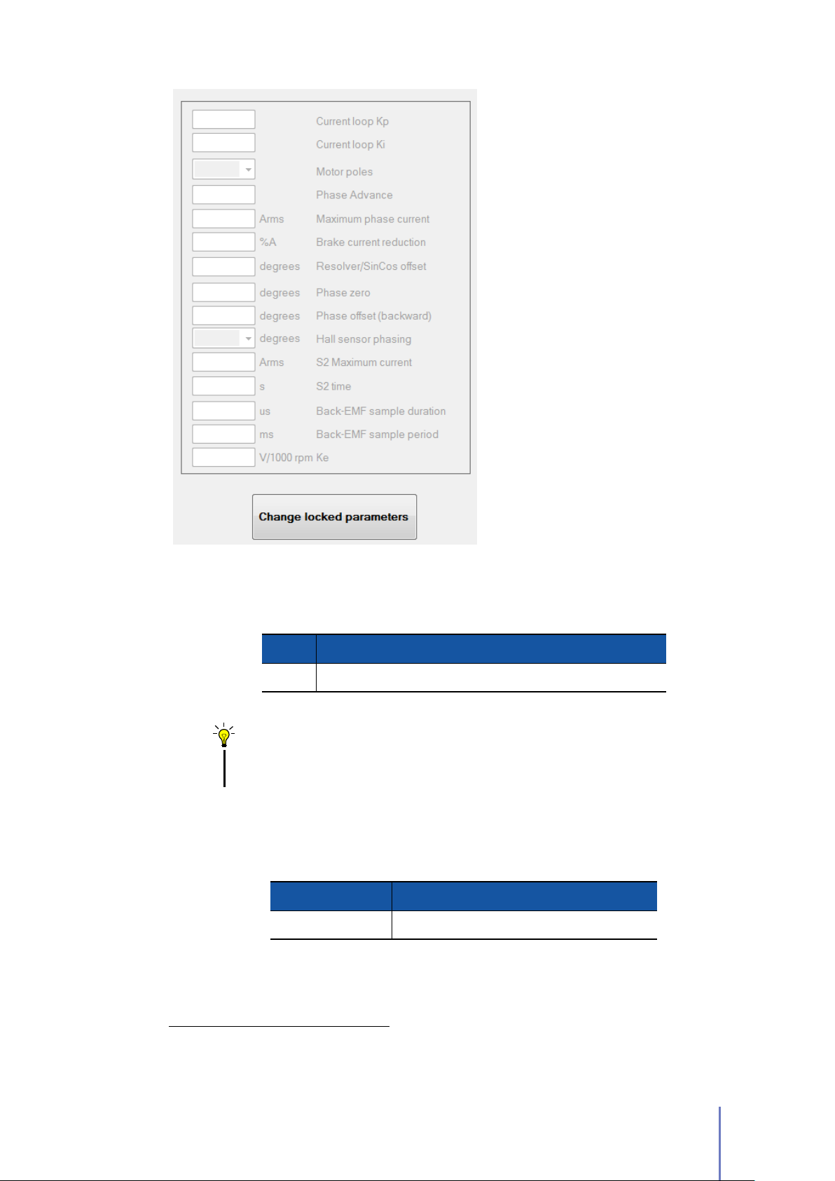
Figure 3.4:
Programmable tab there are
some parameters locked. You can
unlocked them after clicking on
Change Locked Parameters button.
In Parameters
parameter indicates the phase advance angle with respect to back-EMF of
phase current.
UN IT MIN VALUE MA X VALUE STE P
a.u. 0 32 1
Tips and Advice
Motors whose inductance value is high might require a high value of
phase advance angle.
Maxiumum phase current
It shows the maximum permissible current in the motor.
This parameter is also programmable by CANopen®protocol.
UN IT MIN VALUE MAX VALUE
Amperes RMS 0 Max
Brake current reduction
It is the reduction of current and voltage applied to motor.
It’s useful to reduce thermal dissipation due to service brake activation. It
2
The maximum peak output current depends on the UNIDRIVE model installed.
3.4 Change Programmable Parameters 45
2
Page 50
intervenes only after one minute from brake activation. Its value must be less
than 50%.
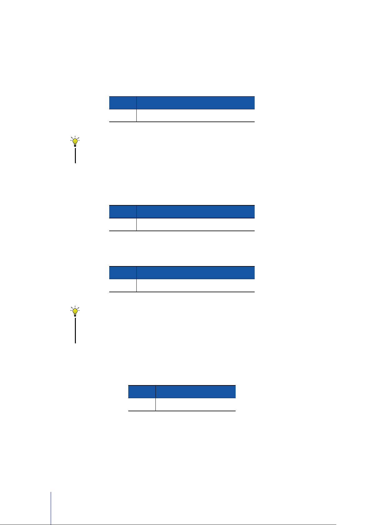
Resolver/SinCos offset
SinCos Encoder. Offset to sum to resolver/encoder position.
This parameter is only valid for Motor with Resolver or
UN IT MIN VALUE MAX VALUE
degree 0 359.99
Tips and Advice
Resolver/SinCos offset value can be calculated by using Telemetry Panel.
See Section 3.5.2
Phase zero
applying forward direction.
This parameter is only valid for Hall sensor drive. It must be chosen
UN IT MIN VALUE MAX VALUE
degree 0 359.99
Phase offset(backward)
be chosen after precisely setting of phase zero, applying backward direction.
This parameter is only valid for Hall sensor drive. It must
UN IT MIN VALUE MAX VALUE
degree 0 359.99
Tips and Advice
For phase zero and phase offset value we suggest to start with a small
value (e.g. 0.05) and increase by 5 until motor consumption and
sinewave are at their best.
Hall sensor phashing
the relative position of Hall sensors.
This parameter is only valid for Hall sensor drive. It indicates
UN IT ALLOWED VALUES
degree 60 - 120
S2 Maximum current This text box is only valid for DC motor.
S2 time This text box is only valid for DC motor.
Back-EMF sample duration This text box is only valid for DC motor.
46 Chapter 3 Configuration
Page 51
Back-EMF sample period This text box is only valid for DC motor.
Ke This text box is only valid for DC motor.
3.4.6 Advanced Parameters
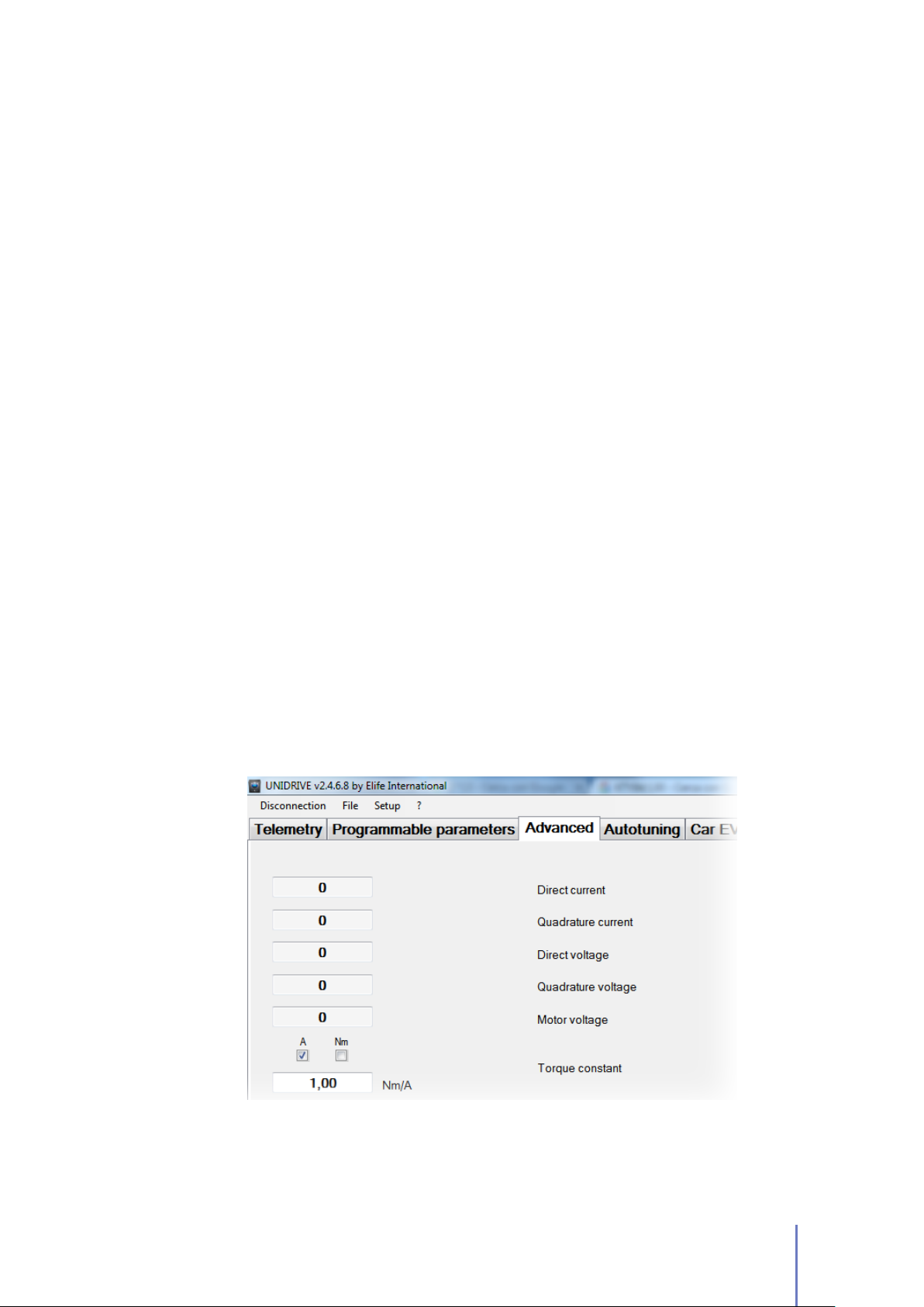
Adavanced tab allows you to read and change some more programmable parameters
(Figure 3.5).
Some information about UNIDRIVE - such as
customer code, etc - and CANopen®parameters are displayed in this tab.
It’s possible to read the following telemetry data:
firmware version
, serial number,
Direct current
It shows the actual value of direct current, that is one output for
Park transform (stator current component proportional to the flux). Motor is
working fine if it is about 0. It is given in arbitrary unit.
Quadrature current
It shows the actual value of quadrature current, that is one
output for Park transform (stator current component proportional to the rotor
torque). It is given in arbitrary unit.
Direct voltage
It shows the actual value of direct voltage, that is one output for PI
closed-loop. It is given in arbitrary unit.
Quadrature voltage
It shows the actual value of quadrature voltage, that is one
output for PI closed-loop. It is given in arbitrary unit.
Figure 3.5:
parameters.
In Advanced tab is possible to read and change some more programmable
3.4 Change Programmable Parameters 47
Page 52
Motor voltage
It shows the actual value of motor voltage. It is given in arbitrary
unit.
In Advanced tab you can also
modify
the following programmable parameters:
Torque constant
AmperestoN·m
This variable permits to convert motor torque current from
. This parameter is also programmable by CANopen®protocol.
UN IT MIN VALUE MA X VALUE
N·m/A 0.00 10.00
Analog output
ANALOG OUT (
This parameter allows you to set a desired value of voltage to
PI N 9
Panel".
UN IT MIN VALUE MA X VALUE
V olt 0 10
Analog output function
output
) output if
Analog output function
is set as "Telemetry
You can choose the operating mode of the ANALOG OUT
VALUE DESCRIP TION
Telemetry Panel
Motor speed
Brake fault alarm
When turned OFF, UNIDRIVE won’t stop the motor nor inform
about a brake failure.
Supply fault alarm
When turned OFF, UNIDRIVE won’t stop the motor nor inform
about a power supply relay failure.
Lower battery dinamic decrease
UNIDRIVE decrease automatically the speed in order to extend the battery life.
Overtravel warning
When turned ON, UNIDRIVE will stop the motor when one of
two over-travel inputs will get high. Only for PLC Mode
The output voltage of the ANALOG OUTPUT is equal to Analog
output value set.
In this operating mode the voltage output of the ANALOG OUT
varies linearly with the motor speed. From
speed is
motor Speed (See Section 3.4.2).
0 rpmto10 V
when the motor speed is equal to
0 V
if it turned ON, when the battery is being consumed
when the motor
Max
48 Chapter 3 Configuration
Page 53
Emergency input fault
If emergency input fault is ON, when emergency input gets
low motor will stop with alarm; otherwise motor will only stop with ramp.
Alarm output N.L. logic
This textbox is disabled for UNIDRIVE H Series in standard
operating mode.
Emergency Slope
This parameter configures alarm deceleration, lower values
indicate a longer deceleration time and a more gradual arrest, while bigger
values indicate a faster deceleration. The implemented ramp is linear. This
parameter is also programmable by CANopen®protocol.
UN IT MIN VALUE MA X VALUE STEP
rpm/s 500 35 · 10
Temperature probe type
From this combobox, user can select the correct PTC type
from Thermostat, KTY83/122, KTY84/130 or none.
5
500
Note
If KTY83/122 or KTY84/130 is chosen, it will also be possible to read
motor temperature from Telemetry tab.
Maximum motor temperature
At this temperature drive must rise Motor overtemperature
alarm.
UN IT MIN VALUE MA X VALUE
◦
C 0 255
(◦F ) (32) (491)
Encoder resolution This parameter is only available for DC motors.
Mechanical reducer This parameter is only available for DC motors.
Encoder resolution This parameter is only available for DC motors.
Potentiometer Supply
You can select the output voltage of
PWR POT
8) in according to the throttle characteristics.
UN IT ALLOWED VALUES
output (PIN
V olt 5 - 10
3.4 Change Programmable Parameters 49
Page 54
TPD02 transmission type
processed if configuration is CANopen®and can be programmable by CANopen
protocol also.
It sets the type of transmission for TPDO2. It’s only
UN IT MIN VALUE MA X VALUE
integer 1 255
®
RPD02 transmission type
processed if configuration is CANopen®and can be programmable by CANopen
protocol also.
It sets the type of transmission for RPDO2. It’s only
UN IT MIN VALUE MA X VALUE
integer 1 255
In Advanced tab there is also
current alarms.
Reset Alarm
button which allows you to reset all
3.5 Auto-tuning UNIDRIVE Parameters
Telemetry Panel includes two functions which help you to estimate approximate
value of the following parameters:
•
The gain parameters for closed-loop current control.
®
•
The Offset Resolver/SinCos to sum to resolver/encoder position.
Warning
Please note that the suggested parameters are only a point of departure. They
must be adjusted according to system and you should run the motor only after
checking them.
3.5.1 Gain Parameters for closed-loop Current Control
In order to calculate the value of Kp and Ki for closed-loop current control you need
two basic motor information: Winding resistance and Winding inductance.
You should normally find these parameters on data-sheet of your motor, otherwise
you must ask the motor manufacturer to provide these data.
50 Chapter 3 Configuration
Page 55
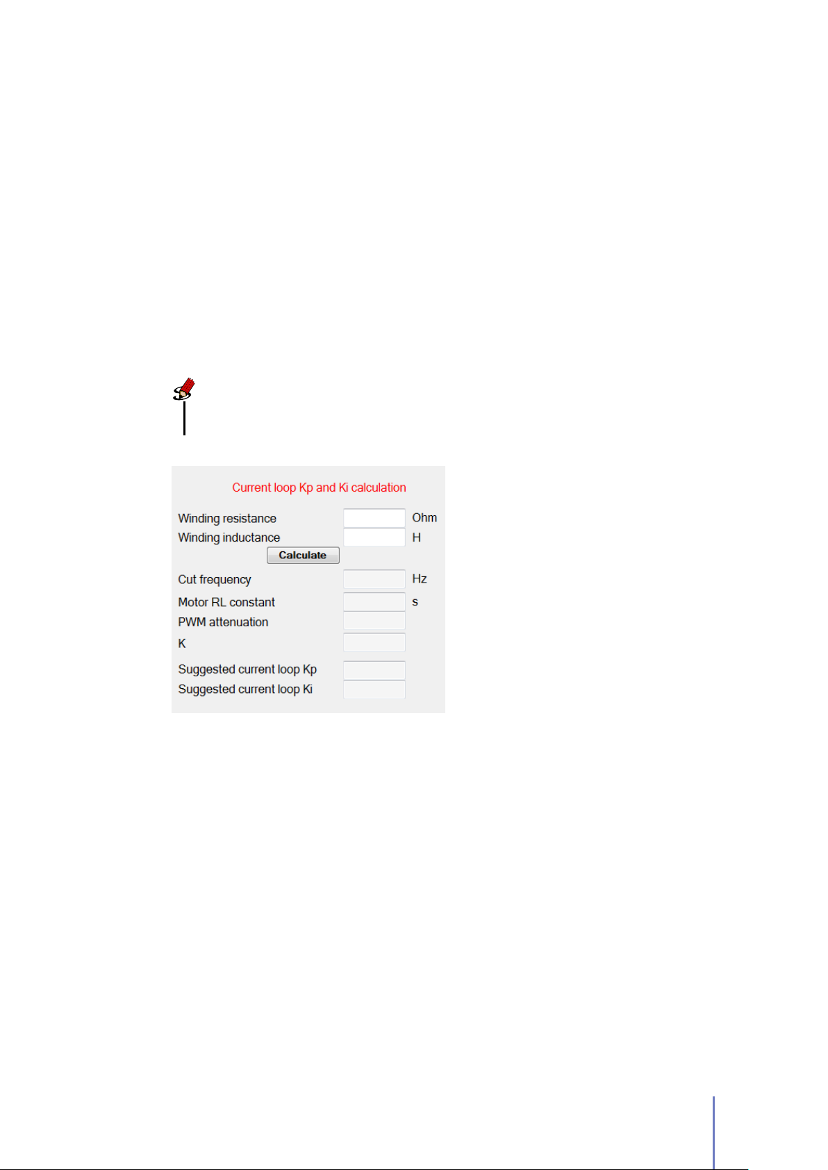
To calculate Kp and Ki values by Telemetry Panel:
1. Move to Autotuning tab (Figure 3.6).
2. Insert the Winding resistance and Winding Inductance value.
3. Click on Calculate button.
Telemetry Panel shows you the value of Kp and Ki and gets you some information
(Cut Frequency, Motor RL Constant, PWM attenuation) which can be useful to tune
Kp and Ki parameters.
Note
Telemetry Panel will automatically send the suggested current loop Kp and Ki
values to UNIDRIVE.
3.5.2 Offset Resolver/SinCos
Finding the correct value of Offset Resolver/SinCos is critical to the proper functioning
of the system. Telemetry Panel helps you determine the correct value of Offset
Resolver/SinCos to sum to resolver/SinCos position:
1. Move to Programmable Parameters tab.
2. Choose RS232 Speed as Configuration.
3.
Move to Autotuning tab and check if
A.
Figure 3.6:
you to estimate gain parameters for
closed-loop current control.
Feedback state
In Autotuning tab allows
is green, else see Appendix
3.5 Auto-tuning UNIDRIVE Parameters 51
Page 56
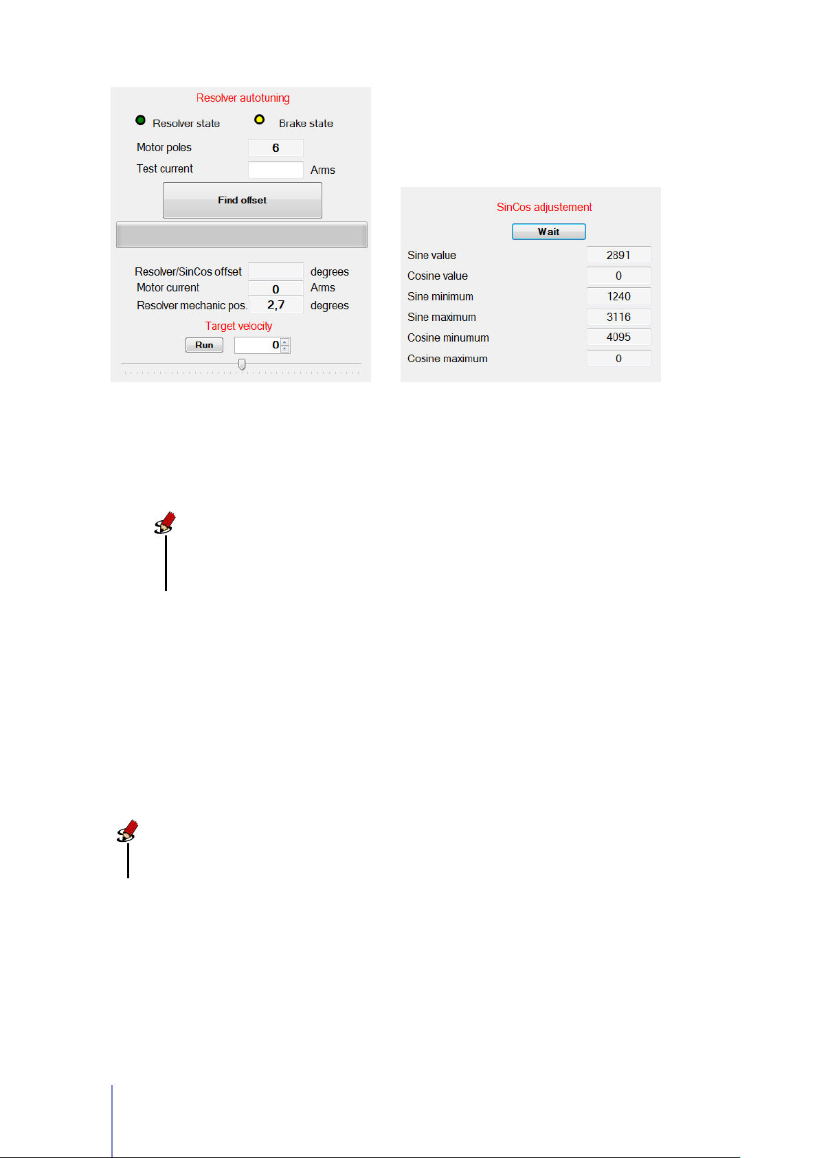
(a) (b)
Figure 3.7:
value
running the SinCos adjustment function (b)
Telemetry Panel helps you to find the correct value of offset Resolver/SinCos
(a)
. In case you’ve mounted a SinCos Encoder on your motor, you must before
Note
For SinCos Encoder:
run the SinCos adjustment function (Figure 3.7b). Click on
and wait for about 30 seconds.
4.
Set the Test Current in
motor dimension and characteristics.
5.
Click on Find Offset button and wait for the progress bar to get completely
green.
Before finding the correct offset value, you must
Start
Amperes RMS
(Figure 3.7a). This value depends on
6. Check that motor runs through Velocity Target trackbar.
button
Note
Telemetry Panel will automatically send the new value of Offset
Resolver/SinCos calculated to UNIDRIVE.
In Resolver Autotuning panel you can see two LED indicators:
Resolver state
resolver is broken. If led is red, it won’t be possible to accomplish resolver
autotuning.
52 Chapter 3 Configuration
This alarm indicates that resolver cable isn’t connected or that
Page 57

Brake state
when unlocked led is yellow. When led is red, it indicates a brake failure.
3.6 EV Mode
The
EV mode
(EV). This operating mode employs sophisticated proprietary algorithms to offer
you a driving experience as much as possible similar to traditional gasoline engine
vehicles. In
and see telemetry data for this operating mode (Figure 3.8).
Warning
A few programmable parameters have no effect in this operating mode: the
gain parameters for closed-loop velocity control, Up Slope and Down slope motor
parameters, the throttle Deadband and Reverse inversion parameter.
In this operating mode you can
unlocking them:
Car EV mode
This led reflects the brake setting: when brake is locked led is green,
is specially designed to control motors mounted in Electric Vehicles
tab you can configure specific programmable parameters
change
the EV programmable parameters after
1. Click on Change Locked Parameters button.
2. Insert the password: 8192
After unlocking, you will be able to change:
Rated braking current
This parameter allows you to limit the maximum current
generated by the motor during braking. The value must meet the battery-specific
requirements.
UN IT MIN VALUE MAX VALUE
Amperes RMS 0 Max
3
Tips and Advice
Lower values of Rated braking current indicate a longer deceleration
time and a more gradual arrest, while bigger values indicate a faster
deceleration.
3
The maximum peak output current depends on the UNIDRIVE model installed.
3.6 EV Mode 53
Page 58
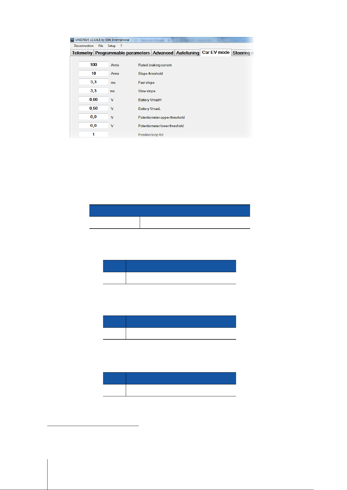
Figure 3.8:
see telemetry data for this operating mode.
In Car EV mode tab you can configure specific programmable parameters and
Slope threshold
At above this value of phase current, UNIDRIVE uses the Fast slope
to give a more responsive feel, below this value the drive uses the Slow slope
in order to provide a smoother ride to increase the driver’s comfort.
UN IT MIN VALUE MAX VALUE
3
Fast slope
mode.
Amperes RMS 0 Max
This option sets the period of time of the Fast slope in this operating
UN IT MIN VALUE MA X VALUE
ms 0 1000
Slow slope
This option sets the period of time of the Slow slope in this operating
mode.
UN IT MIN VALUE MA X VALUE
ms 0 1000
Battery VmaxH
If the battery voltage is above this value, UNIDRIVE gets the
maximum performance as possible.
UN IT MIN VALUE MA X VALUE
V olt 0 Max
4
The maximum battery voltage depends on the UNIDRIVE model installed.
54 Chapter 3 Configuration
4
Page 59
Battery VmaxL
If the battery voltage is below this value, UNIDRIVE decreases the
power output by 1 KW each 10s. This function is designed to slow down and
stop the vehicle in safety conditions.
UN IT MIN VALUE MA X VALUE
V olt 0 Max
4
Potentiometer upper threshold
This value sets the upper threshold of potentiometer.
UN IT MIN VALUE MAX VALU E
V olt 0 5 or 10 *
* In according to the Analogic input option, see Pag. 43.
Potentiometer lower threshold
This value sets the lower threshold of potentiometer.
UN IT MIN VALUE MAX VALU E
V olt 0 5 or 10 *
* In according to the Analogic input option, see Pag. 43.
Position loop Kd
than 16384.
Rotation limiter Kp
Rotation limiter system is designed in order to reduce the jerk motion; it must
be less than 10.
Derivate gain for closed-loop position control; it must be less
Proportional gain for closed-loop rotation limiter control. The
Rotation limiter Ki
Integrate gain for closed-loop rotation limiter control. The
Rotation limiter system is designed in order to reduce the jerk motion; it must
be less than 255.
Maximum power It sets the maximum power available from the UNIDRIVE.
UN IT MIN VALUE MA X VALUE
KW 0 Max
Maximum braking power
It sets the maximum power generated by the motor
during braking. The value must meet the battery-specific requirements.
5
UN IT MIN VALUE MA X VALUE
KW 0 Max
5
The maximum power depends on the UNIDRIVE model installed.
5
3.6 EV Mode 55
Page 60

Lever inversion
15) inputs are inverted.
Direction inversion It allows you to invert the stated direction.
When turned ON, the BACKWARD (PIN 14) and FORWARD (PIN
Reduction ratio
the Reduction ratio. The value is expressed in rational numbers.
Wheel circumference In this textbox you should put the wheel circumference for
correct calculation of the velocity speed (Car speed). The value is expressed in
metres.
In case you use a reduction gear, in this text-box you should insert
Note
The backward maximum speed for this operating mode can be set in
Programmable parameters Tab. See Section 3.4.2.
In Car EV mode tab you can also
operating mode:
Tourque demand
demand.
Motor current This shows the actual motor current (Ampere RM S).
It displays the phase current in order to satisfy the torque
read
the following telemetry data for this
Potentiometer It shows the input voltage read from potentiometer.
Flag Service Debug Information.
Motor velocity
(rpm).
Car speed This textbox shows the estimated actual velocity of the vehicle.
In this tab you can also
Button.
It shows the detected speed, expressed in rotations per minute
plot
the telemetry data reported above, clicking on
Note
The programmable parameters are set in this operating mode have no effect in
other operating modes.
Start
56 Chapter 3 Configuration
Page 61

Monitoring UNIDRIVE
After wiring up correctly UNIDRIVE (See Chapter 2) and adjusting the programmable
parameters (See Chapter 3), you are finally ready to test your system.
Warning
Before starting the test, you had better lift your vehicle up. The driving wheels
must be off the ground and free to rotate. All testing and adjustment must be
done in safe condition.
4.1 LED Diagnostics
UNIDRIVE has an LED light on the front of the device that visually explains what the
driver is doing. Below is the explanation of the different LED’s status:
4
Blinking ORANGE UNIDRIVE works correctly, motor is stopped
Blinking GREEN UNIDRIVE works correctly, motor is running
Steady RED
motor rotation (disabling power relay and three-phase bridge) and unlocks
motor brake.
If
CANopen®mode is set, and the CANopen®FSA State is Switch on disabled,
led will be
independently from alarms or motor state.
UNIDRIVE detects one or more alarms. In this case, UNIDRIVE stops
steady ORANGE
until it will receive shutdown command from PLC,
4.2 Reading Telemetry Data from Telemetry Panel
UNIDRIVE collects several types of telemetry data which allows you to understand
better how your driver works.
Telemetry Panel1shows telemetry data values for each operating mode selected
(Standalone,PLC,EV,CAN Network,RS232).
1
In Chapter 3 is explained the details how install and connect your UNIDRIVE to PC.
57
Page 62
Tips and Advice
In order to test your device for the first time, we suggest to select
Speed or Torque mode) as Configuration in Programmable Parameters tab. So
you will be able to manually set the target velocity of your motor (See Section
2.3.5 and Section 4.2.4).
In Telemetry Panel you can read the following telemetry-data:
Motor velocity It is the detected speed, expressed in rotations per minute (rpm).
Velocity setpoint It displays the actual velocity target. This value is gotten from:
•
The Potentiometer for PLC and Standalone configuration.
•
The
CAN master
as Configuration.
•
The Target Velocity Trackbar for RS232 configuration.
if you set CAN Network or PLC in CANopen®configuration
RS232
(in
Mechanic. pos.
degrees. This is displayed only for Brushless motor with Resolver/SinCos.
Motor current or Torque
the Torque (N ·m) value.
It shows the resolver/encoder mechanical position in mechanical
This shows the actual motor current (
Ampere RMS
Note
You can choose to read either the motor current or the torque in Advanced
tab. See Section 3.4.6.
Heat sink temperature Temperature of UNIDRIVE heat-sink.
Drive Temperature Temperature of UNIDRIVE.
Motor Temperature
parameter in Advanced tab is KTY83/122 or KTY84/130.
This information is available only if Temperature probe type
Note
Under Setup
temperature values in Celsius or Fahrenheit degrees.
*
Temperature Scale menu you can choose to display
) or
Bus voltage It shows the real-time bus voltage.
58 Chapter 4 Monitoring UNIDRIVE
Page 63
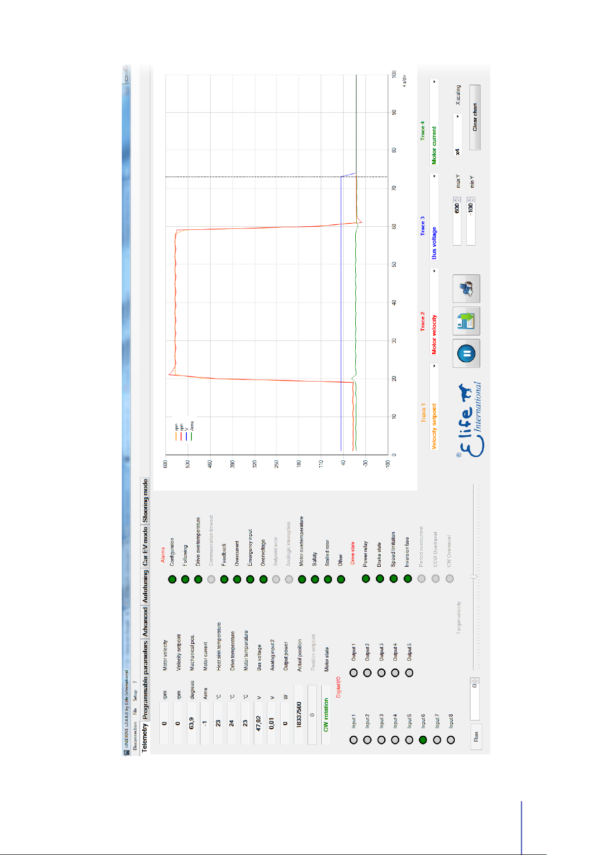
Figure 4.1:
Telemetry Panel displays a wide range of telemetry data and enables you to plot
or log these data over time.
4.2 Reading Telemetry Data from Telemetry Panel 59
Page 64

Analog input 2
(PIN 20).
Output Power It shows the relative electrical output power.
This textbox displays the input voltage of AIN / WIPER POT 2 input
Actual position
is processed only for CAN Network configuration when the operational mode is
Interpolated position mode.
Position setpoint
parameter is processed only for CAN Network configuration when the operational
mode is Interpolated position mode.
Motor state
which direction.
It shows the actual of position control closed-loop. This parameter
It is the position target of position control closed-loop. This
This text box indicates if motor is stopped or if it is running, and in
VALUE DESCRI PTION
CCW rotation Cunterclockwise rotation, backward direction
CW rotation Clockwise rotation, forward direction
4.2.1 Alarm Indicators
The Alarm Indicators on Telemetry tab enable you to determine what kind of errors
are present. When UNIDRIVE detects one or more alarms stops motor rotation
(disabling power relay and three-phase bridge) and unlocks motor brake.
A
green led
means that the alarm is active.
means that the corresponding alarm isn’t signaled, while a
red led
The Alarm indicators are as follows:
Configuration This error appears when:
•
No configuration (Standalone, CAN Network, PLC, EV, RS232) is selected.
•
Set pole number is different from allowed values.
•
The internal memory of UNIDRIVE has never been programmed.
Following
Drive overtemperature
60 Chapter 4 Monitoring UNIDRIVE
This kind of alarm happens when the detected speed is less than
more than 120% over the set time period (See Section 3.4.6).
This alarm happens when the drive temperature is higher
than max drive temperature degrees (See Section 3.4.6).
80%
or
Page 65

Communication timeout
driver measure a communication timeout.
This alarm happens when configuration is
Steering
and
Feedback
Overcurrent
Emergency input
Overvoltage
Setpoint error
Analogic interruption
This alarm indicates that the feedback cable isn’t properly connected or
that the feedback is broken.
It happens whenever one of the modules of three current phases is
higher than a threshold.
It indicates that the emergency input is not supplied, if LED is
yellow it means that drive just set target velocity to0. it is processed only for
PLC, EV, Standalone and for RS232 configuration.
This error is showed when bus voltage is higher than
models and 122 V for 48 ÷ 96 models.
It indicates that speed potentiometer isn’t initially put to0. It’s
processed only for Standalone configuration.
It indicates that analog input for velocity reference isn’t
connected. It’s processed only for PLC and Standalone configuration.
80 V
for
24 ÷ 48
Motor overtemperature This alarm appears when:
•
Motor temperature exceeds Maximum motor temperature value if set PTC
type is KTY83/122 or KTY84/130.
•
Motor temperature sensor isn’t connected if Thermostat is selected as PTC
type.
Safety This alarm is active when the SAFETY Input (PIN 12) isn’t supplied.
Stalled Rotor
the phase current is high about for approximately for a second.
Other This alarm is showed when bus voltage is lower than 12 V.
For information on troubleshooting possible issues, see Appendix A.
It’s alarm appears when the motor is blocked and at the same time
4.2.2 Reset all Current Alarms
In Advanced Tab is present a
alarms.
Reset Alarms
4.2 Reading Telemetry Data from Telemetry Panel 61
button that allows you to reset all running
Page 66
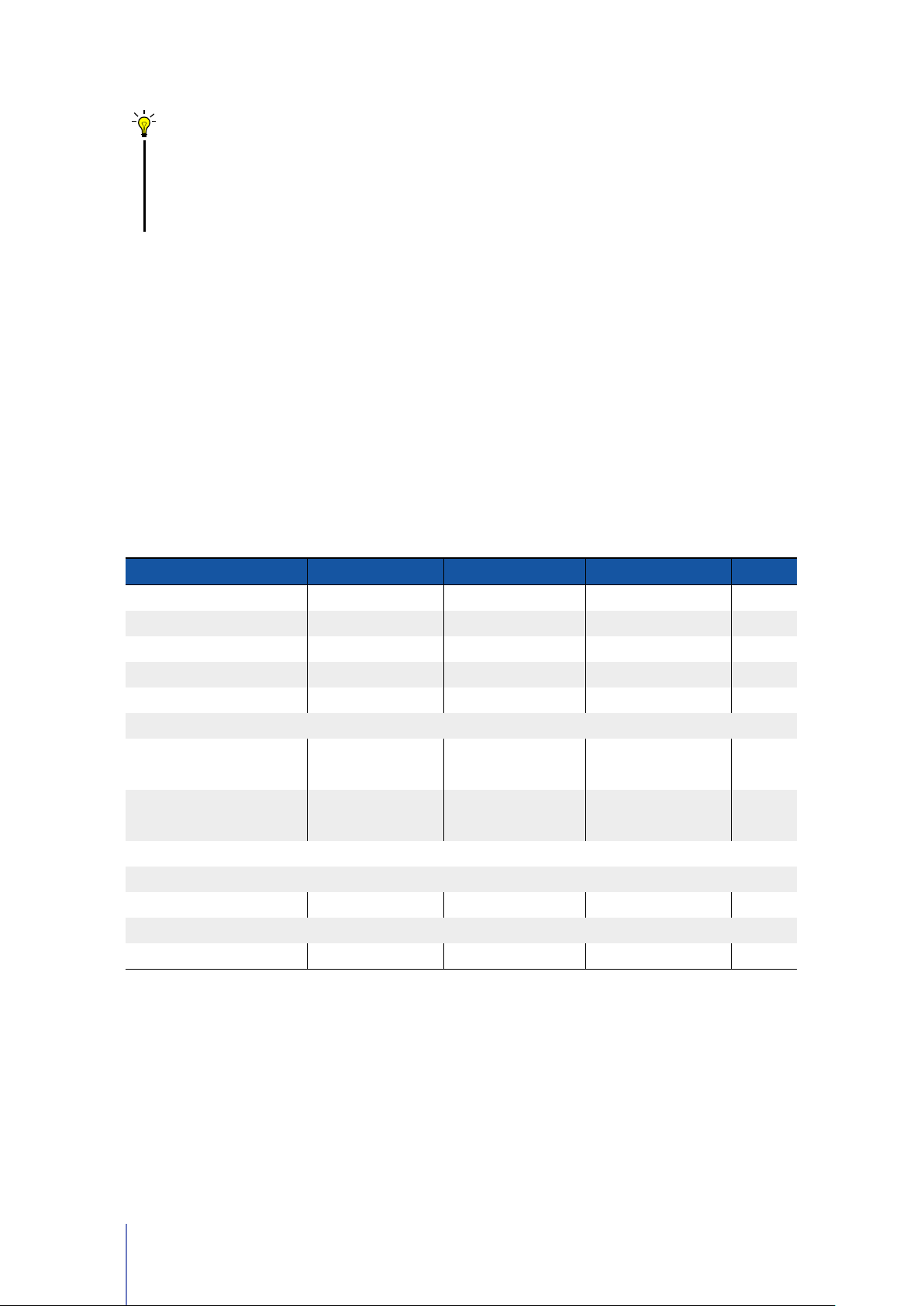
Tips and Advice
It’s also possible to reset all running alarms with a rising edge signal (transition
from low to high) at the
PI N 28
(RESET ALARM) in
configuration and with a fault reset command if you employ
protocol.
4.2.3 Digital I/O and Drive State Indicators
The I/O indicators enables you to read in real-time the status of input and output
signal. If a led indicator is
active: it’s supplied if it’s an input pin or it sends a signal if it’s an output pin.
The meaning of different input/ouput pins in according to the operating mode
selected - PLC,Standalone,EV,CAN Network,RS322 - is given in Table 4.1.
Table 4.1: Description of Digital I/O indicators in Telemetry Panel.
green
means that the corresponding input/output is
Standalone,EV
CAN telemetry
and
PLC
ST
DALONE
AN
Input
Input
Input
Input
Input
Input
Input
Input8ALARM
Output
Output
Output
Output
Output
a
Only if "Analog input" is 0-10V or 0-5V.
BACK
1
FOR
2
3FAST /
HANDBRAKE CCW
4
5
6
7
1
2
Drive
3
4
REVERSE / BRAKE
5
a
WARD
a
WARD
SLOW
/ / / Home
/
RESET
status
RUN
F
CW
C
ALARM
C
P
LC
/ STOP
a
DIR
SLOW
AST /
TRAVEL
OVER
TRAVEL
OVER
AN address
RESET
AN address
/ / / /
SPOR
EMERGENCY
0
0
A
encoder emulator
B
encoder emulator
BACK
FOR
Drive
E
V
a
WARD
a
WARD
ECONOMY
T /
/ P
/ C
/ C
alarm
LIGHT
C
NE TW OR K
AN
Negative
ositive limit
AN address
AN address
/ /
/ /
limit switch
switch
switch
/ /
R
32
S2
/
/
/
0
0
/
/
The
Drive State Indicators
get you some information about the following UNIDRIVE
state:
Power Relay This led reflects the supply relay:
62 Chapter 4 Monitoring UNIDRIVE
Page 67

STATUS MEA NING
Green The relay is enabled
Yellow The relay is disabled
Red Power supply relay failure
Tips and Advice
If you get this alarm only when you give RUN command, this behavior
is probably due to a Resolver problem (See Appendix A and read the
Feedback Alarm troubleshooting).
Brake State This led reflects the brake setting:
STATUS MEANING
Green The brake is locked
Yellow The brake is unlocked
Red The brake failure
Speed Limitation
and so drive is limiting velocity.
Inversion fuse
inverted at least once.
Period overcurrent It’s displayed only for DC motors.
CW overtravel
OVERTRAVEL input is high.
CCW overtavel
OVERTRAVEL input is high.
This is indicator is yellow when quadrature current is saturating
This is indicator is red when
This indicator is yellow when drive is stopped because driver CW
This indicator is yellow when drive is stopped because driver CCW
F+
and
B-
connections have been
Note
Some of these controls can be disabled in Advanced tab. See Section 3.4.6.
4.2.4 The Target Velocity/Torque Track Bar
The Target velocity/Target torque track bar is enabled on Telemetry Tab when
velocity/tourque mode is chosen as Configuration in Programmable Parameters Tab
(Figure 4.2).
4.2 Reading Telemetry Data from Telemetry Panel 63
RS232
Page 68
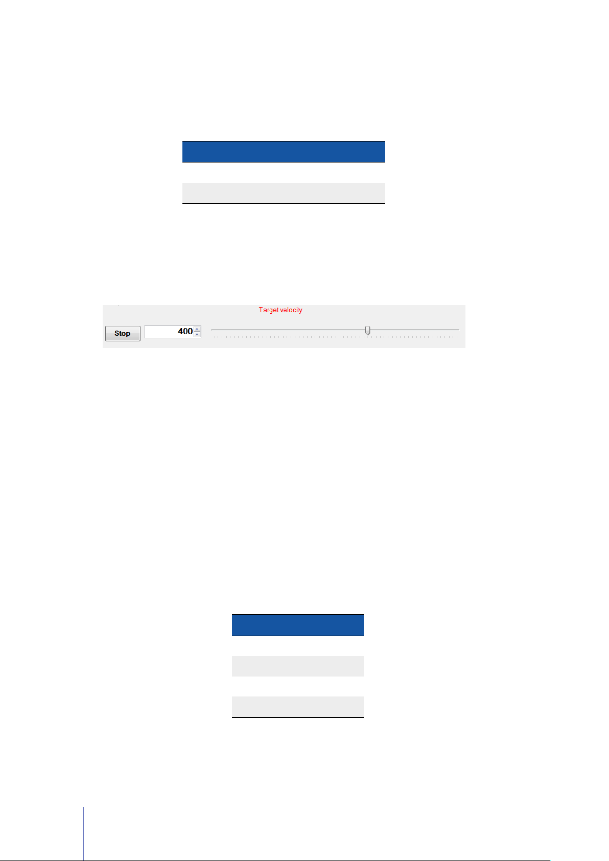
This track bar allows you to manually set the target velocity - or torque - value of
your Motor from 0 to the Max value that you have set as the Max motor Speed (See
Section 3.4.2). The sign of value determine the direction of rotation:
VALUE DIRECTI ON OF ROTATION
Positive CW
Negative CCW
This function can be useful for testing your motor, without worrying about other
devices (e.g: potentiometer) or other controllers (e.g: PLC).
You can also put the exact value of desired target velocity/tourque on the textbox at
the left end of the track bar.
Figure 4.2:
mode has been chosen as Configuration in Programmable Parameters tab.
Target Velocity track bar is enabled by the RS232 mode when this operating
4.3 Plot and Log Telemetry Data in Real-Time
In telemetry Panel you can also plot telemetry data over time and create a log file to
view later in a spreadsheet program.
Telemetry Panel allows you to set the following plot parameters:
Y-axis Scale
the plot.
Time Scaling You can choose how much time to display in X-axis in X Scaling:
Y Max and Y Min set the maximum and minimum value the y-axis of
VALUE DESCRIPTION
x1 1s/div
x2 2s/div
x3 3s/div
. . .
After adjusting the X/Y ranges you can plot and log telemetry data following below
instructions.
64 Chapter 4 Monitoring UNIDRIVE
Page 69
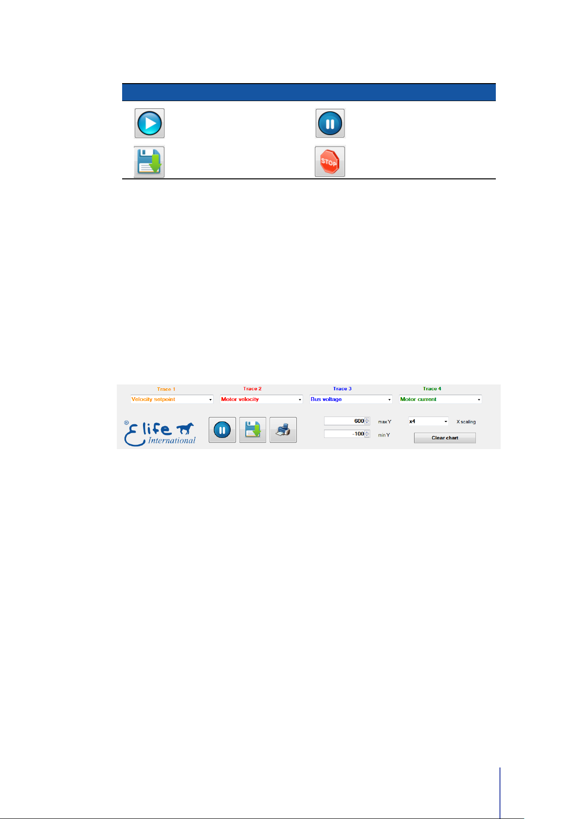
Table 4.2: Plotting and logging telemetry data with Telemetry Panel.
BU TTON FUNCTION BUTTON FUNCTION
Play Button
Start to plot telemetry data
Save Button
Start to log telemetry data
1.
Select one or more (max four) telemetry data that you’ll want to observe from
Stop collecting telemetry data
Pause Button
Stop plotting telemetry data
Stop Button
TRACE 1, TRACE 2,TRACE 3 or TRACE 4 list (Figure 4.3).
2. Click on Play button.
3.
If you want to log these data click on Save button and enter a descriptive name
in the file name box and click Save.
4. Click on Stop button when you want to stop collecting data.
5.
To stop plotting telemetry data and freeze the plot you must click on Pause
button.
Figure 4.3: Telemetry Panel allows you to plot and log one or more telemetry data.
4.3 Plot and Log Telemetry Data in Real-Time 65
Page 70

66
Page 71

Maintenance
UNIDRIVE no needs any maintenance interventions. It’s only necessary to keep the
contacts and the controller clean and dry. The fuse is the only user-serviceable part
in the UNIDRIVE (See Table 2.2, Pag. 11).
Warning
Never attempt to disassemble, repair, or modify the UNIDRIVE yourself, penalty
the voiding of the warranty rules.
If you perform a maintenance operation on your system owing to a problem, it could
be useful to read the
read these messages in one of the following ways:
error messages
that have been sent by UNDRIVE. You can
5
Diagnostic Display
about battery - autonomy and voltage - and UNIDRIVE fault codes.
Telemetry Panel
a wide range of telemetry data (See Chapter 4).
CAN Network
through the CANopen®protocol1.
RS232 You can read the error messages through the RS232 protocol2.
For more information on the meaning of error messages and troubleshooting
procedures, see Section 4.2.1 and Appendix A.
Elife Diagnostic Display allows you to get some information
Telemetry Panel enables you to control your UNIDRIVE and read
The error messages that have been sent by UNIDRIVE can be read
1
For further information, see UNIDRIVE - CANopen®manual
2
For further information, see UNIDRIVE - RS232 Communication Protocol document
67
Page 72

68
Page 73

Troubleshooting: Alarm Messages
This section covers only the common and likely causes of alarm messages and actions
that should be taken by the operator.
UNIDRIVE alarms can be interpreted using the
Elife Diagnostic Display or can be read through the CanOpen®Protocol also.
Note
In Advanced Tab in Telemetry Panel software is present a
that allows you to reset all running alarms.
After the resolution of the problem, UNIDRIVE might need to be restarted.
Telemetry Panel
Reset Alarms
(See Chapter 5),
A
button
Configuration Alarm
DESCRIPTION This error appears when:
•
No configuration (Standalone, CAN Network, PLC, EV, RS232) is selected.
•
Set pole number is different from allowed values.
•
The internal memory of UNIDRIVE has never been programmed.
UNIDRIVE BEHAVIOUR
bridge.
POSSIBLE TROUBLESHOOTING ISSUE
1.
Check if a configuration is selected in the
3.4.1).
2.
If the other programmable parameters are null, it also needs to download
parameters from motor configuration file (See Section 3.3).
After switch on, drive won’t enable power relay and three-phase
Configuration
list (See Section
3. Check if the pole number value is correct (See Section 3.4.5).
69
Page 74

Following Alarm
DESCRIPTION
or more than 120% over the set time period (See Section 3.4.6).
UNIDRIVE BEHAVIOUR
power relay and three-phase bridge) and unlocks motor brake.
POSSIBLE TROUBLESHOOTING ISSUE
the phase current isn’t sufficient to accomplish operation or your motor is
unable to attain the desired speed.
•
•
•
•
This kind of alarm happens when the detected speed is less than
UNIDRIVE stops motor rotation with emergency slope (disabling
There are two possible reasons for this alarm:
Check the integrity of the fuse.
Check if the motor is braked.
Check the maximum phase current (See Section 3.4.5) is correct for your
motor.
Check if the gain parameters for closed-loop velocity control fit your
needs.
80%
•
Increasing the Following error delay value (See Section 3.4.6).
•
Decrease the Max motor speed if your motor is unable to achieve it (See
Section 3.4.2).
Drive overtemperature Alarm
DESCRIPTION
set maximum drive temperature degrees (See Section 3.4.6).
UNIDRIVE BEHAVIOUR
power relay and three-phase bridge) and unlocks motor brake.
POSSIBLE TROUBLESHOOTING ISSUE
reset alarms. If the error appears frequently, you must improve heat exchange
between the UNIDRIVE and the vehicle surface (See Section 2.1).
This alarm happens when the drive temperature is higher than the
UNIDRIVE stops motor rotation with emergency slope (disabling
Restore drive temperature conditions, then
70 Chapter A Troubleshooting: Alarm Messages
Page 75

Communication timeout Alarm
DESCRIPTION
measure a communication timeout.
UNIDRIVE BEHAVIOUR
power relay and three-phase bridge) and unlocks motor brake.
POSSIBLE TROUBLESHOOTING ISSUE
the UNIDRIVE and master (See UNIDRIVE - Steering Mode Manual).
This alarm happens when configuration is
UNIDRIVE stops motor rotation with emergency slope (disabling
Check configuration and wiring between
Steering
Feedback Alarm
DESCRIPTION
appears when your motor is running, the possible causes are:
•
The Feedback cable isn’t properly connected or otherwise if this error
Lack of earth interconnection between motor housing and driver negative
terminal (-).
and master
•
Probable leakage between motor housing and phases.
•
The Feedback cable passed near power cables.
•
For Resolver and SinCos:
stator and rotor (this results in driver input signal undervoltage).
•
For Hall Sensor: The Hall sensors are not precisely linked.
UNIDRIVE BEHAVIOUR
power relay and three-phase bridge) and unlocks motor brake.
POSSIBLE TROUBLESHOOTING ISSUE Firstly
UNIDRIVE stops motor rotation with emergency slope (disabling
Radial misalignment between Resolver/SinCos
, check the feedback cable connection:
1. Check the feedback cable connection on driver/feedback side.
2.
Check the electrical integrity of the cable, pay specific attention to the
cable’s shield.
3.
Ensure that the feedback cable was constructed specifically for the feedback
type mounted on your motor. It’s essential that the feedback cable is of
the high quality.
71
Page 76

If these checks failed, you must:
1.
Check the correct connection between motor housing appropriate terminal
and driver negative terminal (-).
2. Check electrical isolation between every phase and motor housing.
3. Pass feedback cable as far as possible from power cables.
4. Check the correct Resolver/SinCos installation within motor.
Overcurrent Alarm
DESCRIPTION
higher than a threshold.
UNIDRIVE BEHAVIOUR
power relay and three-phase bridge) and unlocks motor brake.
POSSIBLE TROUBLESHOOTING ISSUE The possible actions that should be taken:
•
•
If this error appears when your motor is in
generated by your motor is higher than the battery voltage: Change your
battery system or decrease the Max motor speed value (See Section 3.4.2).
It happens whenever one of the modules of three current phases is
UNIDRIVE stops motor rotation with emergency slope (disabling
Check the proper functioning of the feedback system.
Check if the gain parameters for closed-loop current control are not too
high for your application (See Section 3.4.5).
generator mode
, the voltage
Emergency input Alarm
DESCRIPTION
only for PLC, EV, Standalone and for RS232 configuration.
UNIDRIVE BEHAVIOUR
power relay and three-phase bridge) and unlocks motor brake.
POSSIBLE TROUBLESHOOTING ISSUE
reset alarms.
72 Chapter A Troubleshooting: Alarm Messages
It indicates that the emergency input is not supplied. It’s processed
UNIDRIVE stops motor rotation with emergency slope (disabling
Check the Emergency Input (
PI N 3
), then
Page 77

Overvoltage Alarm
DESCRIPTION
models and 122 V for 48 ÷ 96 models.
UNIDRIVE BEHAVIOUR
power relay and three-phase bridge) and unlocks motor brake.
POSSIBLE TROUBLESHOOTING ISSUE
alarm:
•
•
This error is showed when bus voltage is higher than
UNIDRIVE stops motor rotation with emergency slope (disabling
There are two possible explanation for this
Battery voltage, or battery charging voltage, is too high for the UNIDRIVE
Type installed.
The voltage generated by your motor, when is in
higher than the battery voltage: Change your battery system or decrease
the Max motor speed value (See Section 3.4.2).
Setpoint Alarm
80 V
for
24 ÷ 48
generator mode
, is
DESCRIPTION
speed potentiometer is grater than 25% of the end-of-stroke during the start
phase of the motor. It’s processed only for Standalone configuration.
UNIDRIVE BEHAVIOUR After switch on, drive won’t let motor run.
POSSIBLE TROUBLESHOOTING ISSUE
then reset alarms.
It indicates that the speed potentiometer isn’t initially put to 0 or the
Put the speed potentiometer to idle state,
Analogic interruption Alarm
DESCRIPTION
It is processed only for PLC and Standalone configurations.
UNIDRIVE BEHAVIOUR
or break during run operation, UNIDRIVE stops motor rotation with emergency
slope (disabling power relay and three-phase bridge) and unlocks motor brake.
It indicates that analog input for velocity reference isn’t connected.
When motor is rotating, if analog input cable will disconnect
POSSIBLE TROUBLESHOOTING ISSUE
WIPER POT) and UNIDRIVE.
Check the wiring between
PI N 21
(AIN /
73
Page 78

Motor overtemperature Alarm
DESCRIPTION This alarm appears when:
•
Motor temperature exceeds Maximum motor temperature value if set
Temperature probe type is KTY83/122 or KTY84/130.
•
Motor temperature sensor isn’t connected if Thermostat is selected as
Temperature probe type.
UNIDRIVE BEHAVIOUR
power relay and three-phase bridge) and unlocks motor brake.
POSSIBLE TROUBLESHOOTING ISSUE
probe type option (See Section 3.4.6. Otherwise, restore motor temperature
conditions, then reset alarms.
UNIDRIVE stops motor rotation with emergency slope (disabling
If motor hasn’t any PTC, set
none
Safety Alarm
DESCRIPTION
UNIDRIVE BEHAVIOUR
power relay and three-phase bridge) and unlocks motor brake.
POSSIBLE TROUBLESHOOTING ISSUE
restart your UNIDRIVE.
This alarm is active when the SAFETY Input (PIN 12) isn’t supplied.
UNIDRIVE stops motor rotation with emergency slope (disabling
Check the connection of SAFETY input and
as Temperature
Stalled rotor Alarm
DESCRIPTION
the phase current is high about for approximately for a second. For instance,
the vehicle’s wheels are blocked by an obstacle.
UNIDRIVE BEHAVIOUR Drive won’t enable power relay and three-phase bridge.
POSSIBLE TROUBLESHOOTING ISSUE
it.
74 Chapter A Troubleshooting: Alarm Messages
This alarm appears when the motor is blocked and at the same time
Find the cause of the block and then remove
Page 79

Other
DESCRIPTION This alarm is showed when bus voltage is lower than 12 V.
UNIDRIVE BEHAVIOUR
bridge.
POSSIBLE TROUBLESHOOTING ISSUE The possible actions that should be taken:
•
Check the integrity of the fuse.
•
If this error appears always when you run UNIDRIVE, contact the technical
assistance.
After switch on, drive won’t enable power relay and three-phase
75
Page 80

76
Page 81
Index of Programmable
Parameters
Table B.1: Index of UNIDRIVE Programmable Parameters in alphabetical order.
B
NA ME
OP ERATI NG RANGE
UN IT MIN MAX by CANOPE N
Analogic input
Analog output
Analog output
function
Backward maximum
speed
Brake current
reduction
Brake fault alarm
CANopen®address integer 0 127 Pag. 43
CANopen®baudrate
Configuration
Current Loop Ki a.u. 0 512 • Pag. 44
allowed values
allowed values
allowed values
rpm 0 7000 Pag. 42
% 0 50 Pag. 45
boolean value
allowed values
allowed values
PR OG RA MM AB LE
®
RE FERENCE
Pag. 43
Pag. 48
Pag. 48
Pag. 48
Pag. 43
Pag. 41
Current Loop Kp a.u. 0 1024 • Pag. 44
Deadband % 0 50 Pag. 43
Down slope rpm/s 500 35 • 10
Emergency input fault
Emergency Slope rpm/s 500 35 • 10
Following error delay s 0 15 • Pag. 41
Hall sensor phashing degree 60 120 Pag. 46
Lower battery dinamic
decrease
boolean value
boolean value
5
5
• Pag. 42
• Pag. 49
Continued on next page . . .
Pag. 49
Pag. 48
77
Page 82
. . . continued from previous page
NA ME
OP ERATI NG RANGE
UN IT MIN MAX by CANOPE N
Max drive temperature
(°F)
Max motor speed rpm 0 7000 • Pag. 42
°C
Max speed at slow
mode
Maximum motor
temperature
Maximum phase
current
Motor poles integer 4 44 Pag. 44
NH Alarm Output
Overtravel warning
Phase Advance a.u. 0 32 Pag. 44
rpm 0 7000 Pag. 42
°C
(°F)
Amperes
RMS
80
(176)
0
(32)
110
(230)
255
(491)
0 Max • Pag. 45
boolean value
boolean value
PR OG RA MM AB LE
®
RE FERENCE
Pag. 41
Pag. 49
Pag. 41
Pag. 48
Phase
offset(backward)
Phase zero degree 0 359.99 Pag. 46
Position Loop Ki a.u. 0 128 • Pag. 40
Position Loop Kp a.u. 0 16384 • Pag. 40
Potentiometer Supply
Reference inversion
Resolver/SinCos offset degree 0 359.99 • Pag. 46
RPD02 transmission
type
Size Indicator
Supply fault alarm
Temperature probe
type
Torque constant N·m/A 0 10 • Pag. 48
degree 0 359.99 Pag. 46
allowed values
boolean value
Pag. 49
Pag. 43
integer 1 255 • Pag. 50
boolean value
boolean value
allowed values
Pag. 43
Pag. 48
Pag. 49
TPD02 transmission
type
integer 1 255 • Pag. 50
78 Chapter B Index of Programmable Parameters
Continued on next page . . .
Page 83

. . . continued from previous page
NA ME
OP ERATI NG RANGE
UN IT MIN MAX by CANOPE N
Up slope rpm/s 500 35 • 10
Velocity Loop Ki a.u. 0 1024 • Pag. 40
Velocity Loop Kp a.u. 0 4096 • Pag. 40
PR OG RA MM AB LE
5
RE FERENCE
®
• Pag. 42
Concluded
79
Page 84

© Elife International 2016
www.elifeinternational.com
 Loading...