

Page 1

SmartWave™
Switching
Amplifier
Operation Manual
This manual covers models:
SW5250A
SW3500A
SW1750A
ELGAR ELECTRONICS CORPORATION
9250 Brown Deer Road
San Diego, CA 92121-2294
1-800-733-5427
Tel: (858) 450-0085
Fax: (858) 458-0267
Email: [email protected]
www.elgar.com
©2002 by Elgar Electronics Corporation
This document contains information proprietary to Elgar Electronics Corporation. The information contained herein is
not to be duplicated or transferred in any manner without prior written permission from Elgar Electronics Corporation.
July 19, 2002 Document No. M162001-01 Rev F
Page 2

.
Page 3

ELGAR ONE–YEAR WARRANTY
Elgar Electronics Corporation (hereinafter referred to as Elgar) warrants its products to be free from defects
in material and workmanship. This product warranty is effective for one year from the date of shipment to
the original purchaser. Liability of Elgar under this warranty shall exist provided that:
• the Buyer exposes the product to normal use and service and provides normal maintenance on the
product;
• Elgar is promptly notified of defects by the Buyer and that notification occurs within the warranty period;
• the Buyer receives a Return Material Authorization (RMA) number from Elgar’s Customer
Service Department prior to the return of the product to Elgar for repair, phone 800-73-ELGAR
(800-733-5427), ext. 2295;
• the Buyer returns the defective product in the original, or equivalent, shipping container;
• if, upon examination of such product by Elgar it is disclosed that, in fact, a defect in materials and/or
workmanship does exist, that the defect in the product was not caused by improper conditions, misuse, or
negligence; and,
• that Elgar markings and nameplates have not been altered or removed and the equipment has not been
repaired or modified by anyone other than Elgar authorized personnel.
This warranty is exclusive and in lieu of all other warranties, expressed or implied, including, but not limited
to, implied warranties of merchantability and fitness of the product to a particular purpose. Elgar, its agents,
or representatives, shall in no circumstance be liable for any direct, indirect, special, penal, or consequential
loss or damage of any nature resulting from the malfunction of the product. Remedies under this warranty
are expressly limited to repair or replacement of the product.
CONDITIONS OF WARRANTY
• To return a defective product, contact an Elgar representative or the Elgar factory for an RMA number.
Unauthorized returns will not be accepted and will be returned at the shipper’s expense.
• For Elgar products found to be defective within thirty days of receipt by the original purchaser, Elgar will
absorb all ground freight charges for the repair. Products found defective within the warranty period, but
beyond the initial thirty-day period, should be returned prepaid to Elgar for repair.
• Normal warranty service is performed by Elgar during the weekday hours of 7:30 am to 4:30 pm Pacific
time. Warranty repair work requested to be accomplished outside of normal working hours will be subject
to Elgar non-warranty service rates.
• Warranty field service is available on an emergency basis. Travel expenses (travel time, per diem expense,
and related air fare) are the responsibility of the Buyer. A Buyer purchase order is required by Elgar prior to
scheduling.
• A product found, upon inspection by Elgar, to be in specification is subject to an inspection fee and
applicable freight charges.
• Equipment purchased in the United States carries only a United States warranty for which repair must be
accomplished at the Elgar factory.
i
Page 4

Committed to Quality...Striving for Excellence
ii
Page 5

This page intentionally left blank.
iii
Page 6
SAFETY NOTICE
Before applying power to the system, verify that the SW Series unit is configured properly for the user’s
particular application.
WARNING!
Hazardous voltages in excess of 280 VRMS, 600V peak may be present when
covers are removed. Qualified personnel must use extreme caution when
servicing this equipment. Circuit boards, test points, and output voltages
may be floating above (below) chassis ground.
Installation and service must be performed by qualified personnel who are aware of dealing with attendant
hazards. This includes such simple tasks as fuse verification.
Ensure that the AC power line ground is connected properly to the SW Series unit input connector
or chassis. Similarly, other power ground lines including those to application and maintenance
equipment must
Always ensure that facility AC input power is de-energized prior to connecting or disconnecting the
input/output power cables.
inadvertent contact with hazardous voltages is eliminated. To guard against risk of electrical shock during
open cover checks, do not touch
can retain an electrical charge. Use safety glasses during open cover checks to avoid personal injury by any
sudden failure of a component.
be grounded properly for both personnel and equipment safety.
During normal operation, the operator does not have access to hazardous voltages within the
chassis. However, depending on the user’s application configuration, HIGH VOLTAGES
HAZARDOUS TO HUMAN SAFETY may be generated normally on the output terminals.
Ensure that the output power lines are labeled properly as to the safety hazards and that any
any portion of the electrical circuits. Even when the power is off, capacitors
Due to filtering, the unit has high leakage current to the chassis. Therefore, it is essential to operate this unit
with a safety ground.
Some circuits are live even with the front panel switch turned off. Service, fuse verification, and
connection of wiring to the chassis must be accomplished at least five minutes
removed via external means; all circuits and/or terminals to be touched must be safety grounded to
the chassis.
After the unit has been operating for some time, the metal near the rear of the unit may be hot enough to
cause injury. Let the unit cool before handling.
Qualified service personnel need to be aware that some heat sinks are not at ground, but at high potential.
CAUTION!
after power has been
380V 3-phase input power systems (4–wire) must have a neutral connection.
The neutral must not be switched. Apply neutral before phase voltage or
serious damage to the equipment may result.
iv
Page 7
ying
For safe operation, it is required that output power neutral be connected to chassis ground. The SW system
is shipped with a ground wire between power neutral and chassis ground.
These operating instructions form an integral part of the equipment and must be available to the operating
personnel at all times. All the safety instructions and advice notes are to be followed.
Neither Elgar, San Diego, California, USA, nor any of the subsidiary sales organizations can accept any
responsibility for personal, material or consequential injury, loss or damage that results from improper use of
the equipment and accessories.
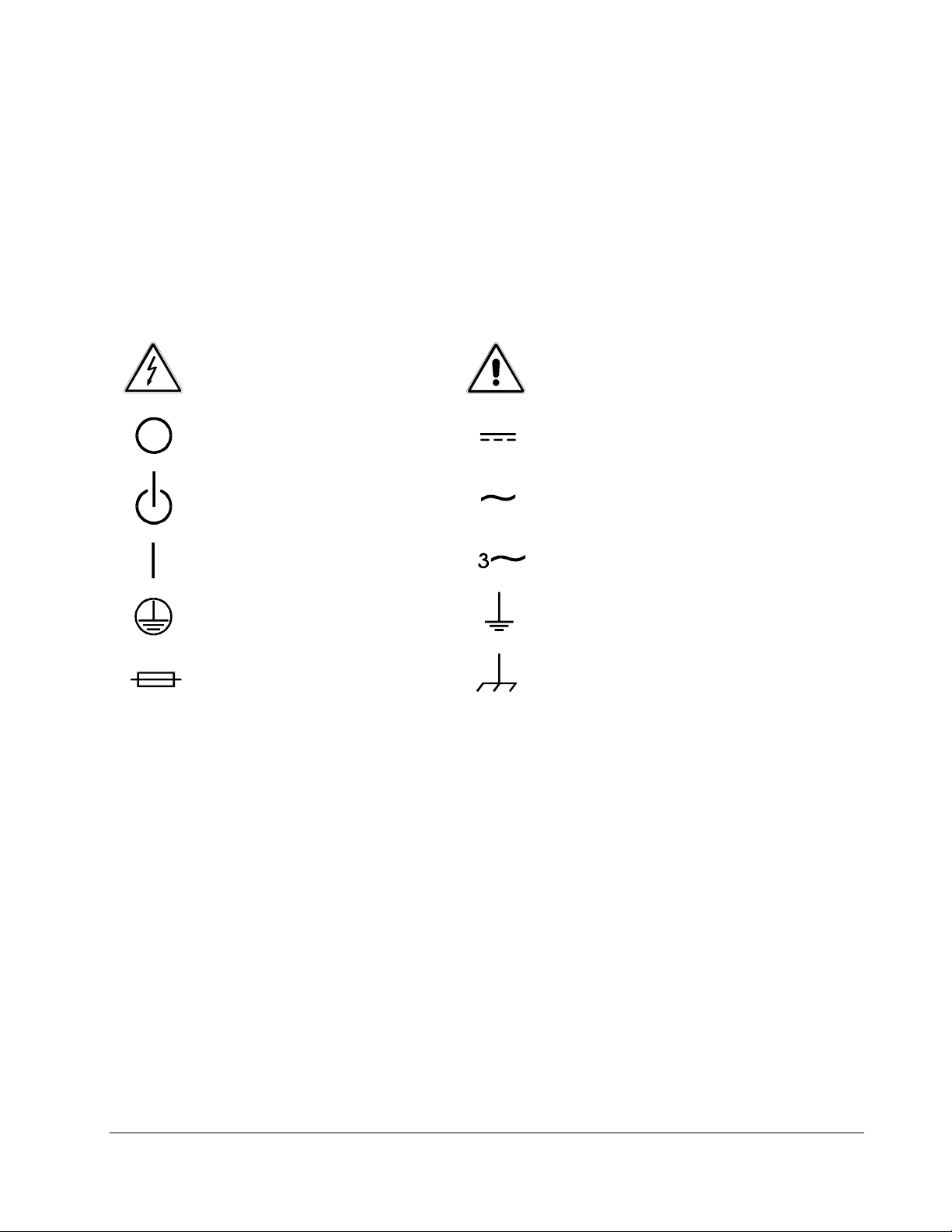
SAFETY SYMBOLS
CAUTION
Risk of El ec trical Shock
Off (Suppl y )
Standby (Supply)
On (Sup pl y )
Protective Conductor Terminal
Fuse
CAUTION
Refer to Accompan
Direct Current (DC)
Alternating
Three–Phase
Earth (G round) Terminal
Chassis Ground
Current (AC)
Alternating Current
Document s
v
Page 8

Page 9

CONTENTS
SECTION 1 GENERAL DESCRIPTION
1.1 Introduction.................................................................................................... 1-1
1.2 Input Specifications ....................................................................................... 1-3
1.3 Output Specifications: Normal Operation Mode............................................. 1-3
1.4 Waveform Specifications...............................................................................1-5
1.5 Measurements (Optional)..............................................................................1-5
1.5.1 Parameters Measured....................................................................... 1-5
1.5.2 Measurement Capabilities and Accuracies ....................................... 1-6
1.6 Protection and Safety .................................................................................... 1-9
1.7 Agency Requirements ................................................................................... 1-9
1.8 Physical Specifications (All Models) ............................................................ 1-10
1.9 Environmental Data..................................................................................... 1-10
1.10 Other Standard Features............................................................................. 1-10
1.11 Options........................................................................................................ 1-12
1.12 Glossary of Technical Terms....................................................................... 1-13
1.12.1 RMS Servo...................................................................................... 1-13
1.12.2 Servo Boost..................................................................................... 1-13
1.12.3 X-Load............................................................................................. 1-14
SECTION 2 INSTALLATION
2.1 Introduction.................................................................................................... 2-1
2.2 Unpacking...................................................................................................... 2-1
Operation Manual v
Page 10

Contents SW 5250A•SW 3500A•SW 1750A
2.3 Pre-installation Inspection..............................................................................2-2
2.4 Installation......................................................................................................2-2
2.5 Air Intake and Exhaust...................................................................................2-2
2.6 Installation/Dimensional Drawing ...................................................................2-3
2.7 Input/Output Connectors................................................................................2-6
2.7.1 BNC Connectors................................................................................2-7
2.7.2 EXT IN (External Input)......................................................................2-7
2.7.3 DFI (Direct Fault Indicator) ................................................................2-8
2.7.4 IEEE 488.2.........................................................................................2-9
2.7.5 Slave Connector................................................................................2-9
2.7.6 Grounding........................................................................................2-10
2.8 Input Power Requirements...........................................................................2-10
2.8.1 187 to 264 VRMS L–L 3-Phase Operation (3-Wire USA) ................2-12
2.8.2 342 to 457 VRMS L–L 3-Phase Operation (4-Wire INTL)................2-12
2.8.3 Single-Phase Input Connections......................................................2-12
2.9 Output Connections to the Load...................................................................2-13
2.9.1 SW 5250A Output Connections.......................................................2-13
2.9.2 SW 3500A and SW 1750A Output Connections..............................2-15
2.9.3 Wiring of Unit...................................................................................2-15
2.10 Wire Gauge Selection ..................................................................................2-15
SECTION 3 OPERATION
3.1 Introduction ....................................................................................................3-1
3.2 Front Panel Controls......................................................................................3-1
3.3 Menus ............................................................................................................3-3
3.3.1 MAIN MENU......................................................................................3-4
3.3.2 PROGRAM Menu..............................................................................3-5
3.3.3 MEASURE Menu...............................................................................3-8
3.3.4 WAVEFORM Menu............................................................................3-9
3.3.5 SEQUENCE Menu...........................................................................3-15
3.3.6 INSTR (Instrument) Menu................................................................3-23
3.3.7 SYSTEM Menu................................................................................3-24
vi Operation Manual
Page 11

SW 5250A•SW 3500A•SW 1750A Contents
3.4 Front Panel Programming Conventions....................................................... 3-33
3.5 Front Panel Programming Exercises........................................................... 3-34
3.5.1 Current Inrush Example .................................................................. 3-34
3.5.2 Voltage Spike Example................................................................... 3-38
3.5.3 Voltage Dropout Example ............................................................... 3-42
3.6 SCPI Specification....................................................................................... 3-45
SECTION 4 STANDARD WAVEFORMS
LIST OF TABLES
Table 2–1 Recommended Mounting Slide.................................................................. 2-3
Table 2–2 SW Input/Output Connectors (see Figure 2–3).......................................... 2-6
Table 2–3 EXT IN Connector Pinout........................................................................... 2-7
Table 2–4 DFI Connector Pinout................................................................................. 2-8
Table 2–5 IEEE 488.2 Connector Pinout .................................................................... 2-9
Table 2–6 Slave Connector Pinout ............................................................................. 2-9
Table 2–7 Input Currents for 3-Phase Input Power................................................... 2-11
Table 2–8 Single-Phase Input Configurations........................................................... 2-11
Table 2–9 Recommended Wire Gauge Selection Guide........................................... 2-16
Table 3–1 Sequence Execute Menu.......................................................................... 3-22
Table 3–2 SELF-TEST Results Definitions............................................................... 3-25
Table 3–3 System External Menu............................................................................. 3-28
Table 3–4 Fault Register Bit Definitions.................................................................... 3-29
Table 3–5 Fault Description and Action (FR1).......................................................... 3-30
Table 3–6 Fault Description and Action (FR2).......................................................... 3-31
Table 3–7 Fault Description and Action (FR3).......................................................... 3-31
Operation Manual vii
Page 12

Contents SW 5250A•SW 3500A•SW 1750A
LIST OF FIGURES
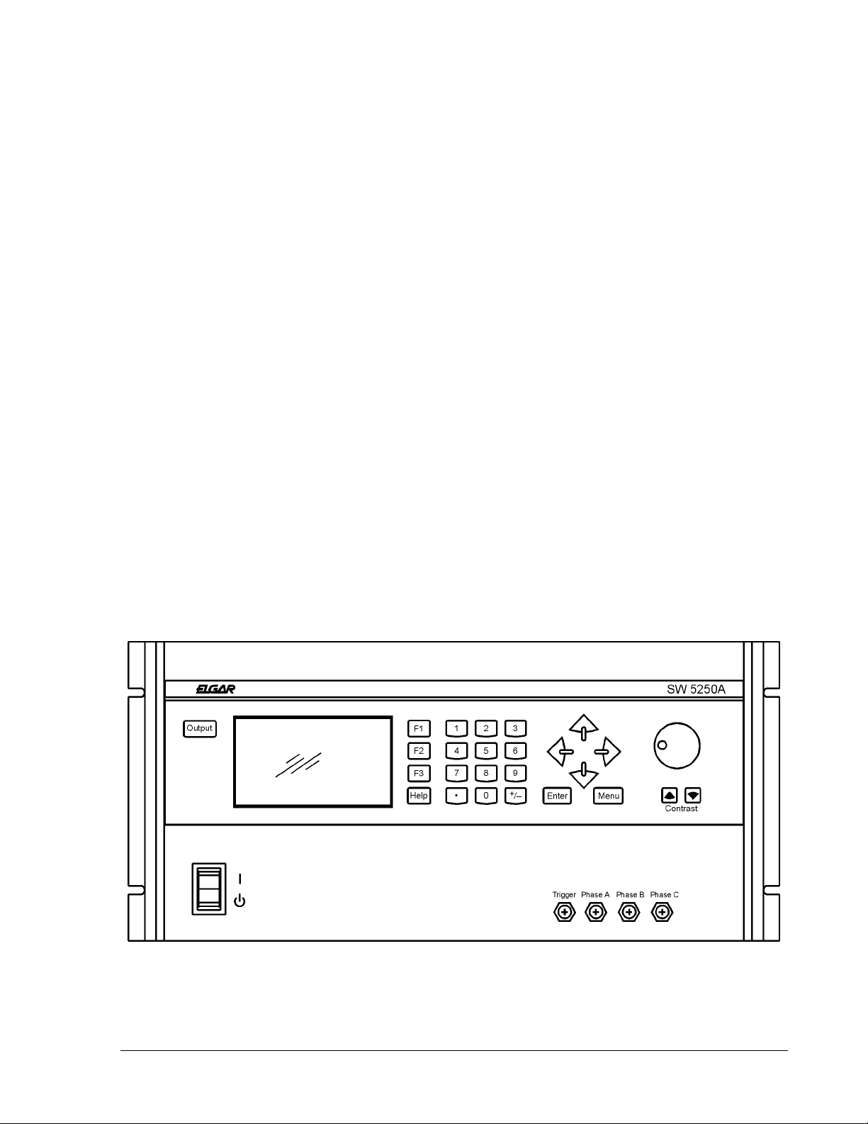
Figure 1–1 Elgar Model SW 5250A AC Power Source (Rack Mount Version) ...........1-1
Figure 2–1 Mounting Dimensions, SmartWave Front View .........................................2-3
Figure 2–2 Mounting Dimensions, SmartWave Top and Side Views...........................2-4
Figure 2–3 SmartWave Rear Panel.............................................................................2-5
Figure 2–4 Parallel Connections................................................................................2-14
Figure 2–5 Sense Lead Connections for 3-Phase Output .........................................2-14
Figure 3–1 Front Panel Controls (SW 5250A).............................................................3-1
viii Operation Manual
Page 13
SECTION 1
GENERAL DESCRIPTION
1.1
The Elgar SmartWaveTM Models SW 5250A, SW 3500A, and SW 1750A use transformerless, direct coupled amplifiers and a true arbitrary waveform generator based
controller. This technology allows you to create, edit and generate complex waveforms
with high DC content for critical ATE and power line disturbance simulation testing.
The SmartWave can create complex waveforms with high DC content for simulating real
world power irregularities, including phase controlled sub-cycle or multi-cycle dropouts,
spikes, sags, surges, frequency excursions, plus frequency and voltage ramps
(sweeps). The unit can also generate clipped waveforms, harmonic distortion, high
current inrush, and other complex waveshapes.
Introduction
Figure 1–1 Elgar Model SW 5250A AC Power Source (Rack Mount Version)
Operation Manual 1-1
Page 14
General Description SW 5250A•SW 3500A•SW 1750A
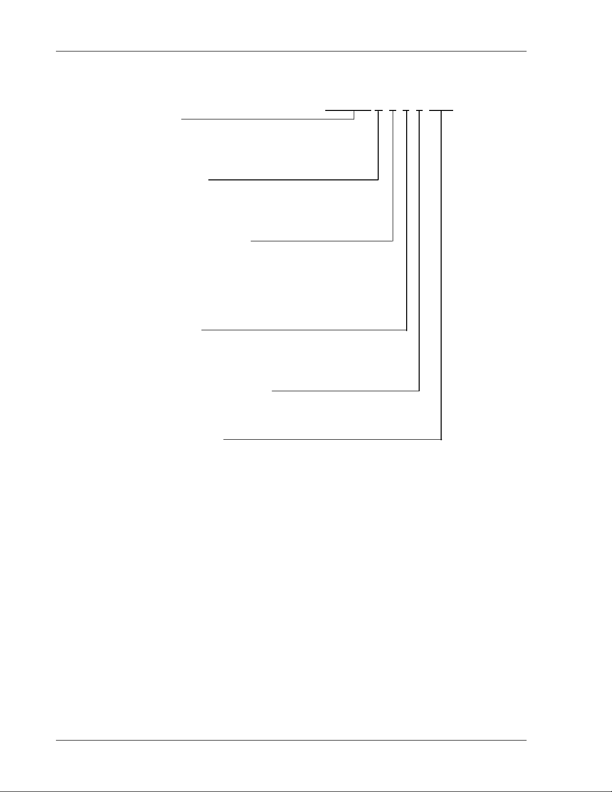
The SmartWave model numbers are identified below:
Power Options:
5250
3500
1750
Chassis Description:
A = Standard High Impedance
AE = Standard IEC Low Impedance
M, ME, S, SE = N/A
Power Conditioning Options:
1 = Rectifier USA
2 = Rectifier International
3 = PFC USA
4 = PFC International
5, 6 = N/A
Controller Options:
1 = Manual
2 = GPIB
3 = Arbitrary GPIB
Test and Measurement Options:
1 = No T&M
2 = Standard T&M
SW5250
A–1–3–2–XXX
Non-Standard Options:
Blank = None
Programming is accomplished at the front panel or with a personal computer (PC) using
optional software. A GPIB card in the computer is also required.
A library of 50 factory-supplied waveshapes is provided in Flash Memory. Non-volatile
memory storage is available for an additional 50 user-created waveshapes.
Waveshapes from the libraries can be assigned amplitude and frequency parameters
and be stored as setups in non-volatile memory for immediate user recall. In addition,
you can create up to 1000 timed segments and link them together to form sequences
(transient programs).
The backlit graphics LCD display allows quick confirmation of waveforms when created
or edited from the front panel. Front panel BNCs provide waveform reference outputs
for oscilloscope viewing. The front panel also includes a keypad, a rotary knob, and
Help screens.
1-2 Operation Manual
Page 15

SW 5250A•SW 3500A•SW 1750A General Description
The SmartWave sources are true DC as well as AC power supplies. Up to 312 VRMS
are available in AC or AC+DC modes. Multi-phase models can be switched to single or
three-phased operation via the front panel or the GPIB.
A wide frequency range of DC or 40 Hz to 5 kHz is available for a broad array of
applications. Utilizing the latest in AC switch mode technology, the SmartWave has
less than -60 dB of noise and ripple with total harmonic distortion (THD) of <0.5% to 500
Hz. A crest factor of 4.0 provides high peak-to-RMS current capability. An optional
power factor correction (PFC) of .99 is also available.
1.2
Input Power Ranges: Factory configured 187 to 264 VRMS, 3φ L-L (3 wire),
or 342 to 457 VRMS, 3φ L-L (4 wire). A chassis ground is also required for safety.
Input Power Factor: .6 with USA rectifier; .35 with INTL rectifier;
.99 with input PFC option.
Input Frequency Range: 47 to 63 Hz (47 to 440 Hz for PFC input only)
Efficiency: 70%, minimum, at full load.
Ride Through: 3 msec, minimum; 10 msec, minimum, with PFC option.
Input Current: Maximum currents are provided in Table 2–7 and Table 2–8.
Initial Turn-on Current Surge: Limited to less than peak value listed in
Table 2–7 and Table 2–8.
1.3
Calibration Interval: 1 year.
Input Specifications
Output Specifications: Normal Operation Mode
Power Factor of Load: 0 lagging to 0 leading.
AC or DC Output Voltage: 0 to 156 VRMS L-N range 0; 0 to 312 VRMS L-N range 1.
Output Current Per Phase: 13A at 135V in 156V range; 6.5A at 270V in 312V range
(1750 VA maximum).
Crest Factor: 4.0 (peak output current to RMS output current).
Output Frequency: DC, or 40 Hz to 5 kHz.
Output Power: 1750 VA, maximum, per phase.
Operation Manual 1-3
Page 16

General Description SW 5250A•SW 3500A•SW 1750A
Total Harmonic Distortion (Full Linear Load or No Load): 0.25% maximum, 40 to
100 Hz; 0.5% maximum to 500 Hz; and 1% maximum to 1 kHz plus 1%/kHz to 5 kHz.
AC Noise Level: >60 dB RMS below full output (sine wave, 40 to 500 Hz).
Amplitude Stability With Remote Sense: ±0.1% of full scale over 24 hours at
constant line, load and temperature.
Load Regulation: ±0.025% of full scale voltage for a full resistive load to no load;
above 1 kHz, add ±0.015%/kHz.
Line Regulation (DC, or 40 Hz to 5 kHz): ±0.025% of full scale for a ±10% input line
change.
Voltage Accuracy: ±0.1% of range. Above 1 kHz, add 0.2%/kHz. Add ±0.1% of full
scale for "AC PLUS DC" mode. Valid for 5 to 156 VRMS and 10 to 312 VRMS at 25°C
(77°F), sense leads connected. Temperature coefficient less than 50 ppm/°C.
Voltage Resolution: 0.05% of full scale.
Frequency Resolution: 0.01 Hz: 40 to 99.99 Hz
0.05 Hz: 100 to 999.9 Hz
0.5 Hz: 1000 to 5000 Hz
Frequency Accuracy: ±0.01% at 25°C ±0.001%/°C.
Phase Accuracy, Phase-to-Phase Balanced Linear Resistive Load:
±1°, 40 Hz to 1 kHz, plus ±1°/kHz above 1 kHz.
Phase Angle Resolution: 0.1°.
Remote Output Voltage Sense: 5 VRMS total lead drop, maximum.
Output Impedance: 5250 parallel mode, 312V range - meets requirements of
IEC-1000-3-2, Annex A, Supply Source. Valid for equipment classes A, B, C, and D.
1-4 Operation Manual
Page 17

SW 5250A•SW 3500A•SW 1750A General Description
1.4
Waveshape Libraries: 50 factory-supplied in flash memory; storage available for up to
50 user created in non-volatile RAM.
User Created Setups: A total of 100 steady-state waveforms, consisting of parameters
such as waveshapes from the libraries plus amplitude, frequency, phase angle and
current limit.
Sequencing/Transient Programs: 1000 user-created segments stored in non-volatile
RAM up to 100 segments per sequence. Segments include wave-shape, amplitude,
frequency, phase angle, time (from 1 msec to 7 days), and number of cycles.
MIL-STD-704 Transients: Factory-supplied sequencing program.
1.5
1.5.1
• 1- to 3-Phase to Neutral RMS Output Voltages
Waveform Specifications
Measurements (Optional)
Parameters Measured
• 1- to 3-Phase to Phase Voltages are Calculated
• 1- to 3-Phase RMS Output Currents
• 1- to 3-Phase Peak Current
• Output Frequency
• 1- to 3-Phase Power
• 1- to 3-Phase VA
• Power Factor of Load Calculated from 1 or 3 Phases
• Output Phase B and C Relative to Phase A
Operation Manual 1-5
Page 18

General Description SW 5250A•SW 3500A•SW 1750A
1.5.2 Measurement Capabilities and Accuracies
1.5.2.1 Measurement Capability
4½ Digit Analog to Digital Measurement System
Temperature Range for Specified Accuracy: 25°C ±5°C.
Operating Temperature Range: 0°C to 45°C (32°F to 113°F).
1.5.2.2 Phase to Neutral RMS Voltage Measurement
Valid for phases A, B and C (use phase A for Parallel Mode).
Range: 0V to 350.0V, plus sign bit for DC mode.
Accuracy: ±0.3% of range, DC or 47 Hz to 1 kHz;
±0.5% of range, 40 to 47 Hz and for 1 kHz to 5 kHz.
Temperature Coefficient: ±200 ppm/°C outside specified range.
1.5.2.3 Phase to Phase RMS Voltage Calculation
Calculated from Phase to Neutral voltages and phases.
Range: 0V to 700V.
Accuracy and Temperature Coefficient: Same as for the Phase to Neutral voltage
(see paragraph 1.5.2.2 above).
1.5.2.4 RMS Current Measurement
Valid for phases A, B, and C (use phase A for Parallel Mode).
Range 1: 0A to 7.5A, plus sign bit for DC mode; 3-phase mode, 312V range.
Range 2: 0A to 15A, plus sign bit for DC mode; 3-phase mode, 156V range.
Range 3: 0A to 22.5A, plus sign bit for DC mode; parallel mode, 312V range.
Range 4: 0A to 45A, plus sign bit for DC mode; parallel mode, 156V range.
Accuracy: ±1.0% of range, DC or 40 Hz to 500 Hz; add ±1.5%/kHz above 500 Hz.
Accuracies are specified for a maximum crest factor of 4.0.
Temperature Coefficient: ±300 ppm/°C outside specified range.
1-6 Operation Manual
Page 19

SW 5250A•SW 3500A•SW 1750A General Description
1.5.2.5 Peak Current Measurement
Valid for phases A, B, and C (use phase A for Parallel Mode).
Range 1: 0A to 28A; 3-phase mode, 312V range.
Range 2: 0A to 56A; 3-phase mode, 156V range.
Range 3: 0A to 84A; parallel mode, 312V range.
Range 4: 0A to 168A; parallel mode, 156V range.
Accuracy: ±5% of range, 40 to 500 Hz; add ±1%/kHz, 500 to 5 kHz.
Temperature Coefficient: ±300 ppm/°C outside specified range.
1.5.2.6 Power Measurement
Valid for phases A, B, and C. Up to 3 phase total power and parallel mode
(use phase A for parallel mode).
Range 1: 0 kW to 1.8 kW; 3-phase mode.
Range 2: 0 kW to 5.6 kW; parallel mode and total 3-phase power.
Accuracy: ±2.5% of range, DC or 40 to 500 Hz for crest factors <2.0.
Add ±1% for crest factors up to 4.0. Add ±1%/kHz above 500 Hz.
Temperature Coefficient: ±500 ppm/°C outside specified range.
1.5.2.7 VA Measurement
Valid for phases A, B, and C. Up to 3 phase total VA and parallel mode
(use phase A for parallel mode).
Range 1: 0 kW to 1.8 kVA; 3-phase mode.
Range 2: 0 kW to 5.6 kVA; parallel mode and total 3-phase power.
Accuracy: ±2.5% of range, DC or 40 to 500 Hz for crest factors <2.0.
Add ±1% for crest factors up to 4.0. Add ±1%/kHz above 500 Hz.
Temperature Coefficient: ±500 ppm/°C outside specified range.
Operation Manual 1-7
Page 20

General Description SW 5250A•SW 3500A•SW 1750A
1.5.2.8 Power Factor Calculation
Valid for phases A, B, C, and TOTAL (use phase A for Parallel Mode).
The Power Factor is calculated from the Power and VA measurements. Phase powers
are measured then the total power is calculated; phase VAs are measured then the total
VA is calculated. Power is divided by VA; the result is the Power Factor.
Range: 0 to 1.00.
Accuracy: ±5% of range at full power, DC or 40 to 500 Hz for crest factors <2.0.
Add ±2% for crest factors up to 4.0. Add ±1%/kHz above 500 Hz.
Temperature Coefficient: ±500 ppm/°C outside specified range.
1.5.2.9 Frequency Measurement
Frequencies are calculated based on output zero crossing time measurements. To
minimize errors due to switching noise, a 1 µs filter is used to filter the output signal
before the zero comparator.
Resolution: Frequency is displayed to 5 figures maximum; the leading zeros are
blanked. Displayed resolution is 0.01 Hz.
Accuracy: ±0.5% of reading, at 10% to full output voltage, 0°C to 45°C
(32°F to 113°F).
1.5.2.10 Phase Measurement
Valid for phases A, B, and C relative to each other.
The phase of measured signals are calculated from timing measurements. The
reference is the negative to positive zero crossing of the internal reference (sync pulse)
signal. End of timing is the negative to positive crossing of the signals being measured
with respect to the internal reference. These timing measurements are used to calculate
the phase lead between the two phases being measured.
Resolution: ±1° (for outputs above 20 VRMS).
Accuracy: ±2°, 40 to 500 Hz; add ±2°/kHz above 500 Hz.
For sine wave, balanced resistive load, 10% to 100% of voltage measurement range.
All accuracies are specified for 0°C to 45°C (32°F to 113°F).
1-8 Operation Manual
Page 21

SW 5250A•SW 3500A•SW 1750A General Description
1.6
Overvoltage Shutdown: Programmable for 15V to 255V peak, 156V range;
30V to 510V peak, 312V range.
Undervoltage Shutdown: Automatic, not programmable.
Programmable Current Limit Shutdown: Can be set to 1% of range;
0.5A to 13A for 156V range, 0.5A to 6.5A for 312V range.
Programmable Current Limit with Timed Shutdown: Can be set to 1% of range;
the timeout can be set from 100 msec to 10 sec.
Programmable Constant Current: Can be set to 1% of range;
0.5A to 13A for 156V range, 0.5A to 6.5A for 312V range.
For all current accuracies, ±1% of full scale, add ±1.5%/kHz above 500 Hz.
For paralleled amplifiers, add ±1%.
Temperature Coefficient: <200 ppm/°C.
Overtemperature Shutdown: Automatic, not programmable.
Protection and Safety
1.7
The SmartWave is designed to meet the following agency requirements:
• UL 3111
• CUL 1010
• EN 61010
• EN 50081-2
• EN 50082-1
• IEC 555-2
• IEC 801-2, -3 and -4
• FCC Part 15, Class A
Agency Requirements
Operation Manual 1-9
Page 22

General Description SW 5250A•SW 3500A•SW 1750A
1.8
Height: 8.75" (222 mm)
Width: 19" (483 mm)
Depth: 23.5" (597 mm)
Weight: SW 5250A - 126.5 lbs. (57.2 kg)
Cooling: Air is drawn in from the top and sides and exhausted through the rear of the
chassis. 200 CFM is required for specified operation.
1.9
Operating Temperature: 0°C to 45°C (32°F to 113°F).
Note temperature measured at air inlet of SW. If cabinet mounted, cabinet inlet air may
be rated at lower maximum temperature due to warming of inlet air.
Physical Specifications (All Models)
SW 3500A - 100 lbs. (45.4 kg)
SW 1750A - 73 lbs. (33.1 kg)
Environmental Data
Storage Temperature: -40°C to 70°C (-40°F to 158°F).
Humidity (Non-condensing): 0 to 85% at 25°C (77°F);
derate to 50% at 40°C (104°F).
1.10
• 1- to 3-Phase Programmable
• IEEE 488.2 Interface
• SCPI Protocol
• Waveform Trigger Output
• BNC Outputs for Waveform Viewing
Other Standard Features
(1 MegΩ Load Drive; positive edge is at 0° ±30µs, 0 to 5V logic)
(1 MegΩ Load Drive, 1.25 VRMS = Full Scale)
1-10 Operation Manual
Page 23

SW 5250A•SW 3500A•SW 1750A General Description
• SYNC OUT. User programmed for:
Cycle Start, all cycles
Segment Start. all segments
Segment Start, selected segments
For loads ≥2 kΩ: Vout ≤1V Low State; Vout ≥2.4V High State; Negative edge is
at 0° ±30 µs.
• CLOCK/LOCK – Input/Output Connection
CLOCK configures BNC to output pulses at programmed frequency for loads ≥2
kΩ. Vout ≤1V Low State; Vout ≥2.4V High State. Negative edge is at 0° ±30µs.
LOCK configures BNC to input 'TTL' frequency; signal needs to supply pull down
current of 15 mA with voltage drop of ≤0.6V; no pull up needed. Negative edge
is at 0° ±30 µs.
• PLL Specifications
External PLL input frequency range is 40.00 Hz to 5000.00 Hz.
Tracking range is ±10% of programmed PLL center frequency.
External PLL input duty cycle is 50% ±10%.
External PLL input slew rate is .02% of input frequency/second, maximum, which
produces a maximum phase shift of 5° from the external PLL input falling edge to
the output rising edge.
The rising edge of the output will be locked to the falling edge of the external PLL
input and will have less than a 30 µsec propagation delay.
Maximum output jitter when locked is <1% of external PLL input period.
PLL lock is achieved in <5 seconds.
• External Amplitude Modulation
0 to 5 VRMS provides 0 to ≥20% output amplitude modulation
(±2% of full scale output).
• External Direct Input
Normal Amplifier, 0 to 5 VRMS (DC to 5 kHz) or ±5 VDC input for zero to full
scale programmed voltage output (±2% of full scale output).
Operation Manual 1-11
Page 24

General Description SW 5250A•SW 3500A•SW 1750A
• External Gain Control
0 to ±7.07 VDC provides zero to full scale programmed voltage output
(±2% of full scale output).
• External Input Impedance
≥30 kΩ.
• System Firmware
System firmware is stored in flash memory. This makes it possible to upgrade
the firmware without disassembling or returning the unit.
1.11 Options
• Parallelable For Additional Power above 5250A VA
• External Waveform Creation Software
• Input Power Factor Correction to 0.99
• Test and Measurement
• 5V and 26V, 26VA Auxiliary AC outputs for 115V input, 350-450 Hz.
SPECIFICATIONS ARE SUBJECT TO CHANGE WITHOUT NOTICE.
1-12 Operation Manual
Page 25

SW 5250A•SW 3500A•SW 1750A General Description
1.12
1.12.1
An RMS Servo uses a feedback scheme to regulate the RMS value of the output
voltage or current by adjusting the RMS value of the reference input signal. For
example, if the output sags under load by 1%, the reference input is increased by 1%.
Thus, the net sag is zero and steady-state load regulation is greatly improved (“DC”
output impedance is very low). Typically, it takes several cycles to respond to new load
conditions.
In some cases, such as IEC-1000-3-3 flicker testing, it is undesirable to have such a low
“DC” output impedance. The servo should be bypassed. The SmartWave allows you to
turn the servo off by selecting “Low Frequency ON” in the System/External menu.
The programmed voltage accuracy of the SmartWave is approximately ±1% when the
servo is turned off, and the 312V range load regulation at 50 Hz is approximately -0.33
V/Amp (-0.11 V/Amp in the parallel mode). If tighter voltage accuracy is required, use
the Measurement menu to read the actual output voltage and adjust the program value
as necessary.
Glossary of Technical Terms
RMS Servo
1.12.2
Servo Boost is an enhancement to an RMS Servo, used to improve its low voltage
performance.
An RMS Servo uses an analog multiplier to adjust the reference input. Under certain
conditions, the multiplier range is insufficient to correct for the output sag. For example:
To overcome this limitation at low programmed voltages, the reference signal going into
the multiplier is maintained at a minimum of 10% of its full scale value, and the multiplier
value is allowed to drop to a fraction of its “normal” value. This function is called Servo
Boost.
Servo Boost
An amplifier has an output impedance of 1Ω at 2000 Hz. The load current is 10
Amps. This causes the output to sag by 10 volts. If the programmed output was
230 VRMS, the reference multiplier would have to multiply the reference by 1.045
to bring the output back to 230V.
However, if the output was programmed to be 10.02 VRMS, the multiplier value
would have to be 500 in order to bring the output back to 10.02V. This large
dynamic range is not practical in the analog domain.
In the example above, to maintain 10.02 VRMS in a 300 VRMS full scale system,
the multiplier values are 0.25 at no load and 0.33 at 10A, a much smaller
dynamic range (vs. 500:1 in the example).
Operation Manual 1-13
Page 26

General Description SW 5250A•SW 3500A•SW 1750A
The SmartWave allows you to select boost On or Off. In some applications, the
transient response time associated with the boost function is unacceptable, but tight
RMS regulation is still required. Boost should be turned off in such cases. An example
is when a sequence is programmed with various sags and surges which must have
sharp transitions from one RMS voltage to another.
The SmartWave defaults to Boost Off in Sequence mode if the sequence “End Mode” is
selected to be “Program Menu,” the system boost control should be set off to prevent a
“tail” from occurring during the transition out of the sequence mode (due to the servo
tracking to a new steady state condition). See the System menu, Section 3.3.7.
1.12.3 X-Load
The bane of all closed loop amplifiers is loop stability: gain and phase margin. The
SmartWave is guaranteed to be stable for power factors from 0 leading to 0 lagging.
The most difficult load for most amplifiers, as with the SmartWave, is driving large
capacitive loads (10-10,000µF).
Though stable with its normal loop compensation, the SmartWave can provide
additional phase/gain margin with these unusual loads by selecting X-Load On. This
significantly improves the transient response of the amplifier.
X-Load should only be used for reactive loads, and with programmed frequencies of
less than 1000 Hz.
1-14 Operation Manual
Page 27
SECTION 2
INSTALLATION
2.1
The Elgar Model SW 5250A, SW 3500A, or SW 1750A has been fully calibrated and
tested prior to shipment. The instrument is ready for immediate use upon receipt.
Introduction
WARNING! The SmartWave unit weighs 73–126.5 lbs. (33.1–57.2 kg),
depending on the model. A minimum two–person lift is required!
WARNING! Hazardous voltages are present when operating this
equipment. Please read the Safety Notice at the beginning of this
manual prior to installation, operation, or maintenance.
2.2 Unpacking
Perform a visual inspection of the shipping container prior to accepting the package
from the carrier. If extensive damage to the shipping container is evident, a description
of the damage should be noted on the carrier's receipt and signed by the driver of the
carrier agent.
If damage is not apparent until the instrument is unpacked, a claim for concealed
damage should be placed with the carrier. In addition, the shipping container(s) and
filler material should be saved for inspection. Forward a report of damage to the Elgar
Service Department. Elgar will provide instructions for repair or replacement of the
instrument.
If the instrument needs to be returned to Elgar, suitable shipping containers and packing
materials must be used. If proper packing material is not available, contact Elgar to
provide containers and shipping instructions.
Operation Manual 2-1
Page 28
Installation SW 5250A•SW 3500A•SW 1750A
2.3
Perform a visual inspection of the instrument when it is removed from the shipping
container. Check for shipping damage such as dents, scratches, distortion, and
damaged connectors.
2.4
The SmartWave unit is 8.75" (222 mm) high and is designed to be installed in a
standard 19" (483 mm) RETMA rack or a transit case; pem-nuts are provided for
mounting optional slides.
Pre-installation Inspection
Installation
CAUTION!
Avoid blocking the instrument air intakes or exhaust.
2.5 Air Intake and Exhaust
The air intakes are located on the top and side panels of the instrument and the exhaust
is through the rear panel. Care must be taken not to block the side air intakes; the top
air intakes allow for improved cooling if this air is available. No special vertical
separation is required when stacking instruments. However, a 1.75" (45 mm) vertical
spacer above the instrument may improve cooling. The temperature of the intake air
should not exceed 113°F (45°C).
At full power the unit dissipates over 2250W with the PFC option. It is important that the
heat produced is properly vented to the exterior of the chassis. Special baffling to
control air flow may be required to prevent hot exhaust air being drawn into the intakes
if the unit is to be run continuously at full power.
The preferred mounting method for full power operation is bottom mounting. Slide
mounting may impair air flow from the side air intakes. If slides must be used, select
narrow slides to minimize restrictions to air flow and select cabinets without wide rails
which can block air flow.
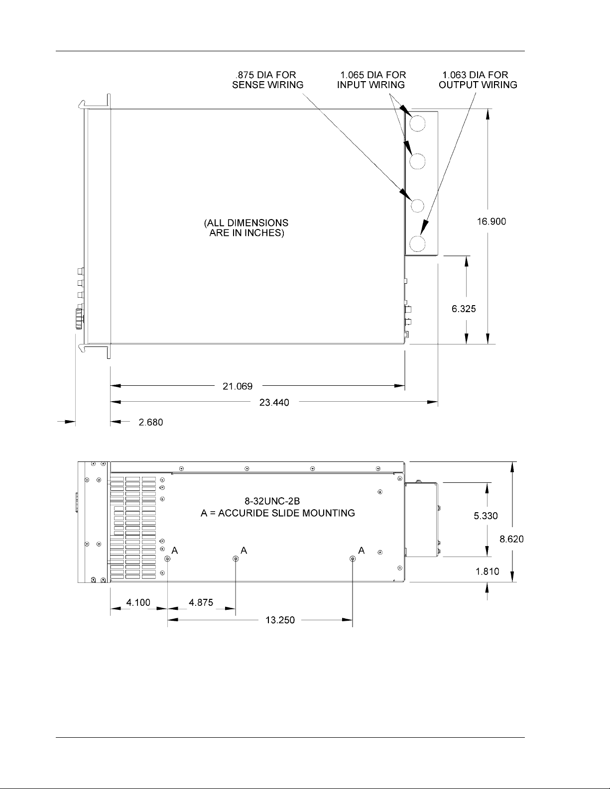
Refer to Table 2–1 for the recommended slides and Figure 2–2 for the mounting
location.
Periodic cleaning is required to ensure that dust build-up within the chassis does not
restrict airflow through the modules, which could lead to overheating of the system. A
strong vacuum cleaner may be used to remove dust from the various assemblies within
the SW chassis. Compressed air is not recommended.
2-2 Operation Manual
Page 29
SW 5250A•SW 3500A•SW 1750A Installation
2.6 Installation/Dimensional Drawing
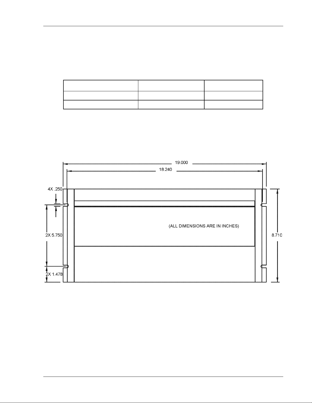
Refer to Figure 2–1 and Figure 2–2 for information on outline and mounting dimensions
of the unit and customer wiring conduit details. Refer to Figure 2–3 and Table 2–2
through Table 2–6 for rear panel connector information.
TYPE MANUFACTURER PART NUMBER
Mounting Kit (for slides) Jonathan BK-3
Slides Accuride C-3307-16D
Table 2–1 Recommended Mounting Slide
Figure 2–1 Mounting Dimensions, SmartWave Front View
Operation Manual 2-3
Page 30
Installation SW 5250A•SW 3500A•SW 1750A
Figure 2–2 Mounting Dimensions, SmartWave Top and Side Views
2-4 Operation Manual
Page 31
SW 5250A•SW 3500A•SW 1750A Installation
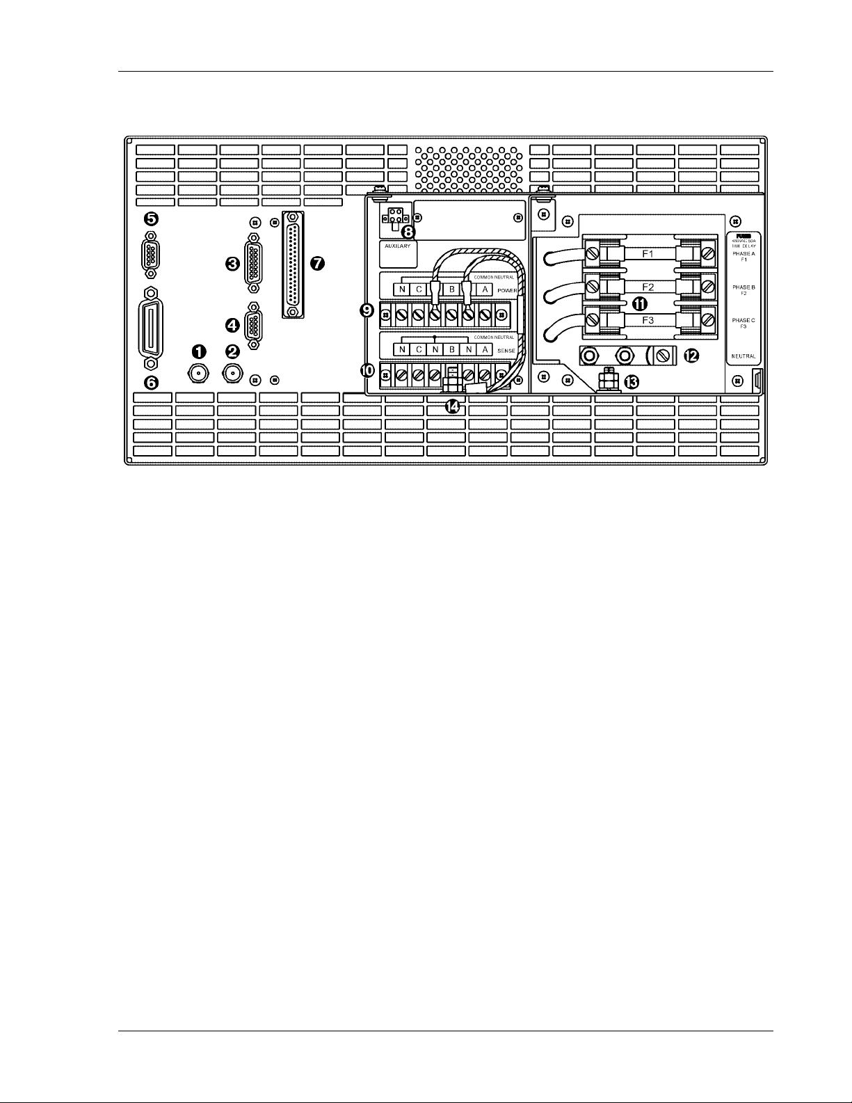
Figure 2–3 SmartWave Rear Panel
Operation Manual 2-5
Page 32
Installation SW 5250A•SW 3500A•SW 1750A
2.7 Input/Output Connectors
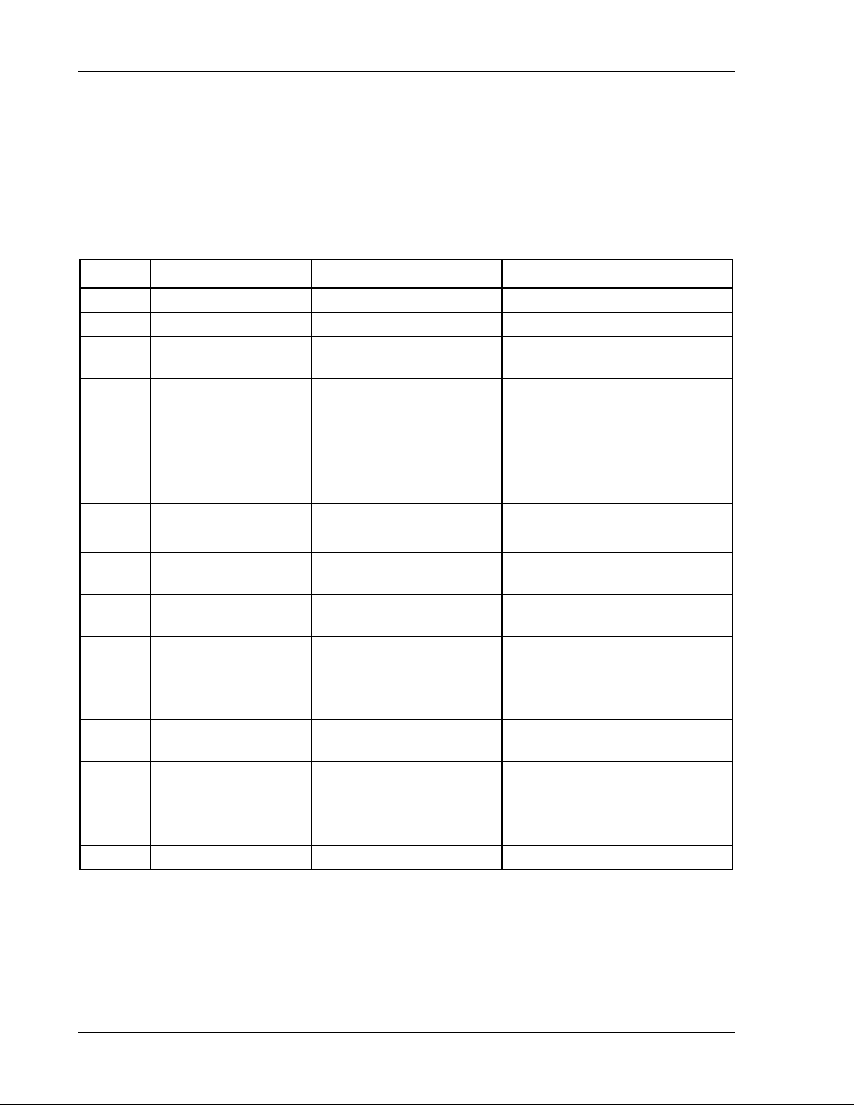
Table 2–2 provides a listing of the SW input and output connectors and other data.
Table 2–3 through Table 2–6 provide specific pinout information.
NOTE: The RS232 AND AUX OUT connectors (Figure 2–3, Items 4 and 8,
respectively) are Elgar proprietary; thus, the pinouts will not be provided.
ITEM # NAME TYPE MANUFACTURER / PART #
1 SYNC OUT BNC KINGS, PN KC-79-179
2 CLOCK & LOCK BNC KINGS, PN KC-79-179
3 EXT IN ±7.5V MAX
4 RS232
5 DFI
6 IEEE 488.2
7 SLAVE 37 POS SUB-D FEMALE ITT CANNON, PN ADC37SOL2
8 AUX OUT 4 POS MINIFIT JR MOLEX, PN 39-29-9045
9
10
11 PHASE B FUSE F2*
OUTPUT POWER
TERMINAL BARRIER
REMOTE SENSE
TERMINAL BARRIER
PHASE A FUSE F1*
PHASE C FUSE F3*
15 POS SUB-D FEMALE
(Gold Contacts)
9 POS SUB-D MALE (Gold
Contacts)
9 POS SUB-D FEMALE
(Gold Contacts)
25 POS FEMALE
(Gold Contacts)
6 POS (#6 HDW)
6 POS (#6 HDW)
480VAC 50A
TIME DELAY
480VAC 50A
TIME DELAY
600VAC 20A
TIME DELAY
AMP, PN 747052-3
AMP, PN 747043-4
AMP, PN 747052-4
AMP, PN 554434-1
MAGNUM,
PN A304106-07-CA-MP8
MAGNUM,
PN A304106-07-CA-MP8
BUSSMAN, SC50
LITTLEFUSE, SLC50
BUSSMAN, SC40
LITTLEFUSE, SLC40
GOULD SHAWMUT ATDR20
LITTLEFUSE CCMR20
INPUT,
12
13 SAFETY GROUND STUD #1/4-20 X .75 LG
14 CHASSIS GROUND STUD #1/4-20 X .75 LG
* Refer to Table 2–7 and Table 2–8 for Fuse Ampere Rating
NEUTRAL LUG,
SINGLE BARREL
90A, 8AWG-2AWG PANDUIT, PN C070-14-Q
Table 2–2 SW Input/Output Connectors (see Figure 2–3)
2-6 Operation Manual
Page 33
SW 5250A•SW 3500A•SW 1750A Installation
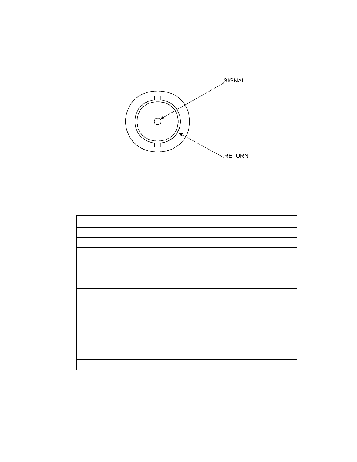
2.7.1 BNC Connectors
The diagram below illustrates the signal and return connections. Refer to Figure 2–3,
Items 1 and 2.
2.7.2 EXT IN (External Input)
Refer to Figure 2–3, Item 3.
PIN # MNEMONIC LEVEL
1 SHIELD CHASSIS
2 SHIELD CHASSIS
3 SHIELD CHASSIS
4 SHIELD CHASSIS
5 SHIELD CHASSIS
6 through 9 Not Used Not Used
10 EXT_IN_A
11 EXT_IN_B
12 EXT_IN_C
13 EXT_RETURN
14 and 15 Not Used Not Used
±7.25 Vpeak
DC to 5000 Hz, ≥30 kΩ
±7.25 Vpeak
DC to 5000 Hz, ≥30 kΩ
±7.25 Vpeak
DC to 5000 Hz, ≥30 kΩ
±20 Vpeak
WRT CHASSIS GROUND
Table 2–3 EXT IN Connector Pinout
Operation Manual 2-7
Page 34
Installation SW 5250A•SW 3500A•SW 1750A
2.7.3 DFI (Direct Fault Indicator)
The DFI connector on the rear panel has both input and output functionality.
The DFI Output Relay indicates a shutdown fault has occurred on the SW. It is a SPST
reed relay with rear panel connections to the normally closed output contacts. When
the SW is operating the relay is energized so that the contacts are open. When a fault
occurs, or if the unit should lose power, the relay closes to indicate a fault has occurred.
The DFI Output Relay will remain latched until the front panel Power switch is cycled.
The DFI Input Signal is used to command the SW to open the Output relay, and close
the DFI relay. It is a TTL-compatible input with a 1 kΩ input impedance, a 10 kΩ pullup
to +5 VDC, and clamping diodes to +5 VDC and ground. A signal with a negative going
edge from +5 VDC to ground will trigger the DFI response.
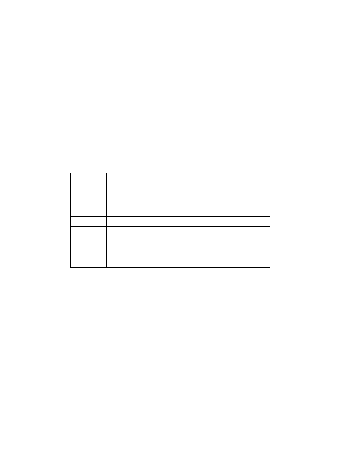
Refer to Figure 2–3, Item 5.
PIN # MNEMONIC LEVEL
1 DFI RLY COMM —
2 Not Used —
3 DFI IN +
4 and 5 Not Used —
6 DFI RLY N.O. —
7 Not Used —
8 DFI IN RTN TTL
9 IEEE 488.2 SIGNAL GND
TTL (10 k
Ω
input impedance)
Table 2–4 DFI Connector Pinout
2-8 Operation Manual
Page 35
SW 5250A•SW 3500A•SW 1750A Installation
2.7.4 IEEE 488.2
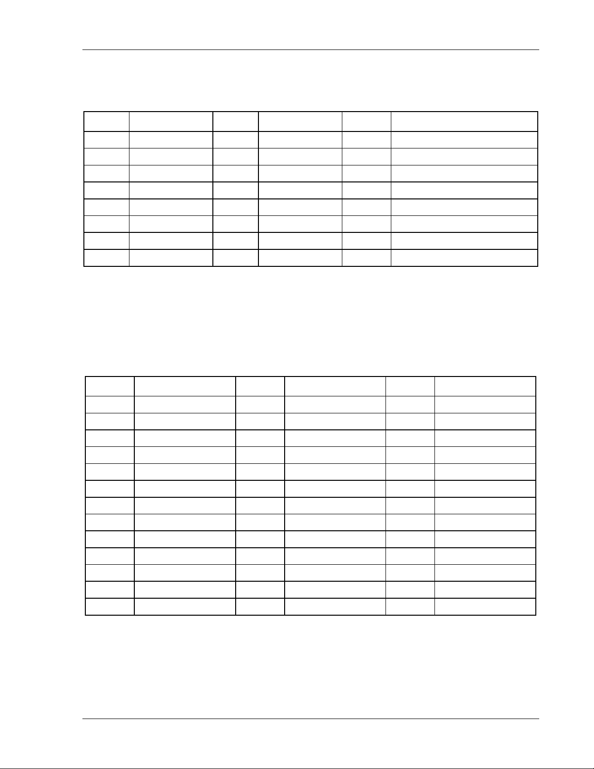
Refer to Figure 2–3, Item 6.
PIN # MNEMONIC PIN # MNEMONIC PIN # MNEMONIC
1 DIO1 9 IFC 17 REN
2 DIO2 10 SRQ 18 GND (TW PAIR W/DAV)
3 DIO3 11 ATN 19 GND (TW PAIR W/NRFD)
4 DIO4 12 SHIELD 20 GND (TW PAIR W/NDAC)
5 EOI 13 DIO5 21 GND (TW PAIR W/IFC)
6 DAV 14 DIO6 22 GND (TW PAIR W/SRQ)
7 NRFD 15 DIO7 23 GND (TW PAIR W/ATN)
8 NDAC 16 DIO8 24 SIGNAL GROUND
Table 2–5 IEEE 488.2 Connector Pinout
2.7.5 Slave Connector
Refer to Figure 2–3, Item 7.
PIN # MNEMONIC PIN # MNEMONIC PIN # MNEMONIC
1 AGND_BUS 14 AGND_BUS 26 -15A_BUS
2 AGND_BUS 15 ISNSC-_BUS 27 AGND_BUS
3 AGND_BUS 16 ISNSB-_BUS 28 +5D_MAS
4 +15A_BUS 17 AGND_BUS 29 AGND_BUS
5 AGND_BUS 18 ISNSA-_BUS 30 DRC+_BUS
6 -15A_BUS 19 NOT USED 31 DRB+_BUS
7 /R1_BUS 20 TSA_BUS 32 AGND_BUS
8 /R0_BUS 21 TSB_BUS 33 DRA+_BUS
9 +5D_MAS 22 TSC_BUS 34 ISNSC+_BUS
10 DRC-_BUS 23 /RST_BUS 35 AGND_BUS
11 AGND_BUS 24 /FAULT_BUS 36 ISNSB+_BUS
12 DRB-_BUS 25 /DC_STOP_BUS 37 ISNSA+_BUS
13 DRA-_BUS
Table 2–6 Slave Connector Pinout
Electrical Specification:
All voltages less than ±20VPK with respect to chassis ground.
Operation Manual 2-9
Page 36
Installation SW 5250A•SW 3500A•SW 1750A
2.7.6 Grounding
The three waveform outputs (TRIGGER OUT, CLOCK & LOCK,
SYNC OUT) share the same ground. This ground should not
exceed ±20V Peak from chassis ground. If possible, this ground
should be connected to the chassis.
DFI and IEEE 488.2 share the same signal ground.
2.8 Input Power Requirements
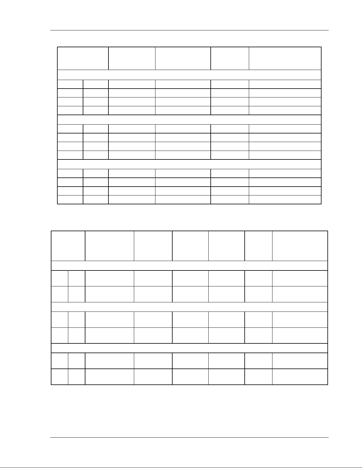
Input power is connected to the SW 5250A, SW 3500A, or SW 1750A via the rear panel
connectors. See Table 2–7 and Table 2–8 for input current values.
WARNING!
An overcurrent protection device (i.e., circuit breaker) is required
in the building installation. The circuit breaker must disconnect
the 3-phase voltages; the neutral must not be disconnected. The
circuit breaker should be rated for continuous current as required
by the SW system (see Table 2–2). Installation should comply with
local safety standards.
A device to disconnect the SW system from the energy supply
source is also required. This switch or circuit breaker must be
close to the SW system, within easy reach of the operator, and
clearly labeled as the disconnection device for the SW system.
2-10 Operation Manual
Page 37
SW 5250A•SW 3500A•SW 1750A Installation
SW 5250A (SW 5250M, SW 5250S)
PFC USA 25A RMS Not Required 40A 40A RMS
PFC INTL 13A RMS 13A RMS 20A 20A RMS
RECT USA 39A RMS Not Required 50A 50A RMS
RECT INTL 39A RMS 68A RMS 50A 50A RMS
SW 3500A
PFC USA 25A RMS Not Required 40A 40A RMS
PFC INTL 13A RMS 13A RMS 20A 20A RMS
RECT USA 26A RMS Not Required 40A 40A RMS
RECT INTL 26A RMS 45A RMS 40A 40A RMS
SW 1750A
PFC USA 14A RMS Not Required 20A 20A RMS
PFC INTL 13A RMS 13A RMS 20A 20A RMS
RECT USA 13A RMS Not Required 20A 20A RMS
RECT INTL 13A RMS 23A RMS 20A 20A RMS
MAXIMUM
LINE
CURRENT
MAXIMUM
NEUTRAL
CURRENT
F1-F3
FUSE
RATING
RECOMMENDED
CIRCUIT BREAKER
RATING (MAX.)
Table 2–7 Input Currents for 3-Phase Input Power
REQ’D INPUT
TERMINAL
JUMPER
CONNECTIONS
SW 5250A
PFC* USA F1 to F2 F1, F3
PFC INTL
SW 3500A
PFC USA F1 & F2 F1, F3
PFC INTL
SW 1750A
PFC USA None F1, F3
PFC INTL None F1, Neutral
F1 to F2,
F2 to F3
F1 to F2,
F2 to F3
* Only Phase A and Phase B are present at the output.
CONNECT 1-
PHASE INPUT
POWER TO
F1, Neutral
F1, Neutral
VOLTAGE
187-264
VRMS, L-L
187-264
VRMS, L-N
187-264
VRMS L-L
187-264
VRMS L-N
187-264
VRMS L-L
187-264
VRMS L-N
MAXIMUM
INPUT
CURRENT
28A RMS 40A 40A RMS
42A RMS 20A 40A RMS
28A RMS 40A 40A RMS
28A RMS 20A 40A RMS
14A RMS 20A 20A RMS
14A RMS 20A 20A RMS
F1-F3
FUSE
RATING
RECOMMENDED
CIRCUIT BREAKER
RATING (MAX.)
Table 2–8 Single-Phase Input Configurations
Operation Manual 2-11
Page 38
Installation SW 5250A•SW 3500A•SW 1750A
2.8.1
Connect the input wires to the phase A (F1), B (F2), and C (F3) input fuse terminals
(no Neutral is required). Ensure that the chassis safety ground is also connected.
Use cables with ratings equal to or greater than the current rating listed on the unit or in
Table 2–7. Any phase sequence of wiring can be used.
2.8.2
It is essential that the Neutral connection is present when using the unit. An external
circuit breaker is required for the 3-phase voltages. Do not pass Neutral through the
breaker. Only units that are factory set at this voltage will operate at this voltage.
Connect the input wires to phases A (F1), B (F2), C (F3) and Neutral. Ensure that the
chassis safety ground is also connected. Use cables with ratings equal to or greater
than the current rating listed on the unit or in Table 2–7.
187 to 264 VRMS L–L 3-Phase Operation (3-Wire USA)
342 to 457 VRMS L–L 3-Phase Operation (4-Wire INTL)
CAUTION!
Neutral must not be broken by an external switch. Severe damage to
the unit may occur if Neutral is broken and phase voltage is present.
2.8.3 Single-Phase Input Connections
The SW system is designed for three-phase input power operation, either 3-wire (USA)
or 4-wire (EUR) plus a chassis safety ground. However, if only single-phase input
power is available, the configurations listed in Table 2–8 are possible.
An overcurrent protection device and a device for disconnecting the single-phase
energy supply source are required as indicated in Section 2.8 above.
2-12 Operation Manual
Page 39
SW 5250A•SW 3500A•SW 1750A Installation
2.9
2.9.1
Output Connections to the Load
SW 5250A Output Connections
The Model SW 5250A can power 1-phase, 2-phase and 3-phase loads. Local or
remote sensing can be used; if no sense lines are connected, the unit automatically
reverts to local sense. Outputs may be directly paralleled for greater power. If the
outputs are paralleled it is important to program the unit to the parallel mode before
shorting the outputs together (refer to Figure 2–4). Outputs cannot be placed in series
since the Neutral is common. However, by programming two phases 180° apart, double
voltage, single phase is achieved.
Any phase sequence of wiring can be used.
The sense Neutral is also common. Thus, it is important to wire the sense wires
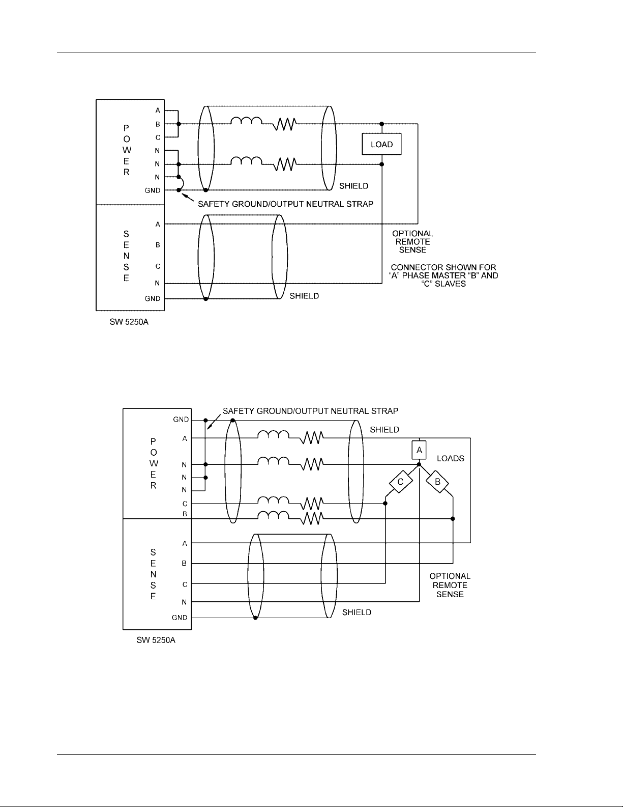
properly (refer to Figure 2–5). If remote sense is used:
Sense A is connected to Power A;
•
Sense B is connected to Power B;
•
Sense C is connected to Power C; and
•
Neutral Sense is connected to Neutral Power.
•
The three waveform outputs (TRIGGER OUT, CLOCK & LOCK,
SYNC OUT) share the same ground. This ground should not
exceed ±20V Peak from chassis ground. If possible, this ground
should be connected to the chassis.
Output power neutral must be connected to chassis ground for
safe operation. The SW system is shipped with a green/yellow wire
connected from output power neutral to chassis ground.
It is important that the Neutral not be >20V away from the chassis
potential; the unit will shut down if this voltage is exceeded.
If a transformer or inductive load is present, the unit should be programmed to AC. This
prevents small amounts of DC being generated, which may saturate the magnetics.
For best performance, the sense leads should be connected and output neutral should
be connected to chassis ground.
Operation Manual 2-13
Page 40
Installation SW 5250A•SW 3500A•SW 1750A
Figure 2–4 Parallel Connections
Figure 2–5 Sense Lead Connections for 3-Phase Output
2-14 Operation Manual
Page 41

SW 5250A•SW 3500A•SW 1750A Installation
The output power and sense leads should be shielded and the shield connected to the
chassis to prevent noise pickup (or radiation to sensitive circuits in the vicinity). Again,
the shield should be connected to chassis ground.
Due to the high voltages present, 312 VRMS line-to-neutral and 437 VRMS line-to-line
cables rated to these voltages must be used for both the Power and Sense leads.
2.9.2
The Model SW 3500A has phase A and phase B present; phase C is an open circuit.
Make connections as for the SW 5250A but with phase C missing.
The Model SW 1750A has only phase A present; phases B and C are open circuits.
2.9.3
Due to the high voltages and frequencies involved, it is recommended that all input and
output wiring is protected with flexible conduit. Holes for this purpose are made in the
terminal box (see Figure 2–2). All wiring must meet local standards for safety.
2.10
The following guidelines assist in determining the optimum cable specification for
your power applications. These guidelines are equally applicable to both DC and low
frequency AC (up to 450 Hz) power cabling. The same engineering rules apply whether
going into or out of an electrical device. Thus, this guide applies equally to the input
cable and output cable for this Elgar instrument and application loads.
SW 3500A and SW 1750A Output Connections
Wiring of Unit
Wire Gauge Selection
Power cables must be able to safely carry maximum load current without overheating or
causing insulation destruction. It is important to everyday performance to minimize IR
(voltage drop) loss within the cable. These losses have a direct effect on the quality of
power delivered to and from instruments and corresponding loads.
When specifying wire gauge, the operating temperature needs to be considered. Wire
gauge current capability and insulation performance drops with the increased
temperature developed within a cable bundle and with increased environmental
temperature. Thus, short cables with generously derated gauge and insulation
properties are recommended for power source applications.
Avoid using published commercial utility wiring codes. These codes are designed for
the internal wiring of homes and buildings and accommodate the safety factors of wiring
loss, heat, breakdown insulation, aging, etc. However, these codes consider that up to
5% voltage drop is acceptable.
Operation Manual 2-15
Page 42
Installation SW 5250A•SW 3500A•SW 1750A
Such a loss directly detracts from the quality performance specifications of this Elgar
instrument. Frequently, these codes do not consider bundles of wire within a cable
arrangement.
In high performance applications, as in motor start-up and associated inrush/ transient
currents, additional consideration is required. The cable wire gauge must consider peak
voltages and currents, which may be up to ten times the average values. An underrated
wire gauge adds losses, which alter the inrush characteristics of the application and
thus the expected performance.
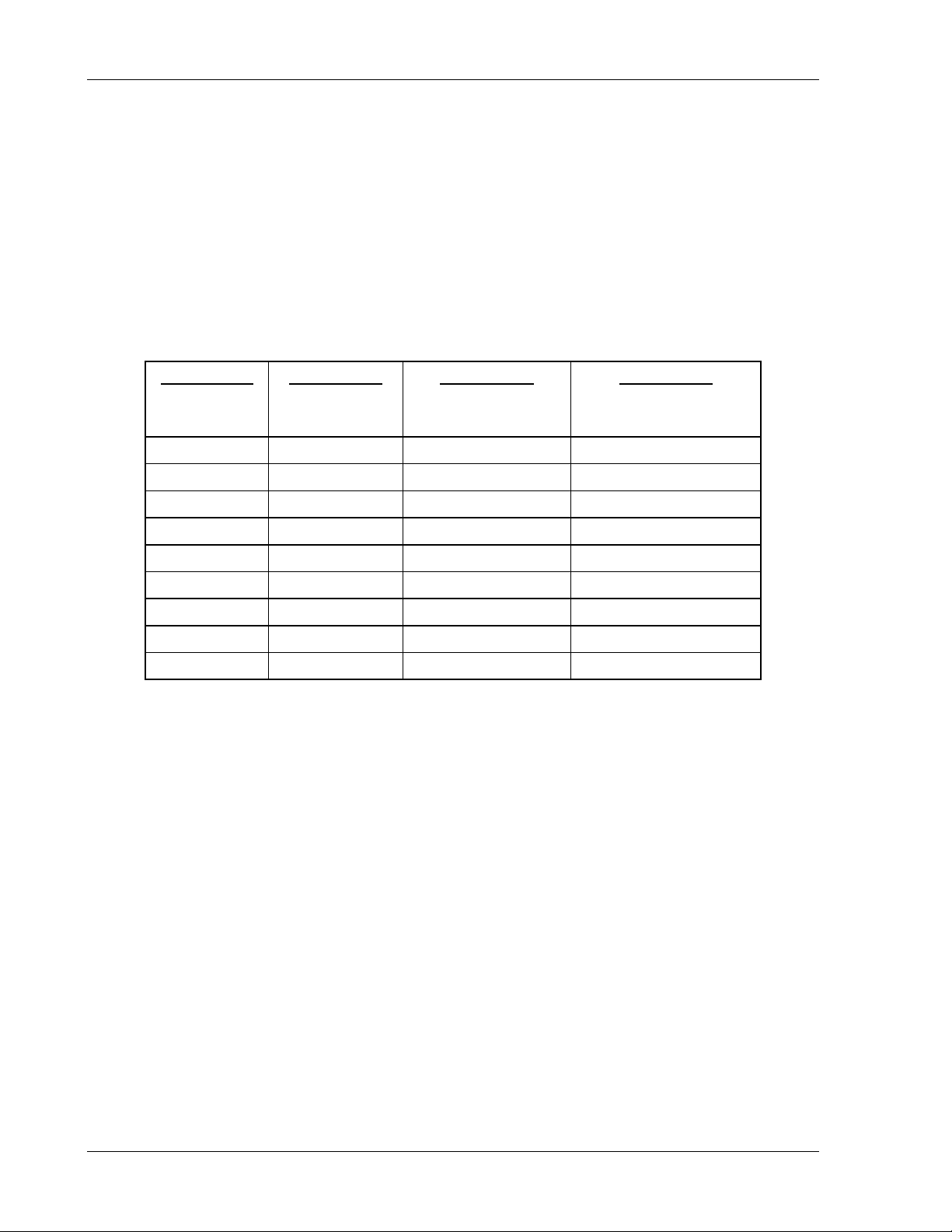
Table 2–9 identifies popular ratings for DC and AC power source cable wire gauges.
OLUMN
C
SIZE
(AWG)
1:
14 15 0.257 3.85
12 20 0.162 3.24
10 30 0.102 3.06
8 40 0.064 2.56
6 55 0.043 2.36
4 70 0.025 1.75
2 95 0.015 1.42
1/0 125 0.010 1.25
3/0 165 0.006 1.04
OLUMN
C
AMPERES
(MAXIMUM)
2:
OLUMN
C
OHMS/100 FEET
(ONE WAY)
3:
OLUMN
C
IR DROP/100 FEET
(COL. 2 X COL. 3)
4:
Table 2–9 Recommended Wire Gauge Selection Guide
2-16 Operation Manual
Page 43

SW 5250A•SW 3500A•SW 1750A Installation
The following notes apply to Table 2–9 and to the power cable definition:
1. The above figures are based upon insulated copper conductors at 25°C (77°F),
two current carrying conductors in the cable plus a safety (chassis) ground.
Columns 3 and 4 refer to “one way” ohms and IR drop of current carrying
conductors (e.g., a 50-foot cable contains 100 feet of current carrying conductor).
2. Determine which wire gauge for the application by knowing the expected peak
load current (I
), the maximum tolerated voltage loss (V
peak
) within the cable,
loss
and the one way cable length.
The formula below determines which ohms/100 feet entry is required from
Column 3. Read the corresponding wire gauge from Column 1.
(Column 3 value) =
V
/[I
loss
x 0.02 x (cable length)]
peak
Where:
Column 3 value =
Entry of the table above.
Cable length =
One way cable length in feet.
V
=
loss
Maximum loss, in volts, permitted within cable.
Special case
: Should the V
requirement be very loose, I
loss
may exceed the
peak
maximum amperes (Column 2). In this case, the correct wire gauge is selected
directly from the first two columns of the table.
Example:
drop (V
A 20 ampere (I
) along its 15-foot cable (one way cable length) requires (by formula)
loss
) circuit which may have a maximum 0.5 volt
peak
a Column 3 resistance value of 0.083. This corresponds to wire gauge size 8
AWG.
If the cable length was 10 feet, the Column 3 value would be 0.125 and the
corresponding wire gauge would be 10 AWG.
Operation Manual 2-17
Page 44

Installation SW 5250A•SW 3500A•SW 1750A
3. Aluminum wire is not recommended due to soft metal migration at the terminals,
which may cause long term (on the order of years) poor connections and
oxidation. If used, increase the wire gauge by two sizes (e.g., specify 10 gauge
aluminum instead of 14 gauge aluminum).
4. Derate the above wire gauge (use a heavier gauge) for higher environmental
temperatures since conductor resistance increases with temperature.
Temperature
Current Capability
40°C, 104°F 80%
5. Derate the above wire gauge (use a heavier gauge) for an increased number of
current carrying conductors. This offsets the thermal rise of bundled conductors.
Number of Current
Conductors
Capability
3 to 6 80%
Above 6 70%
6. The preferred insulation material is application dependent. Elgar's recommendation is any flame retardant, heat resistant, moisture resistant thermoplastic
insulation rated to a nominal 75°C (167°F). Voltage breakdown must exceed the
combined effects of:
The rated output voltage;
•
Transient voltages induced onto the conductors from any source;
•
The differential voltage to other nearby conductors; and,
•
Safety margins to accommodate degradations due to age, mechanical
•
abrasion, and insulation migration caused by bending and temperature.
7. As frequency increases, the magnetic field of the current carrying conductors
becomes more significant in terms of adverse coupling to adjacent electrical
circuits. Use twisted pairs to help cancel these effects. Shielded twisted pairs
are even better. Avoid close coupling with nearby cables by using separate
cable runs for high power and low power cables.
8. The above general values and recommendations should be reviewed, modified
and amended as necessary, for each application. Cables should be marked with
appropriate safety WARNING decals as hazardous voltages may be present.
2-18 Operation Manual
Page 45
SECTION 3
OPERATION
3.1
The following is an overview of the controls and display for the SmartWave unit.
Context-sensitive help is available from the front panel by pressing the Help key.
3.2
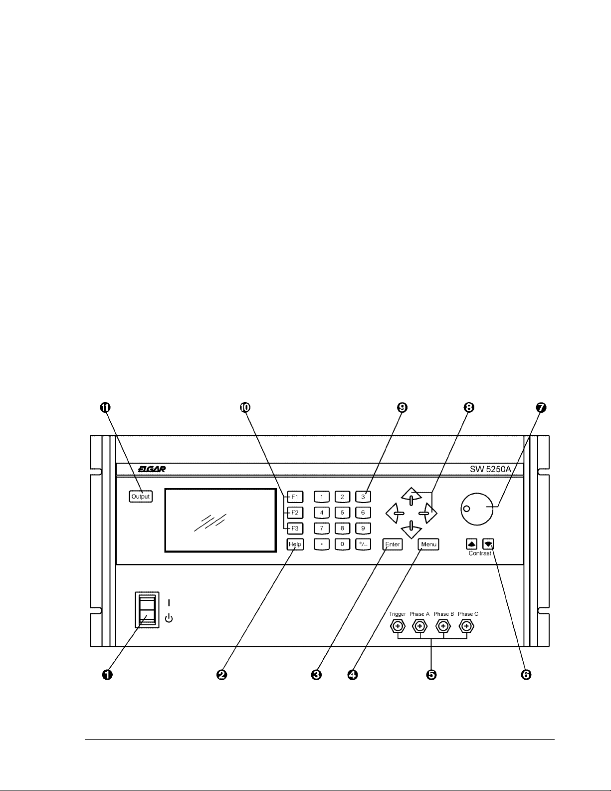
The SW front panel is used for programming and data entry in local mode operation.
The front panel is shown in Figure 3–1, followed by a description of each of the controls.
Introduction
Front Panel Controls
Figure 3–1 Front Panel Controls (SW 5250A)
Operation Manual 3-1
Page 46

Operation SW 5250A•SW 3500A•SW 1750A
POWER ON/STANDBY SWITCH. Pressing the top portion of the switch turns
power on; pressing the bottom portion of the switch places the unit in the
STANDBY mode.
When power is turned on, the unit goes through the power up cycle. This cycle
may last between 30 seconds and five minutes, depending on the amount of
software that needs to be loaded and conditioned. The Elgar logo will be
displayed during the power up cycle.
NOTE: To prevent large inrush currents flowing while resetting the SW, allow
several seconds before cycling power, especially if power is cycled via an
external circuit breaker.
HELP KEY. Press this key to access a help screen for the menu item currently
displayed. Help screens may contain information not found in this manual.
ENTER KEY. Press this key to:
Go to the next menu level on the LCD display
•
Enter the incr./dec. mode using the knob or arrow keys
•
Accept a numeric entry via the keypad and/or knob
•
Accept a name in text mode entry.
•
MENU KEY. Press this key to go to the previous menu level, to abort editing a
data entry field when using the numeric keypad, or to switch from remote to local
mode.
WAVEFORM MONITOR BNCs. Trigger output provides a synchronization pulse
(see Table 3.1, SYNC). Phases A, B, and C provide scaled outputs for
monitoring drive signals to output amplifiers.
CONTRAST KEYS. These keys, located below the knob, are used to adjust the
contrast of the display. Press and hold the left key to decrease the contrast;
press and hold the right key to increase the contrast to the desired level.
KNOB. Use the rotary knob for data entry and for slewing of voltage and
frequency. The knob serves the same function as the Up/Down Arrow keys.
There are three knob thresholds which increment by 0.1, 1.0, or 10.0, depending
on the speed of the rotation.
ARROW KEYS. The Up and Down Arrow keys are used to move between
menu selections on the current page displayed and to increase or decrease
values in the incr./dec. mode.
Left Arrow Key. This key returns to the previous menu level (a shortcut for the
Menu key) and, in the text mode or numeric entry, acts as a backspace.
Right Arrow Key. This key moves you to the next menu level (a shortcut for the
Enter key) and, in the text mode, accepts the current character.
3-2 Operation Manual
Page 47
SW 5250A•SW 3500A•SW 1750A Operation
KEYPAD. The 12-key keypad is used to enter numeric values (0 through 9), a
decimal point (when required), and to change the polarity of the selection via the
+/- key.
For example, to enter an amplitude value of “-139.2,” enter 1, 3, 9, decimal point,
2; press the +/- key to change the polarity; then press the Enter key to accept the
value.
FUNCTION KEYS F1 THROUGH F3. Functions of these keys depend on the
selected menu item and is defined in the Help screens.
OUTPUT KEY. This key activates/deactivates the output relay. The status of
the output relay is indicated as “OUTPUT [ON]” or “OUTPUT [OFF]” on the top
line of the LCD display.
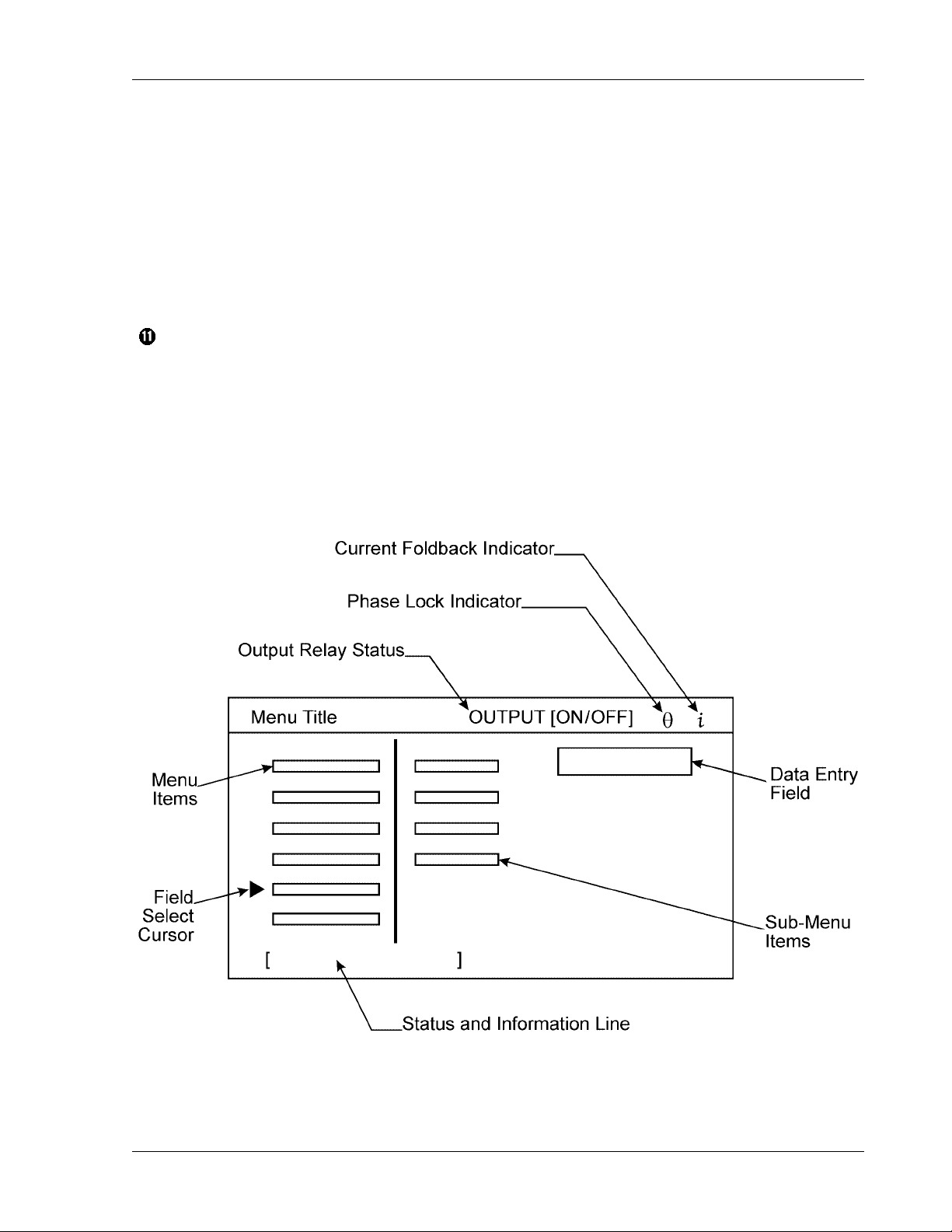
3.3 Menus
The backlit graphics LCD screen displays menus, data entry fields, and status
information in the general format shown below.
Operation Manual 3-3
Page 48
Operation SW 5250A•SW 3500A•SW 1750A
Use the Enter and Menu keys or the Right/Left Arrow keys to move between
•
the menus.
Use the Up/Down Arrow keys to cycle through the items within a specific menu.
•
When you select an item, you can enter data in two ways: (1) Use the keypad to
•
type in the data, or (2) press the Enter key to place a box around the value area,
then use the Up/Down Arrow keys or the Knob to select the data to be entered.
Press the Enter key to accept the data.
•
3.3.1 MAIN MENU
The MAIN MENU consists of the sub-menus listed below.
MAIN MENU OUTPUT [OFF]
PROGRAM
MEASURE
WAVEFORM
SEQUENCE
INSTR
SYSTEM
MAIN MENU Status and Information Data:
Menu Item
Status and Information Line
PROGRAM [interactive programming]
MEASURE [measurement system]
WAVEFORM [create/edit waveform]
SEQUENCE [create/edit sequences]
INSTR [instrument configuration]
SYSTEM [system configuration]
3-4 Operation Manual
Page 49
SW 5250A•SW 3500A•SW 1750A Operation
3.3.2 PROGRAM Menu
The PROGRAM menu allows you to:
Select a phase
•
Program amplitude
•
Program current limit
•
Program frequency
•
Program phase offset (phase offset represents a phase lead with respect to the
•
internal reference)
Select a function to be output on the selected phase.
•
MAIN MENU OUTPUT [OFF]
PROGRAM
MEASURE
WAVEFORM
SEQUENCE
INSTR
SYSTEM
PHASE A (or B or C)
AMPL V
CURL A
FREQ Hz
θ
ANG Deg
FUNC
PROGRAM Menu Status and Information Data:
Menu Item
Status and Information Line Range/Default
PHASE A [<enter> for next phase] Phases A, B, C
AMPL [program output RMS/DC voltage] * 0–156 V or 0–312 V
(default: 0.00V)
CURL [program RMS/DC current limit] 0–13 A or 0–6.5 A (default: 5.00A
dependent on voltage range)
FREQ
θ ANG
[program output frequency]
**
[program phase angle offset] *** 0–360° (default: 0°, 120°, 240°
40–5000 Hz (default: 60 Hz)
dependent on phase selected)
FUNC
[program output waveform]
****
Default: Sine
Operation Manual 3-5
Page 50

Operation SW 5250A•SW 3500A•SW 1750A
Reference Section 3.4, Front Panel Programming Conventions.
*
There is only one frequency setting for all three phases. Changing the frequency
**
of one phase changes the frequency for all phases.
The SW can accept only positive numbers when programming phase angle
***
offset. Because phase angle offset represents a phase lead with respect to the
internal reference, the formula below should be used for a selected phase to
represent phase angle in terms of phase lag:
Desired Phase Angle Lag = 360° – (Ph.B θ Angle – Ph.A θ Angle)
The examples below are for a two–phase quadrature system:
For phase angles Ph.A = 0°, Ph.B = 270°, phase lag would be 90°.
•
90° = 360° – (270° – 0°)
For phase angles Ph.A = 45°, Ph.B = 120°, phase lag would be 285°.
•
285° = 360° – (120° – 45°)
To operate the SW as a DC supply, select the function as “DC+” or “DC-” for
****
positive and negative DC. “AC+DC Coupling” must also be selected from the
INSTRUMENT menu. The AMPL field is programmed to 0V as a precaution
when changing to or from the “DC+” or “DC-” function.
3.3.2.1 Locking Program Fields
For two- or three-phase systems, individual programming fields of amplitude, current
limit, phase angle, and function may be “locked” so that any change made to phase A
will be made to phases B and C. The Lock function is intended for front panel
operation. When using GPIB, use the SOURCE0 command.
To lock a field:
1. Move the field select cursor to the field to be locked in the Phase A Program
menu.
2. Press the F1 function key. The “¥” symbol should appear to the right of the field
indicating the lock mode is active.
3. Enter the value to be locked into the field.
NOTE: The lock will not be active until a value is entered; previously entered
values are not locked.
To unlock a field:
1. Move the field select cursor to the locked field in the Phase A Program menu.
2. Press the F1 function key. The “¥” symbol should disappear.
3-6 Operation Manual
Page 51

SW 5250A•SW 3500A•SW 1750A Operation
3.3.2.2 Front Panel Store/Recall
The current state of the SW can be saved and restored using the Front Panel
Store/Recall feature. The following Program Menu parameters are affected:
• Amplitude
• Current Limit
• Frequency
• Phase Angle
• Function
The Store/Recall Menu can be accessed by pressing F2 from any Program menu edit
field. Setups are stored/recalled as a number from 0 to 49. The incr./dec. mode is not
available for this menu. Store/Recall functions do not affect the Lock/Unlock status of
the Program menu fields. If a field is locked, it will remain locked. However, the Recall
parameters for phases B and C will be updated
To store a setup:
1. Press F2 from any Program menu edit field.
2. Move the field select cursor to “STORE SETUP.”
3. Enter a setup number from 0 to 49.
To recall a setup:
1. Press F2 from any Program menu edit field.
2. Move the field select cursor to “RECALL SETUP.”
3. Enter the previously stored setup number from 0 to 49.
Operation Manual 3-7
Page 52
Operation SW 5250A•SW 3500A•SW 1750A
3.3.3 MEASURE Menu
If equipped with the Test and Measurement option, the MEASURE menu allows you to:
Measure voltage (RMS)
•
Measure current (RMS)
•
Measure frequency
•
Measure phase angle (referenced to a master)
•
Measure power (W)
•
Measure apparent power (VA)
•
Measure power factor (PF)
•
Measure peak current.
•
MAIN MENU OUTPUT [OFF]
PROGRAM
MEASURE
WAVEFORM
SEQUENCE
INSTR
SYSTEM
AMPL A 120.00 V
OFF 0.00
OFF 0.00
OFF 0.00
OFF 0.00
OFF 0.00
The Measure menu contains six display fields that can be set to any of the available
measurements. To set a measurement field:
1. Move the field select cursor to one of the six measurement fields.
2. Press <Enter>. A pop-up window entitled SELECT MEASUREMENT will
appear; OFF will be selected.
3. Press the Up/Down Arrow keys or use the Knob to scroll through the list of
available measurements.
4. With the desired measurement in the selection window (or OFF to disable a
measurement), press <Enter>.
The measured value will be displayed in the display field. Active measurement fields
are continually updated and retained upon cycling power to the unit.
3-8 Operation Manual
Page 53
SW 5250A•SW 3500A•SW 1750A Operation
3.3.4 WAVEFORM Menu
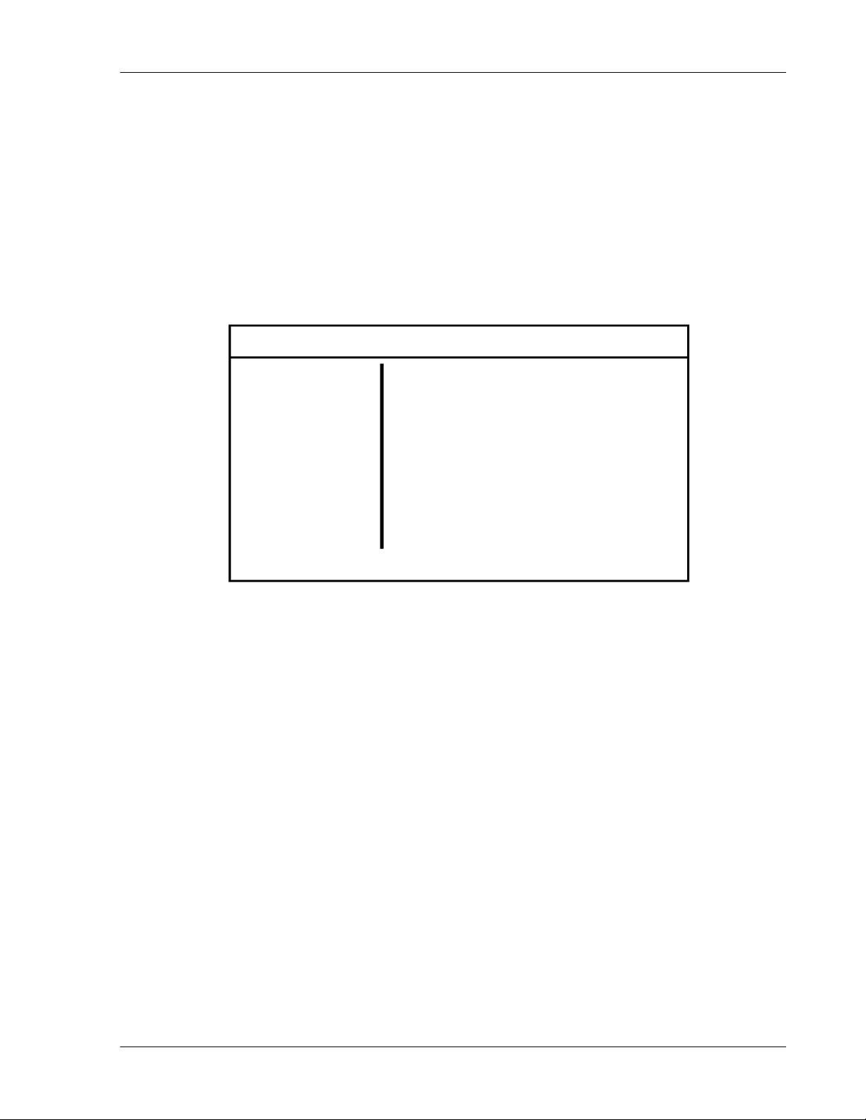
The WAVEFORM menu allows you to perform a variety of actions on waveshapes
and waveforms, including the creation of a new waveform based on a waveshape in
memory.
The waveshapes and waveforms are limited to spikes, dropouts, sags and surges
of existing waveforms in the scratchpad area. This is accomplished by loading the
existing waveshape into the waveform scratchpad then editing it. The edited waveform
may then be viewed, output using the SCRATCH function name in the PROGRAM
menu, or saved to the waveform library.
WAVEFORM OUTPUT [OFF]
LOAD
EDIT
VIEW
SAVE
DELETE
Operation Manual 3-9
Page 54
Operation SW 5250A•SW 3500A•SW 1750A
3.3.4.1 LOAD Sub-Menu
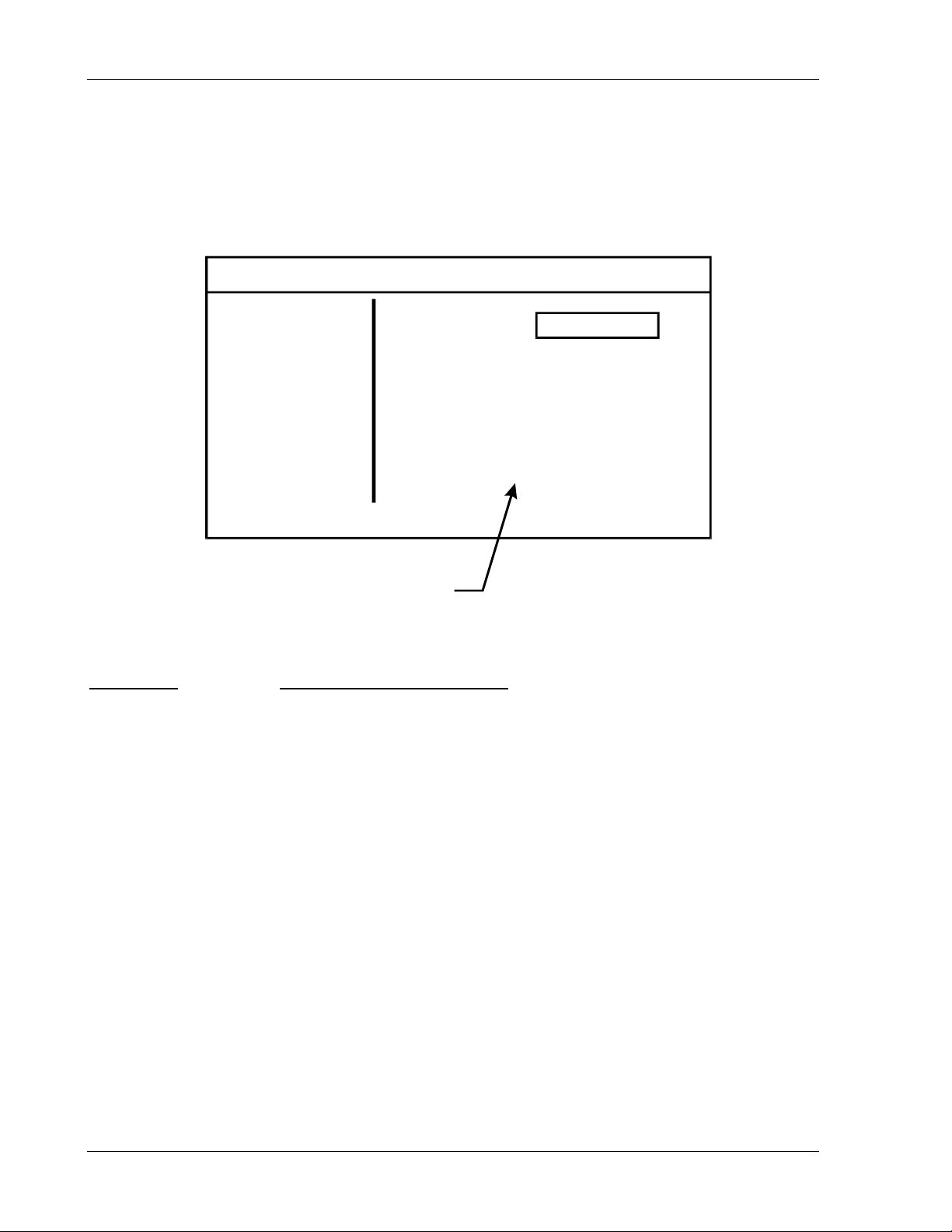
The WAVEFORM menu allows you to LOAD an existing waveform from non-volatile or
flash memory to the waveform scratchpad.
Any existing information in the scratchpad is erased when a new waveform is loaded.
WAVEFORM OUTPUT [OFF]
LOAD
EDIT
VIEW
SAVE
DELETE
Displays library of waveforms
LOAD Sub-Menu Status and Information Line Data:
Menu Item
FUNC [<enter> to select waveform]
Press the Up/Down Arrow keys or use the Knob to scroll through the list of available
waveforms. With the desired waveform in the selection window, press <Enter>.
Status and Information Line
FUNC
Name
3-10 Operation Manual
Page 55
SW 5250A•SW 3500A•SW 1750A Operation
3.3.4.2 EDIT Sub-Menu
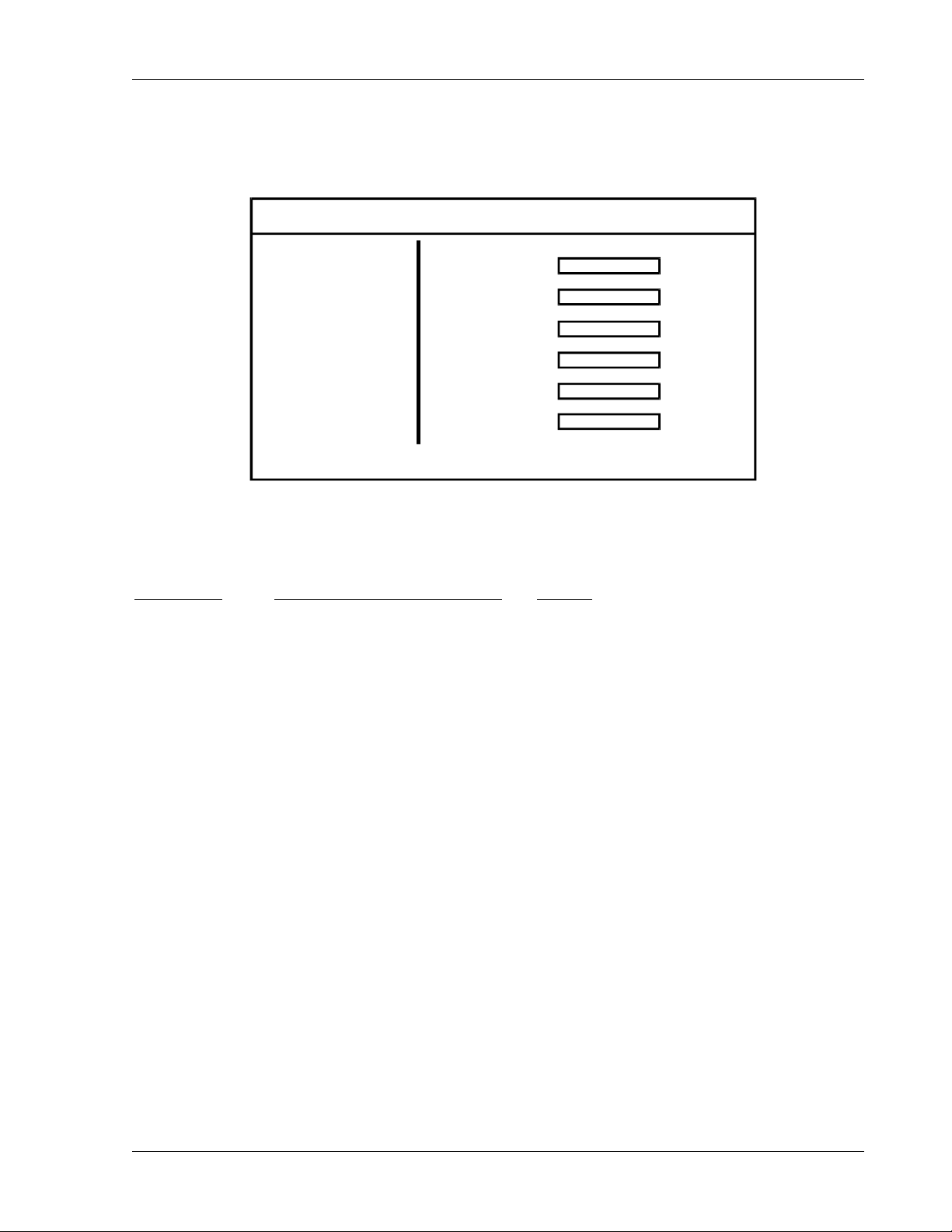
The WAVEFORM menu allows you to EDIT a waveform in the scratchpad.
WAVEFORM OUTPUT [OFF]
LOAD
EDIT
VIEW
SAVE
DELETE
EDIT Sub-Menu Status and Information Data:
Menu Item
FREQ [waveform frequency] 40–5000 Hz
Vrms [output waveform voltage] 0–156 or 0–312 V
START [starting phase angle] 0–360°
Status and Information Line Range
FREQ Hz
Vrms V
START Deg
TIME ms
STOP Deg
AMPL V
TIME [surge/sag duration] 0–1/Freq
STOP [ending phase angle] Start–360°
AMPL [drop/spike voltage] -220.6 to 220.6 Vpeak (156 Vrms range)
-441.2 to 441.2 Vpeak (312 Vrms range)
NOTE: Vrms is in terms of RMS voltage while AMPL is in terms of peak voltage.
Both of these values depend on the selected voltage range setting in
the INSTRUMENT menu.
See the example in section 3.5.1.
Operation Manual 3-11
Page 56
Operation SW 5250A•SW 3500A•SW 1750A
p
3.3.4.3 VIEW Sub-Menu
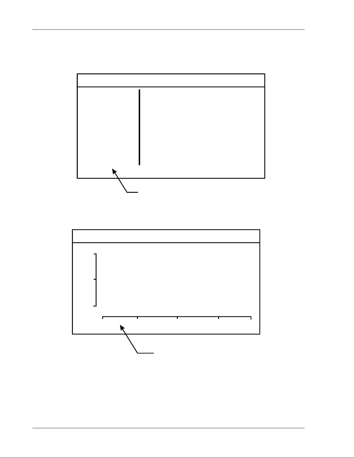
The WAVEFORM menu allows you to VIEW a waveform:
WAVEFORM OUTPUT [OFF]
LOAD
EDIT
VIEW
SAVE
DELETE
Selecting VIEW will display the wave form
in the scratch
ad as shown below.
WAVEFORM OUTPUT [OFF]
4
2
4
21or
2
0
4
2
4
or
2
2
1
90 180 270
Basic display after selecting VIEW
The minimum and maximum Vpeak values displayed on the
vertical axis (either -442 to +442 or -221 to +221) are based on
the selected voltage range setting in the INSTRUMENT menu.
3-12 Operation Manual
Page 57
SW 5250A•SW 3500A•SW 1750A Operation
3.3.4.4 SAVE Sub-Menu
The WAVEFORM menu allows you to assign a name to a new waveform and SAVE it
from the scratchpad to non-volatile memory.
1. Use the Up/Down Arrow keys or the Knob to enter the custom waveform name.
Press the Right Arrow key to proceed to the next character; press the Left
Arrow key to backspace. The last character must be “–”.
2. Press the Enter key.
3. Go to SAVE or SAVE RMS and press the Enter key to save.
WAVEFORM OUTPUT [OFF]
LOAD
EDIT
VIEW
SAVE
DELETE
SAVE Sub-Menu Status and Information Data:
Menu Item
NAME [–> = next char, <– = backsp]
SAVE [save waveform to library]
Status and Information Line
The waveform is saved and scaled in scratch memory
without regard to the calculated RMS value.
NAME –
SAVE
SAVE RMS
SAVE RMS [save waveform to library]
The waveform is scaled so that the calculated RMS
value of the entire waveform is equal to the value of
the Vrms field in the WAVEFORM EDIT menu.
Operation Manual 3-13
Page 58
Operation SW 5250A•SW 3500A•SW 1750A
3.3.4.5 DELETE Sub-Menu
The WAVEFORM menu allows you to DELETE a waveform stored in non-volatile
memory.
ALL USER WAVEFORMS - Erases the 50 user waveform locations in non-volatile
RAM. Any user waveforms currently running will not be deleted.
INITIALIZE MEMORY - Resets the waveform library to the factory settings. All factory
waveforms will be restored and all user waveforms stored in non-volatile RAM will be
erased. You must cycle power to the unit after this function for the changes to take
effect.
NOTE: Under normal operating conditions this function is not required.
Instead, use “Delete–All User Waveforms.”
WAVEFORM OUTPUT [OFF]
LOAD
EDIT
VIEW
SAVE
DELETE
Press key to
toggle custom waveforms
DELETE Sub-Menu Status and Information Data:
Menu Item
FUNC [<enter> to select waveform]
ALL USER WAVEFORMS [<enter> for all user waveforms]
Status and Information Line
Right Arrow
FUNC
ALL USER WAVEFORMS
INITIALIZE MEMORY
Name
INITIALIZE MEMORY [Resets to factory defaults]
NOTE: If you attempt to delete a waveform in Flash Memory,
the message “! - STANDARD WAVEFORM” will appear.
3-14 Operation Manual
Page 59
SW 5250A•SW 3500A•SW 1750A Operation
3.3.5 SEQUENCE Menu
The SEQUENCE menu allows you to create, edit, and execute a sequence.
SEQ MENU OUTPUT [OFF]
LOAD
EDIT
SAVE
DELETE
EXECUTE
3.3.5.1 LOAD Sub-Menu
The SEQUENCE menu allows you to LOAD an existing sequence from non-volatile or
flash memory to the sequence scratchpad.
NEW - Erases all segments in the SEQUENCE scratchpad.
SEQ MENU OUTPUT [OFF]
LOAD
EDIT
SAVE
DELETE
EXECUTE
SEQ
NEW
Name
LOAD Sub-Menu Status and Information Data:
Menu Item
SEQ [load sequence to scratchpad]
NEW [clear sequence scratchpad]
Operation Manual 3-15
Status and Information Line
Page 60
Operation SW 5250A•SW 3500A•SW 1750A
3.3.5.2 EDIT Sub-Menu
The SEQUENCE menu allows you to EDIT a sequence in the scratchpad. Frequency
or amplitude can be ramped over the segment duration.
SEQ EDIT OUTPUT [OFF]
SEG
CYC
A
B
C
EDIT Sub-Menu Status and Information Line Data:
Menu Item
SEG [select segment number] 0–999
FREQ [output frequency in Hz] 40–5000 Hz
CYC [# of cycles, F1 toggles SYNC] 0–9999
Status and Information Line Range
0
0
AMPL
0.00
0.00
0.00
FREQ
TIME
FUNC
Sine
Sine
Sine
60.00
0.00
ms
ANGL
θ
0.00
120.00
240.00
TIME [segment execution time] 0–9999 ms/sec/min
AMPL [amplitude] 0–156 or 0–312 V
FUNC [output waveform] See Section 3.4, Front Panel
Programming Conventions
θ ANGL [phase θ angle (degrees)]
The Step symbol refers to a voltage or frequency “step” in which the voltage or
frequency value in the current segment immediately steps to the specified value in the
next segment. By moving the field select cursor to the Step symbol and pressing
<Enter>, the Up/Down Arrow keys can be used to change the Step signal to the Ramp
symbol to indicate a voltage or frequency ramp. When Ramp is selected, the values in
the current segment are the starting values of the ramp. The voltage or frequency value
of the next segment are the ending values of the ramp. The SW will calculate an
integral number of voltage or frequency steps, over the time period of the current
segment (value specified in the Time field), to reach the values specified in the following
segment.
3-16 Operation Manual
0–360°
Page 61

SW 5250A•SW 3500A•SW 1750A Operation
A ramp must always consist of at least two segments so that starting and ending
•
values can be specified.
Ramps can be increasing or decreasing in value.
•
Voltage and frequency ramping is available; phase angles cannot use the
•
ramping function.
Voltage ramping for Phase A, Phase B, Phase C, and Frequency are all
•
independently controlled and can be run in any combination. For example,
Phase A could be ramping a Sine wave from 0 to 120 VAC, Phase B could be
ramping from 28 to 0 VDC, Phase C could be a steady 230 VAC Square wave,
and the Frequency could be ramping from 50 Hz to 400 Hz - all at the same time!
Ramp steps occur in increments of the period specified in the FREQ field. If
•
FREQ is 60 Hz, steps occur at 16.67 ms intervals. If the FREQ field is 5000 Hz,
updates occur at 200 µs intervals. For DC ramping, use the highest frequency
(5000 Hz) to make the ramp as smooth as possible.
If the specified ramp time is less than one period, one period will be used.
•
Function keys F1 through F3 are required to create and edit sequences. These keys
are dependent on the field select cursor position and are defined as follows:
The
“SEG” Edit Field
The SEG edit field is used to move through the segment list and accept integer values
from 0 to 99. Since a Sequence is made up of a continuous list of segments, segments
must be created in sequential order. When the Sequence scratchpad is initialized, only
a single segment is available for editing. Trying to access segments other than segment 0 will result in an “end of sequence” error message. An existing segment number
can be entered directly into the SEG field, or you can select the SEG field by pressing
the Enter key, then use the Arrows or the Knob to scroll through all existing segments.
The function keys are used to insert, delete or copy segments:
F1 Inserts a new segment in the position immediately following the current
segment. The new segment number will be one greater than the currently
displayed segment. The Segment edit field will be automatically updated to
display the newly created segment.
F2 Deletes the currently displayed segment.
F3 Copies the previous segment information to the currently displayed segment.
Operation Manual 3-17
Page 62
Operation SW 5250A•SW 3500A•SW 1750A
The “CYCLES” Edit Field
When the field select cursor is at the CYCLES field, pressing F1 will toggle the SYNC
SELECT symbol “*”. This is a flag used in conjunction with the SYNC field of the
Sequence Execute menu; if SYNC is set to SELECT SEG, only those segments that
are enabled will generate a sync signal at the front panel BNC connector. If SYNC is
set to EVERY SEG, every segment will generate a sync signal.
NOTE: The CYC field has a maximum input and display range of 9999. For FREQ
and TIME combinations that exceed 9999 cycles, the CYC field will still
indicate 9999. This limitation does not apply to GPIB control.
The
“AMPL” Edit Field
For information about the relationship between AMPL and FUNC, refer to Section 3.4,
Front Panel Programming Conventions.
3.3.5.3 SAVE Sub-Menu
The SEQUENCE menu allows you to assign a name to a new sequence and SAVE it
from the scratchpad to non-volatile memory.
1. Use the Up/Down Arrow keys or the Knob to enter the custom waveform name.
Press the Right Arrow key to proceed to the next character; press the Left
Arrow key to backspace. The last character should be “–”.
2. Press the Enter key.
3. Go to SAVE and press the Enter key again to save.
SEQ MENU OUTPUT [OFF]
LOAD
EDIT
SAVE
DELETE
EXECUTE
NAME –
SAVE
NOTE: You can save up to 100 sequences, consisting of up to 1000 segments total.
Once you have reached this maximum, you must delete a previously saved
sequence in order to save a new one.
3-18 Operation Manual
Page 63
SW 5250A•SW 3500A•SW 1750A Operation
SAVE Sub-Menu Status and Information Data:
Menu Item
NAME [–> = next char, <– = backsp]
SAVE [store sequence in library]
3.3.5.4 DELETE Sub-Menu
The SEQUENCE menu allows you to DELETE a sequence stored in non-volatile
memory.
ALL USER SEQUENCES - Erases all user sequence locations in non-volatile RAM.
INITIALIZE MEMORY - Resets the sequence library to the factory settings. All factory
sequences will be restored and all user sequences stored in non-volatile RAM will be
erased. You must cycle power to the unit after this function for the changes to take
effect.
NOTE: Under normal operating conditions this function is not required.
Status and Information Line
Instead, use “Delete–All User Sequences.”
SEQ MENU OUTPUT [OFF]
LOAD
EDIT
SAVE
DELETE
EXECUTE
DELETE Sub-Menu Status and Information Data:
Menu Item
SEQUENCE [delete stored sequence]
ALL USER SEQUENCES [delete all user sequences]
INITIALIZE MEMORY [reset to factory defaults]
Status and Information Line
SEQUENCE –
ALL USER SEQUENCES
INITIALIZE MEMORY
Operation Manual 3-19
Page 64
Operation SW 5250A•SW 3500A•SW 1750A
3.3.5.5 EXECUTE Sub-Menu
The SEQUENCE EXECUTE sub-menu allows the selection of the start, run, and stop
modes of a sequence. The front panel operation is defined here, but all modes are also
available via the GPIB. A sequence can be executed in any combination of the
following modes:
A sequence can be run in its entirety, or stepped through one segment at a time.
•
When in this “step” mode, the most recent segment can be repeated.
A sequence can be executed only once, or looped until the STOP command is
•
received.
A sequence can be terminated with the outputs automatically programmed to
•
0 volts, restored to the waveforms and values before the sequence began, or
remain at the waveforms and values of the last segment in the sequence. The
last two options will occur with no interruption in output power.
The SEQUENCE EXECUTE sub-menu selections are explained in Table 3-1.
SEQ MENU OUTPUT [OFF]
LOAD
EDIT
SAVE
DELETE
EXECUTE
LOAD SEQ
Name
SYNC SELECT SEG
CONTROL STOP
RUN MODE LOOP
STOP MODE ZERO
LOOP CNT 1
EXECUTE Sub-Menu Status and Information Data:
Menu Item
Status and Information Line Range
LOAD SEQ [<enter> to select sequence] —
SYNC [sync output configuration] Select Seg/Every Seg
CONTROL [start/stop sequence] Run/Step / Stop
RUN MODE [execute seg once or repeat] Repeat/Single/Loop
STOP MODE [restore output on seg stop] Zero/Program/End Seg
LOOP COUNT [loop execution count] 1–9999
3-20 Operation Manual
Page 65
SW 5250A•SW 3500A•SW 1750A Operation
SELECTIO
N
LOAD SEQ
SYNC
CONTROL
PURPOSE
Loads a sequence for execution from the sequence library or the sequence
scratchpad. When running under GPIB control, the Event Status Register
and serial polling can be used to indicate when the sequence loading is
complete. The front panel display will indicate “Processing sequence...” while
loading, and “Sequence loaded” when complete. This menu option should not
be confused with the sequence load option, which loads a sequence to the
scratchpad for modification.
NOTE: If any of these occurs, the sequence must be re-loaded for execution:
•
Sequence memory is reset
•
Any of the sequence fields is updated
•
Sync output is accessed
•
Error occurs when loading sequence for execution
Configures the Rear Panel SYNC Trigger output and Front Panel Trigger
output to generate a pulse for every segment or only selected segments. After
changing the SYNC selection, the sequence must be reloaded.
Used to start a sequence, stop a sequence, or start a sequence in the STEP
mode. A sequence must be loaded before RUN or STEP can be selected.
All operations have an immediate effect.
RUN – Run the previously loaded sequence. A sequence does not need to
be reloaded when switching between RUN, STEP or STOP. The sequence
will begin executing immediately after a RUN or STEP command.
STEP – Step through the previously loaded sequence. Each segment will
execute and remain at the value of the last cycle until instructed to execute
the next segment, or repeat the current segment. When stepping through a
sequence under front panel control, the F1 function key is used to execute the
next segment, and the F2 key is used to repeat the current segment.
(Especially useful for ramping segments.)
STOP – Stops the active sequence.
RUN MODE
Specifies the running mode of the sequence. This parameter takes effect
once a sequence has begun.
REPEAT – Repeats sequence until a STOP command is received.
SINGLE – Executes the sequence only once, then returns to the operation
specified in the STOP MODE field.
STOP MODE
Specifies the operation mode when a sequence is terminated. This can occur
when running in the SINGLE execution mode, or when STOP is selected.
ZERO – Programs the outputs to 0 volts when the sequence is terminated.
PROGRAM – Outputs are restored to waveforms and values in the Program
Menu. This mode can be used for a continuous output between sequences.
The Program Menu cannot be modified while a sequence is running. When
this mode is selected, set BOOST to OFF (see System menu).
END SEG – The outputs will remain at the waveforms and values of the last
segment in the sequence.
Operation Manual 3-21
Page 66

Operation SW 5250A•SW 3500A•SW 1750A
Table 3–1 Sequence Execute Menu
3-22 Operation Manual
Page 67
SW 5250A•SW 3500A•SW 1750A Operation
3.3.6 INSTR (Instrument) Menu
The INSTR menu allows you to:
Set the output range (156 or 312 volts).
•
Select either AC or AC+DC coupling.
•
Select current limit mode, either shutdown, foldback or time-out mode
•
(foldback for the time specified in the ITIMO field then shutdown mode).
Foldback mode is unavailable while SYSTEM/EXTERNAL/ LOW FREQ is on.
Select the time for the time-out mode.
•
Select the peak overvoltage limit.
•
Select amplifier parallel operation. When the Parallel mode is ON, only Phase A
•
will appear in the Program menu. Rear panel output power wiring must match
the Parallel mode selection.
CAUTION! Parallel mode must match the rear panel
output wiring before programming output amplitude.
AIN MENU OUTPUT [OFF]M
PROGRAM
MEASURE
WAVEFORM
SEQUENCE
INSTR
SYSTEM
RANGE
COUPLING
I MODE
I TIMO
V_LIM
PARALLEL
INSTR Menu Status and Information Data:
Menu Item
Status and Information Line Range
RANGE [156V or 312V range] 156V/ 312V
COUPLING [AC or AC+DC coupling] AC / AC+DC
I MODE [supervisory current mode] Shutdown/Foldback/Time-Out
I TIMO [current limit time-out] 100–9999 ms
V_LIM [peak voltage limit] 20–255 Vpk/40–510 Vpk
PARALLEL [parallel output amplifiers] On/Off
Operation Manual 3-23
Page 68
Operation SW 5250A•SW 3500A•SW 1750A
3.3.7 SYSTEM Menu
3.3.7.1 USER Sub-Menu
The SYSTEM USER sub-menu allows you to:
Configure power up values.
•
Execute the unit’s self-test.
•
Enable/disable hint messages.
•
Enable/disable the sync output in the Program mode
•
(i.e., when a sequence is not running).
SYSTEM OUTPUT [OFF]
USER
COMM
EXTERNAL
FAULTS
CONFIG
SAVE SYS TEM CONFIG
RESTORE DEFAULTS
HINT MESSAGE ON
SELF-TEST 0000
SYNC OUT ON
USER Sub-Menu Status and Information Data:
Menu Item
Status and Information Line
SAVE SYSTEM CONFIG [store new power-up setting]
RESTORE DEFAULTS [factory power-up defaults]
HINT MESSAGE [hint messages on/off]
SELF-TEST [execute self-test]
SYNC OUT [sync output on/off/event]
SAVE SYSTEM CONFIG saves the current system configuration of the Program and
Instrument menus and initializes the SW to these settings on power up.
RESTORE DEFAULTS resets the power up configuration to factory defaults.
3-24 Operation Manual
Page 69
SW 5250A•SW 3500A•SW 1750A Operation
SYNC OUT selects the output sync signal to ON, OFF or EVENT. In the ON position,
the signal is driven by the output frequency of the waveform, or sequence settings. In
the EVENT position, a pulse will be generated for any change in VOLT, CURR, FREQ,
PHASE or WAVEFORM.
The SYNC OUT setting only affects normal (non-sequence) mode. To set up the SW
so that a sync pulse only occurs for a specified sequence segment, set this parameter
to OFF. That way, before and after a sequence is run, no other sync pulses will occur.
Table 3–2 provides self-test result definitions.
BIT MEANING BIT MEANING
0001 LCD Test 0100 Battery Test
0002 EPROM CKSUM 0200 QSPI Test
0004 NVRAM BANK 0 CKSUM 0400 DFI Test
0008 NVRAM BANK 1 CKSUM 0800 Speaker Test
0010 RAM Test 1000 DWSB Self-Test 0
0020 VXI Test 2000 DWSB Self-Test 1
0040 QSCI Test 4000 T&MB Self-Test 0
0080 GPIB Test 8000 T&MB Self-Test 1
Table 3–2 SELF-TEST Results Definitions
Operation Manual 3-25
Page 70
Operation SW 5250A•SW 3500A•SW 1750A
3.3.7.2 COMM Sub-Menu
The SYSTEM COMM (Communications) sub-menu allows you to:
Configure the GPIB address and display remote status.
•
Display firmware version information.
•
SYSTEM OUTPUT [OFF]
USER
COMM
GPIB ADDR 25
ECDI VER X.XX
DWSB VER X.XX
EXTERNAL
FAULTS
CONFIG
TMB VER X.XX
BAUD RATE 57600
DWSB ON-LINE
T&MB ON-LINE
The DWSB and T&MB fields indicate the internal communication status of the Digital
Waveform Synthesis board and Test and Measurement board. These should always
indicate ON-LINE unless a failure has occurred (T&MB will indicate OFF-LINE if this
option is not present).
COMM Sub-Menu Status and Information Data:
Menu Item
Status and Information Line Range/Default Value
GPIB ADDR [select gpib address] Range 1–30
ECDI VER X.XX
DWSB VER X.XX
[installed firmware version] —
TMB VER X.XX
BAUD RATE [RS-232 Baud Rate]
Range 300–57600
Default 57600
DWSB [Digital waveform status] On-Line/Off-Line
T&MB [Test & Measurement status] On-Line/Off-Line
3-26 Operation Manual
Page 71
SW 5250A•SW 3500A•SW 1750A Operation
3.3.7.3 EXTERNAL Sub-Menu
The SYSTEM EXTERNAL sub-menu allows you to:
Select external modes of operation (Direct Input, External Modulation, External
•
Gain, and Clock/Lock).
Select alternate compensation (X-LOAD).
•
Select Low Frequency for operation below 40 Hz when using an external input.
•
CAUTION! Damage to the equipment may occur if input
frequency requirements are violated (DC, 40–5000 Hz).
Refer to Table 2-3 for external analog inputs (EXT_IN_A, EXT_IN_B, EXT_IN_C).
Table 3–3 provides additional data on the External sub-menu.
SYSTEM OUTPUT [OFF]
USER
COMM
EXTERNAL
FAULTS
CONFIG
EXT MOD OFF
DIR INPUT OFF
EXT GAIN OFF
X–LOAD OF F
LOW FREQ OF F
CLOCK/LOCK OUT
EXTERNAL Sub-Menu Status and Information Data:
Menu Item
Status and Information Line Range
EXT MOD [external modulation] On/Off
DIR INPUT [external direct input] On/Off
EXT GAIN [external gain control] On/Off
X–LOAD [reactive load stability] On/Off
LOW FREQ [for external freq Below 40Hz] On/Off
CLOCK/LOCK [clock lock enable/disable] In/Out/Off
Operation Manual 3-27
Page 72
Operation SW 5250A•SW 3500A•SW 1750A
SELECTION PURPOSE
EXT MOD
(External
Amplitude
Modulation)
DIR INPUT
(External
Direct Input)
EXT GAIN
(External Gain)
X-LOAD
Reactive Load)
LOW FREQ
(Low Frequency)
CLOCK/LOCK
Amplitude modulation of an output waveform is possible via an input
signal from the rear panel. Input of 0-5 Vrms corresponds to a modulation
of 0-20%. To allow for the modulation voltage, the maximum programmed voltage is 130 Vrms in low range, and 260 Vrms in high range.
Input on rear panel allows reference signal to go directly to amplifiers.
A signal of 0–5 Vrms (±7.07 Vpeak) or ±5VDC corresponds to 0 to full
scale programmed voltage output.
CAUTION: Do not exceed the maximum frequency specification.
Input on rear panel is used to scale output waveform. A 0 to ±7.07 VDC
input signal corresponds to 0 to ±full scale programmed voltage output.
This option can be used to reduce overshoot, undershoot and ringing with
unusual reactive loads. This option should not be used for normal loads.
Do not program frequency >1000 Hz.
This option should be used for external AC input signals between DC and
40 Hz (the maximum VA rating must be derated). Also, use for IEC-10003-3 testing, or other conditions requiring fast transient response. The
RMS servo is bypassed. As a result, load regulation drops off, and
current limit (voltage foldback) is disabled.
Use this option to configure rear panel clock/lock signal as input or output.
When configured as input, the power outputs will attempt to sync to
clock/lock input frequency. Target output frequency is determined by
frequency value entered in Program Menu FREQ field. Target frequency
should be entered before clock/lock is configured as output. Input
configuration process is as follows:
1. Enter target frequency in Program Menu FREQ field.
2. Go to System External Menu and enable CLOCK/LOCK option by
selecting IN.
3. The unit will now attempt to lock to the input signal; this process can
take up to 5 seconds. Phase lock is indicated on the LCD by the 1
symbol to the right of the OUTPUT [ON/OFF] status. Output relay
will not be allowed to close until phase lock has been established.
4. Close the output relay.
5. Clock/lock input frequency is continually compared to the target
frequency. If input frequency changed more than ±10%, output
relay will open and an error message will be displayed.
When configured as an output, clock/lock signal outputs a square wave
of the same frequency as the power outputs. Select OFF to disable.
OFF will configure clock/lock as an input with the PLL mode disabled.
Table 3–3 System External Menu
3-28 Operation Manual
Page 73
SW 5250A•SW 3500A•SW 1750A Operation
3.3.7.4 FAULTS Sub-Menu
Pressing <Enter> to select FAULTS will display a list of logged fault conditions LOG1 LOG6. These are three 8-bit registers used to troubleshoot errors that cause the
system to shut down. Fault register definitions are available through the Help screens
of the SmartWave unit.
SYSTEM OUTPUT [OFF]
USER
COMM
EXTERNAL
FAULTS
CONFIG
Fault History
The FAULTS menu will display the last six shutdown faults in hexadecimal. All three
fault registers are displayed with LOG1 as the most recent fault and LOG6 the oldest.
Register bit definitions are shown in Table 3–4. Fault descriptions are shown in
Table 3–5 through Table 3–7.
FAULT REGISTER 1 FAULT REGISTER 2 FAULT REGISTER 3
LOG1: 00 00 00
LOG2: 00 00 00
LOG3: 00 00 00
LOG4: 00 00 00
LOG5: 00 00 00
LOG6: 00 00 00
FR1 FR2 FR3
8_ — 8_ — 8_ RLY156
4_ — 4_ — 4_ RLY312
2_ F3:OV 2_ F4:OT 2_ —
1_ DC_ERR 1_ F2:OV 1_ —
_8 ROV _8 UV _8 —
_4 OC _4 ROC _4 —
_2 48VLOW _2 RMS_OV _2 —
_1 GND_FLT _1 FLT_IN _1 RLY_FLT
Example: FR3 81: RLY156 and RLY_FLT
Table 3–4 Fault Register Bit Definitions
Operation Manual 3-29
Page 74
Operation SW 5250A•SW 3500A•SW 1750A
Although the DFI Fault is not included in the fault history log, any of the faults will cause
a DFI error to occur. When a DFI fault is tripped, either because one of the faults above
or a fault external to the SW, the output relay is opened, VPROGRAM is set to zero,
and an error message is displayed.
FAULT REGISTER 1
F3:OV Indicates that the internal DC bus has pumped up to a hazardous
level (due to sinking power rather than sourcing, i.e., attempting to
discharge a very large capacitor into the SW output too quickly).
Action
DC_ERR Indicates that an unacceptable level of DC voltage is present in the
output when the AC coupling is selected (i.e., a waveform with DC
content was selected when AC coupling was active).
Action
ROV SW output exceeded programmed VLIMIT value.
Action: Opens relay and sets VPROGRAM to zero; displays error
OC SW output current reached IPROGRAM value.
Action 1: Limit Mode: folds back voltage to maintain constant
Action 2
Action 3: Time-Out Mode: Constant current for a specified time,
48V:LOW Monitors internal housekeeping supply.
Action: Shuts off SW system.
: SW system opens relays and shuts off.
: SW system opens relays and shuts off.
message.
current; displays i in right-hand corner.
: Shutdown Mode: opens relays and displays error
message.
then opens relay and displays error message.
GND_FLT Monitors output neutral.
Action: If greater than ±20 volts with reference to chassis ground,
opens relays and displays error message.
Table 3–5 Fault Description and Action (FR1)
3-30 Operation Manual
Page 75
SW 5250A•SW 3500A•SW 1750A Operation
FAULT REGISTER 2
F4:OT Monitors power stage heat sink temperatures.
Action
F2:OV Indicates that the internal DC bus has pumped up to an
unacceptable level (due to sinking power rather than sourcing,
i.e., attempting to discharge a very large capacitor into the SW
output too quickly).
Action
UV Undervoltage: Indicates that the output voltage is less than the
programmed value, but not in the voltage foldback mode.
Action
ROC Redundant Over Current: The RMS value of the output current
has exceeded the maximum capacity of the SW.
Action
RMS_OV Monitors the external input in the “External Direct” mode to ensure
that it does not exceed 5.2 VRMS.
Action
FLT_IN Fault-Input from Slave chassis: Represents the logical OR of
several faults.
: Opens relays, displays error message for 30 seconds,
then shuts off SW system.
: SW system tristates output amplifier until bus level
becomes normal.
: Opens relays and displays error message.
: Opens relays and displays error message.
: Opens relays, displays error message, and sets
VPROGRAM to zero volts.
Action
Table 3–6 Fault Description and Action (FR2)
RLY156,RLY312 Used for internal monitoring only.
RLY_FLT The open relay did not respond to the open/close command within
500 mSec.
Action
Table 3–7 Fault Description and Action (FR3)
: Opens relays, displays error message, and sets
VPROGRAM to zero volts. Clearing the error message
sends a fault reset to the Slave chassis. The particular
Slave chassis that had the fault will then extinguish its
fault indicator.
FAULT REGISTER 3
: Programs the output to zero and attempts to change relay
state; displays error message and shuts off SW if output
relay hasn’t changed state within 500 mSecs. If unable to
clear error message, a hazardous condition may exist. Use
caution; voltage may be present at the output terminals.
Operation Manual 3-31
Page 76
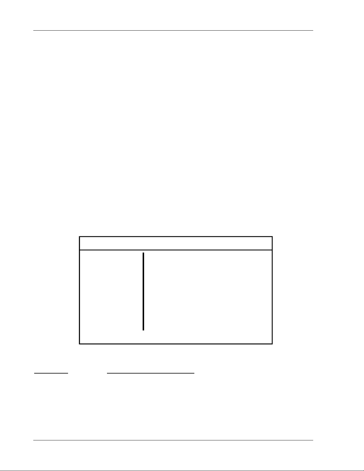
Operation SW 5250A•SW 3500A•SW 1750A
3.3.7.5 CONFIG Sub-Menu
Pressing <Enter> to select CONFIG will display the System Configuration options.
BOOST - Allows the Servo Boost circuit to be disabled during non-sequence operation.
This option is important when running a sequence at low voltage levels. See Section
1.12.2, Servo Boost, for a full explanation of the Boost function. The factory default
state is Boost ON. This option should be set to OFF when:
The RMS Servo is ON (Low Frequency = OFF) and
•
Sequence mode is being used with Exit mode set to “Program Menu.”
•
RESET CAL – Resets calibration constants to default values. Enter a confirmation code
(2096) to activate this option. If you enter an incorrect code, the unit will beep and the
message “! INCORRECT RESET CODE” will be displayed, the code will be reset to 0,
and no changes will occur to the calibration constants.
T&MB OPT – Displays firmware configuration for the Test & Measurement option. ON
indicates the Test & Measurement board is installed; OFF indicates it is not. This field is
for display purposes only.
SWAE OPT – Displays firmware configuration for the Low Impedance option. ON
indicates the Low Impedance hardware is installed; OFF indicates it is not. This field is
for display purposes only.
SYSTEM OUTPUT [OFF]
USER
COMM
EXTERNAL
FAULTS
CONFIG
BOOST ON
RESET CAL 0
T&MB OPT OFF
SWAE OPT OFF
CONFIG Sub-Menu Status and Information Data:
Menu Item
Status and Information Line
BOOST [System boost enable/disable]
RESET CAL [Enter reset code]
T&MB OPT [T&MB board installed?]
SWAE OPT [Low impedance installed?]
3-32 Operation Manual
Page 77

SW 5250A•SW 3500A•SW 1750A Operation
3.4 Front Panel Programming Conventions
• When programming an amplitude in the Program Menu, Sequence Edit Menu,
or remotely over the GPIB, the Amplitude field is checked against the Function
(Waveform) field for positive or negative amplitude; that is, the function polarity is
used to validate the amplitude input value. For example, programming -100V
when a DC+ waveform is selected will result in an execution error.
The polarity check has the following rules:
• Negative amplitudes cannot be input for positive functions.
• Positive amplitudes cannot be input for negative functions.
• If the amplitude of a phase is positive, selecting a negative polarity function
will set the amplitude to zero.
• If the amplitude of a phase is negative, selecting a positive polarity function
will set the amplitude to zero.
• Phases A, B, and C will be of the same frequency. A frequency change of any
phase will affect the output frequency of all phases. The frequency field is
available in all three programming screens as a convenience.
• A sequence can be run on one, two, or all three phases. Two different
sequences cannot be run on two phases simultaneously.
• A sequence setting will take priority over continuous settings.
Operation Manual 3-33
Page 78
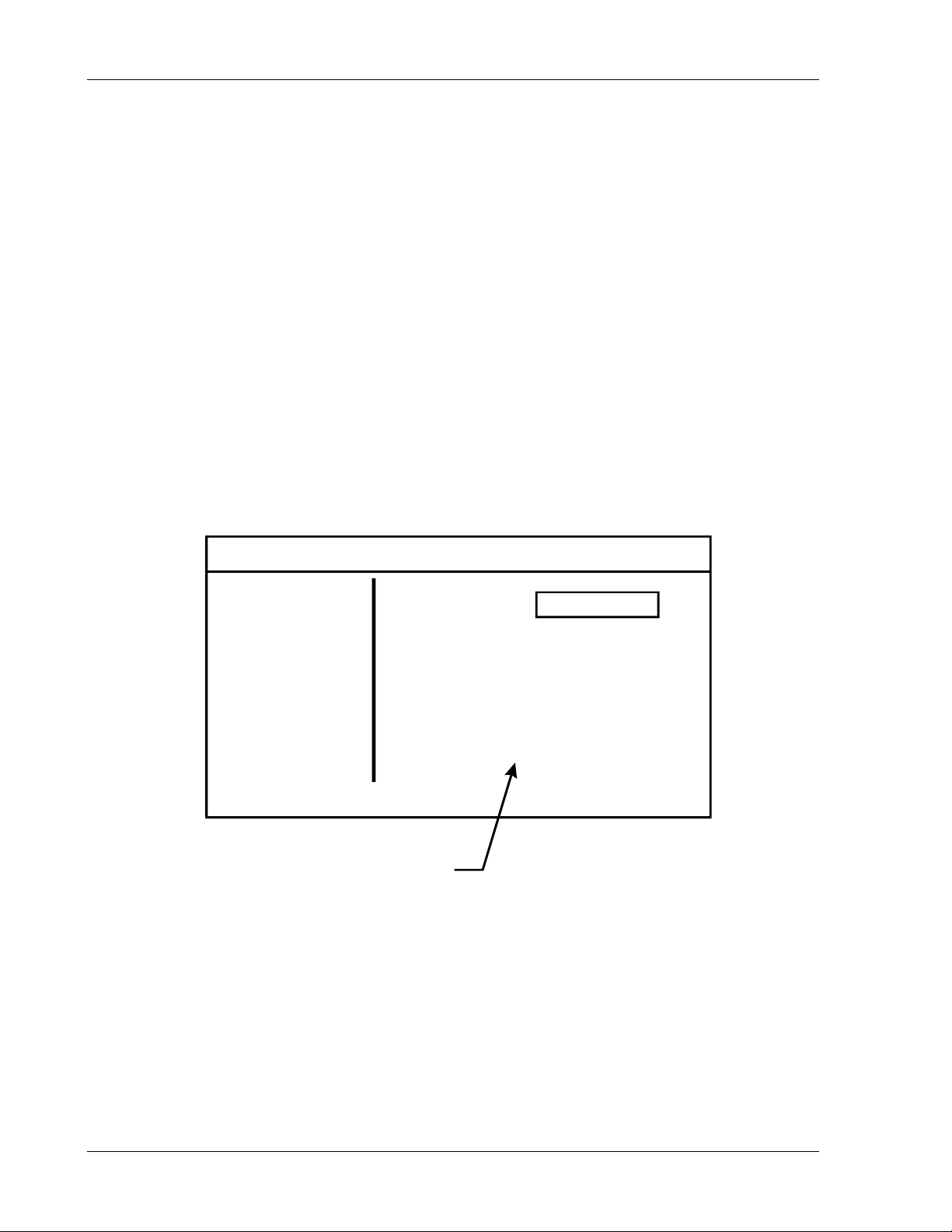
Operation SW 5250A•SW 3500A•SW 1750A
3.5
3.5.1
This example illustrates programming the SW to simulate a current inrush waveform
that is 0V between 0° and 90°, then instantaneously jumps from 0V to 120V at 90°.
1. At the MAIN MENU, use either the Knob or the Up/Down Arrow keys to select the
2. The WAVEFORM Menu will default to the LOAD sub-menu. If the cursor is not
3. Press the Enter key to enter the FUNC (function) mode.
4. Press <Enter> again to place a box around the waveshape selection.
5. Use the Knob to cycle through the waveshape selections until SINE appears in
Front Panel Programming Exercises
Current Inrush Example
WAVEFORM menu, then either press the Enter key or the Right Arrow key.
pointing to LOAD, use the Knob or Up/Down Arrow keys to select LOAD.
the FUNC box.
WAVEFORM OUTPUT [OFF]
LOAD
EDIT
VIEW
SAVE
DELETE
Displays library of waveforms
6. Press <Enter> to load the sine waveshape into scratchpad memory. The
message, [waveform successfully loaded], will indicate that the waveform is now
in scratchpad memory.
7. Press <Menu> to return to the WAVEFORM Menu.
8. Use either the Knob or the Up/Down Arrow keys to select the EDIT sub-menu,
then either press <Enter> or the Right Arrow key. The EDIT menu will be
displayed.
FUNC Sine
3-34 Operation Manual
Page 79
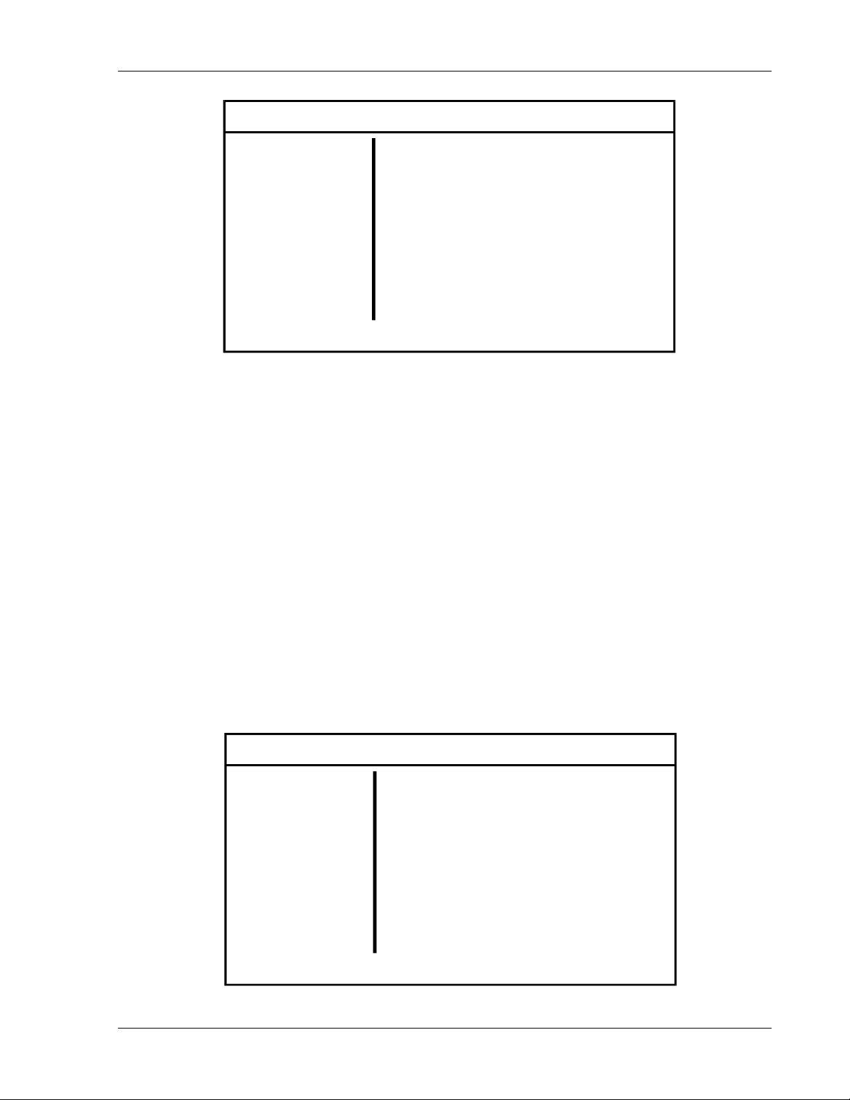
SW 5250A•SW 3500A•SW 1750A Operation
WAVEFORM OUTPUT [OFF]
LOAD
EDIT
VIEW
SAVE
DELETE
9. Use either the Knob or the Up/Down Arrow keys to select FREQ. The frequency
is normally defaulted at 60 Hz with all other values set to 0. On the keypad, enter
6, 0, decimal point, 0, 0, then press <Enter> to set the frequency to 60.00 Hz.
10. Use either the Knob or the Up/Down Arrow keys to select Vrms. Using the
keypad, enter 1, 2, 0, then press <Enter> to set the RMS voltage to 120 volts.
11. Use either the Knob or the Up/Down Arrow keys to select START. Using the
keypad, enter 0, then press <Enter> to set the start phase angle to 0°.
FREQ Hz
Vrms V
START Deg
TIME ms
STOP Deg
AMPL V
60.00
120.00
0.00
4.17
90.00
0.00
12. Although the TIME can be calculated then entered, the STOP function is used in
this example. Select STOP, enter 90 for a 90° phase angle, and press <Enter>.
Note that the unit automatically calculates the TIME (in this case, 4.17 ms).
13. Since the operator is not programming a transient (drop/spike), leave the AMPL
(amplitude) at 0V.
14. Press the Menu key or the Left Arrow key to return to the WAVEFORM Menu.
WAVEFORM OUTPUT [OFF]
LOAD
EDIT
VIEW
SAVE
DELETE
Operation Manual 3-35
Page 80
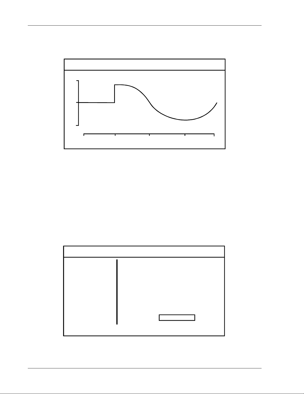
Operation SW 5250A•SW 3500A•SW 1750A
15. Select VIEW, then press <Enter> to view the waveform. A waveform similar to
the one illustrated below should be displayed on the LCD.
WAVEFORM OUTPU T [OFF ]
2
2
1
0
2
2
1
90 180 270
16. To display the waveform on the front panel phase A output:
a. Return to the MAIN MENU by pressing <Menu> twice.
b. Select the PROGRAM Menu, then press <Enter>.
17. In the PHASE A sub-menu:
a. Select FUNC with the Knob, then press <Enter> to place a box around the
waveshape selection.
b. Rotate the Knob until SCRATCH is displayed, then press <Enter>.
MAIN MENU OUTPUT [OFF]
PROGRAM
MEASURE
WAVEFORM
SEQUENCE
INSTR
PHASE A
AMPL 120.00 V
CURL 5.00 A
FREQ 60.00 Hz
θ
ANG 0.00 Deg
SYSTEM
FUNC SCRATCH
3-36 Operation Manual
Page 81

SW 5250A•SW 3500A•SW 1750A Operation
18. While still in the PHASE A sub-menu:
a. Select AMPL (amplitude) with the Knob or Arrow Keys.
b. Enter 120 with the keypad to set the amplitude at 120 volts, then press
<Enter>. The inrush waveform will now be displayed on Phase A output on
the front panel.
19. While still in the PROGRAM mode:
a. Select PHASE B by cursoring to Phase A, then press <Enter>.
b. Select FUNC with the Knob, then press <Enter> to place a box around the
waveshape selection.
c. Rotate the Knob to select TRIANGLE, then press <Enter>.
d. Select AMPL (amplitude) with the Knob, enter 120 with the keypad, then
press <Enter>. A triangular waveform will be displayed on Phase B output
on the front panel.
e. With the field select cursor still at AMPL, press <Enter> to place a box
around the waveshape selection then, using the Knob, vary the amplitude of
the triangular waveform on Phase B.
f. Select PHASE C by cursoring to Phase B, then press <Enter>.
g. Select FUNC with the Knob, then press <Enter> to place a box around the
waveshape selection.
h. Rotate the Knob to select SQUARE, then press <Enter>.
i. Select AMPL (amplitude) with the Knob, enter 120 with the keypad, then
press <Enter>. A square waveform will now be displayed on Phase C
output on the front panel.
j. With the field select cursor still at AMPL, press <Enter> to place a box
around the amplitude selection then, using the Knob, vary the amplitude of
the square waveform on Phase C.
20. Press <Menu> or the Left Arrow key to return to the MAIN MENU.
Operation Manual 3-37
Page 82
Operation SW 5250A•SW 3500A•SW 1750A
3.5.2 Voltage Spike Example
This example illustrates programming the SW for a voltage spike on a 150V sine
waveform that starts at 30° and ends at 50° with an amplitude of 220.6 volts.
MAIN MENU OUTPUT [OFF]
PROGRAM
MEASURE
WAVEFORM
SEQUENCE
INSTR
SYSTEM
1. At the MAIN MENU, select the WAVEFORM menu, then press <Enter>.
WAVEFORM OUTPUT [OFF]
LOAD
EDIT
VIEW
SAVE
DELETE
2. The WAVEFORM Menu will default to the LOAD sub-menu. If the cursor is not
pointing to LOAD, use the Knob or Up/Down Arrow keys to select LOAD.
3. Press the Enter key to enter the FUNC (function) mode.
4. Press <Enter> again to place a box around the waveshape selection.
5. Use the Knob to cycle through the waveshape selections until SINE appears in
the FUNC box.
3-38 Operation Manual
Page 83
SW 5250A•SW 3500A•SW 1750A Operation
WAVEFORM OUTPUT [OFF]
LOAD
EDIT
VIEW
SAVE
DELETE
Displays library of waveforms
6. Press <Enter> to load the sine waveshape into scratchpad memory. The
message, [waveform successfully loaded], will indicate that the waveform is now
in scratchpad memory.
7. Press <Menu> to return to the WAVEFORM Menu.
8. Use either the Knob or the Up/Down Arrow keys to select the EDIT sub-menu,
then either press <Enter> or the Right Arrow key. The EDIT menu will be
displayed.
FUNC Sine
WAVEFORM OUTPUT [OFF]
LOAD
EDIT
VIEW
SAVE
DELETE
9. Select Vrms. Enter 150 using the keypad, then press <Enter> to set the RMS
voltage to 150 volts.
Operation Manual 3-39
FREQ Hz
Vrms V
START Deg
TIME ms
STOP Deg
AMPL V
60.00
120.00
30.00
0.93
50.00
220.60
Page 84
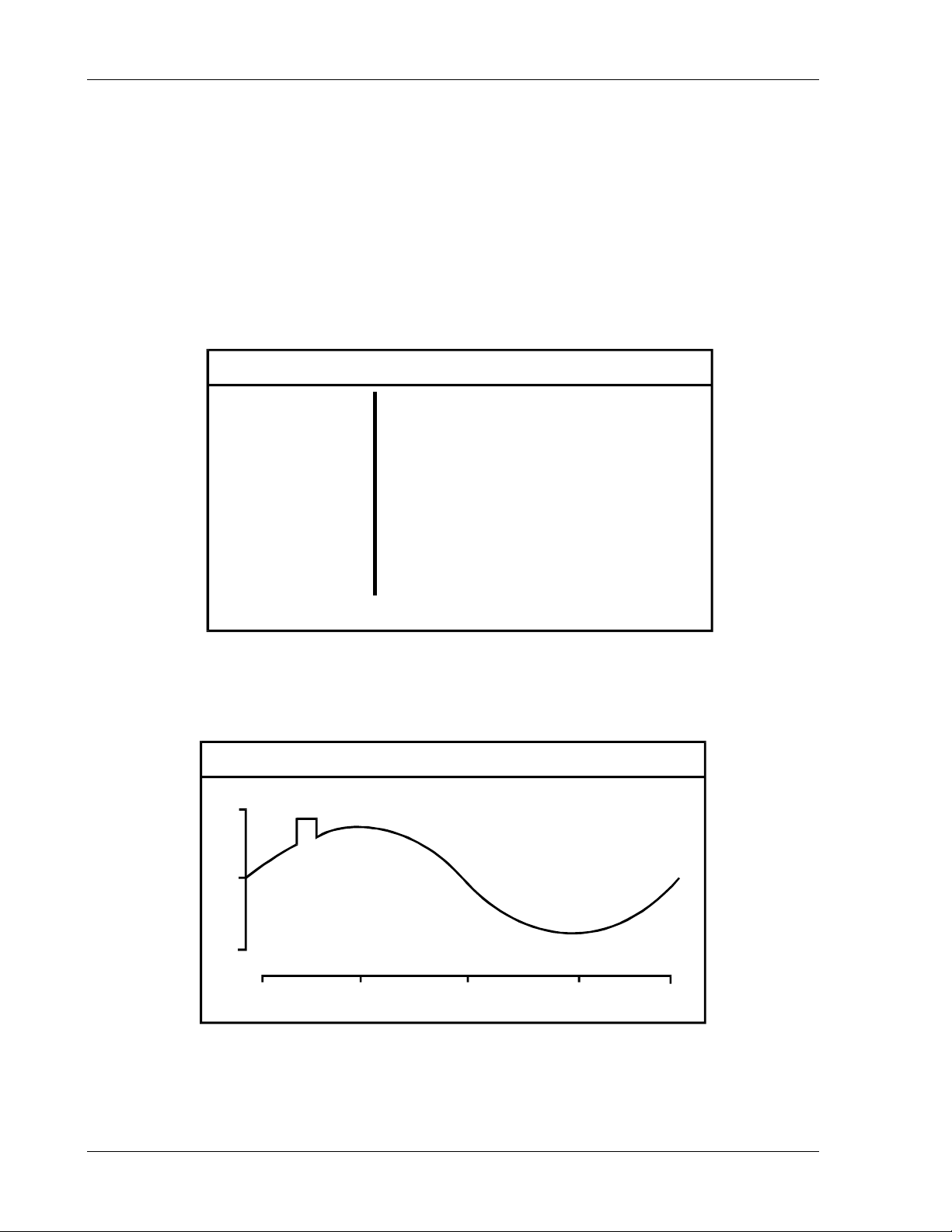
Operation SW 5250A•SW 3500A•SW 1750A
10. Select START. Enter 30 using the keypad, then press <Enter> to set the
starting phase angle to 30°.
11. Select STOP. Enter 50 using the keypad for an ending phase angle of 50°, then
press <Enter>. Note that the instrument automatically calculates the TIME (in
this case, 0.93 ms).
12. Select AMPL. Enter 220.6, then press <Enter> to set the amplitude to 220.6V.
13. Press <Menu> to return to the WAVEFORM Menu.
WAVEFORM OUTPUT [OFF]
LOAD
EDIT
VIEW
SAVE
DELETE
14. Select VIEW to view the scratchpad, then press <Enter>. A waveshape similar
to the one illustrated below should be displayed on the scratchpad.
WAVEFORM OUTPU T [OFF ]
2
2
1
0
2
2
1
90 180 270
3-40 Operation Manual
Page 85
SW 5250A•SW 3500A•SW 1750A Operation
15. To retain the waveshape and display it on Phase A output on the front panel:
a. Return to the MAIN MENU by pressing <Menu> twice.
b. Select the PROGRAM Menu, then press <Enter>.
MAIN MENU OUTPUT [OFF]
PROGRAM
MEASURE
WAVEFORM
SEQUENCE
INSTR
SYSTEM
16. In the PHASE A sub-menu:
a. Select FUNC with the Knob, then press <Enter> to place a box around the
waveshape selection.
b. Rotate the Knob until SCRATCH is displayed, then press <Enter>. The
scratchpad waveform will now be displayed on Phase A of the oscilloscope.
17. Press <Menu> or the Left Arrow key to return to the MAIN MENU.
PHASE A
AMPL 120.00 V
CURL 5.00 A
FREQ 60.00 Hz
θ
ANG 0.00 Deg
FUNC SCRATCH
Operation Manual 3-41
Page 86
Operation SW 5250A•SW 3500A•SW 1750A
3.5.3 Voltage Dropout Example
This example illustrates programming the SW for a voltage dropout on a 120V sine
waveform that starts at 45° with a duration of 1 millisecond and an amplitude of 10 volts.
MAIN MENU OUTPUT [OFF]
PROGRAM
MEASURE
WAVEFORM
SEQUENCE
INSTR
SYSTEM
1. At the MAIN MENU, select the WAVEFORM menu, then press <Enter>.
WAVEFORM OUTPUT [OFF]
LOAD
EDIT
VIEW
SAVE
DELETE
2. The WAVEFORM Menu will default to the LOAD sub-menu. If the cursor is not
pointing to LOAD, use the Knob or Up/Down Arrow keys to select LOAD.
3. Press the Enter key to enter the FUNC (function) mode.
4. Press <Enter> again to place a box around the waveshape selection.
5. Use the Knob to cycle through the waveshape selections until SINE appears in
the FUNC box.
3-42 Operation Manual
Page 87
SW 5250A•SW 3500A•SW 1750A Operation
WAVEFORM OUTPUT [OFF]
LOAD
EDIT
VIEW
SAVE
DELETE
Displays library of waveforms
6. Press <Enter> to load the sine waveshape into scratchpad memory. The
message, [waveform successfully loaded], will indicate that the waveform is now
in scratchpad memory.
7. Press <Menu> to return to the WAVEFORM Menu.
8. Use either the Knob or the Up/Down Arrow keys to select the EDIT sub-menu,
then either press <Enter> or the Right Arrow key. The EDIT menu will be
displayed.
FUNC Sine
WAVEFORM OUTPUT [OFF]
LOAD
EDIT
VIEW
SAVE
DELETE
9. Select Vrms. Enter 120, then press <Enter> to set the RMS voltage to 120
volts.
Operation Manual 3-43
FREQ Hz
Vrms V
START Deg
TIME ms
STOP Deg
AMPL V
60.00
120.00
45.00
1.00
66.60
10.00
Page 88
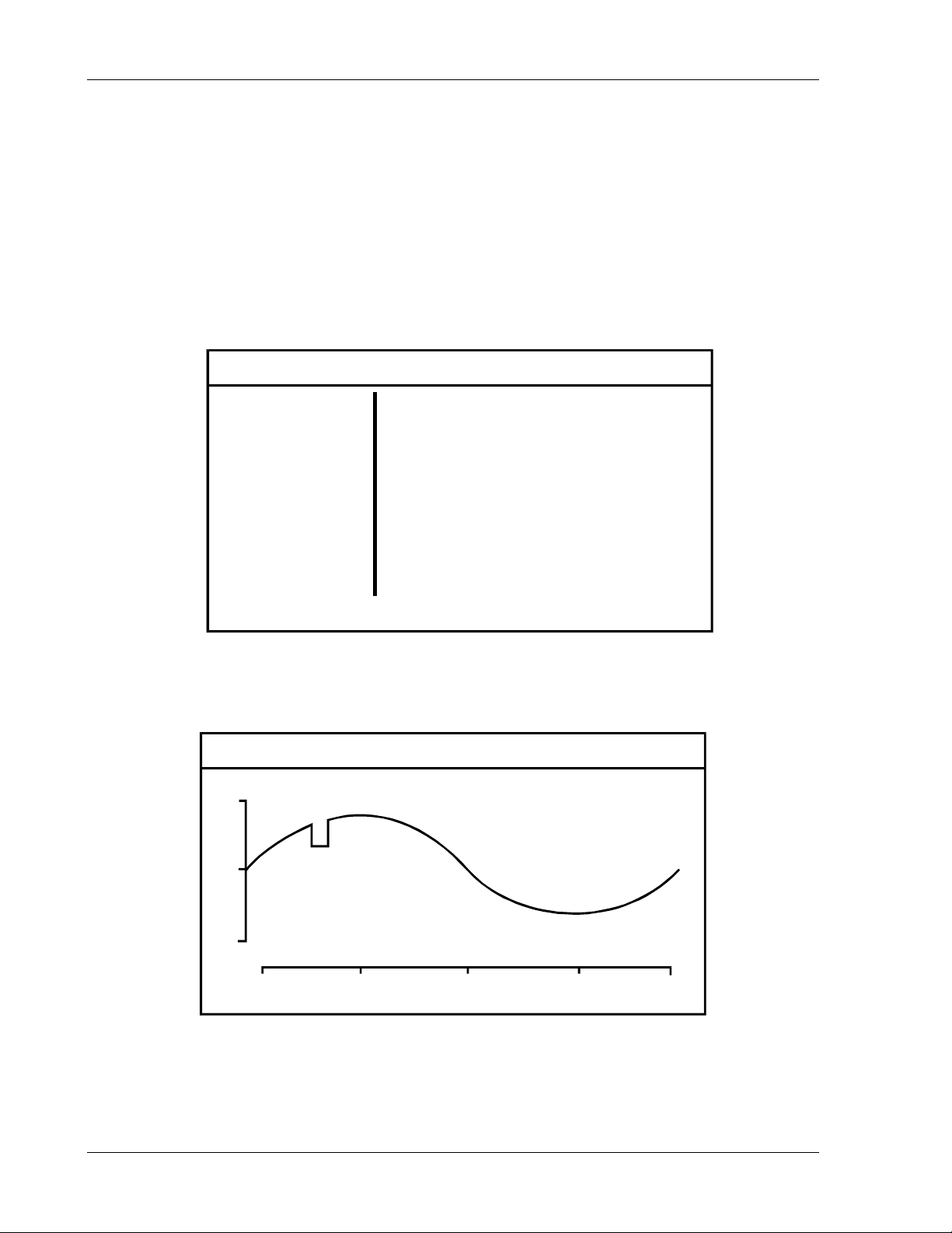
Operation SW 5250A•SW 3500A•SW 1750A
10. Select START. Using the keypad, enter 45, then press <Enter> to set the
starting phase angle to 45°.
11. Select TIME, enter 1 for a duration of 1 millisecond, then press <Enter>. Note
that the instrument automatically calculates the STOP phase angle value (in this
case, 66.6°).
12. Select AMPL, enter 10 for 10 volts, then press <Enter>.
13. Press <Menu> to return to the WAVEFORM Menu.
WAVEFORM OUTPUT [OFF]
LOAD
EDIT
VIEW
SAVE
DELETE
14. Select VIEW to view the scratchpad, then press <Enter>. A waveshape similar
to the one illustrated below should be displayed on the scratchpad.
WAVEFORM OUTPU T [OFF ]
2
2
1
0
2
2
1
90 180 270
3-44 Operation Manual
Page 89
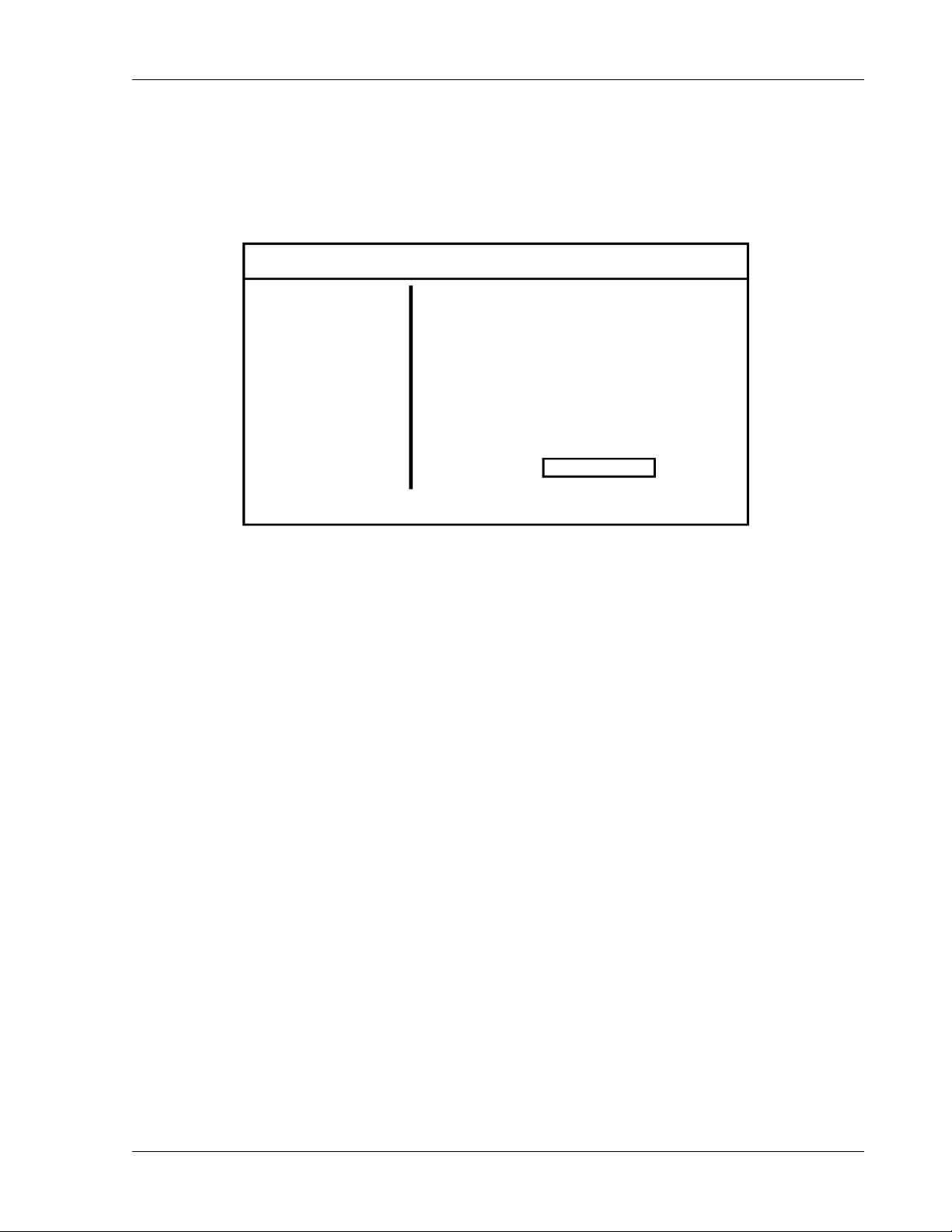
SW 5250A•SW 3500A•SW 1750A Operation
15. To retain the waveshape and display it on Phase A of the oscilloscope:
a. Return to the MAIN MENU by pressing <Menu> twice.
b. Select the PROGRAM Menu, then press <Enter>.
MAIN MENU OUTPUT [OFF]
PROGRAM
MEASURE
WAVEFORM
SEQUENCE
INSTR
SYSTEM
16. In the PHASE A sub-menu:
a. Select FUNC with the Knob, then press <Enter> to place a box around the
waveshape selection.
b. Rotate the Knob until SCRATCH is displayed, then press <Enter>. The
scratchpad waveform will now be displayed on Phase A of the oscilloscope.
17. Press <Menu> or the Left Arrow key to return to the MAIN MENU.
PHASE A
AMPL 120.00 V
CURL 5.00 A
FREQ 60.00 Hz
θ
ANG 0.00 Deg
FUNC SCRATCH
3.6 SCPI Specification
Refer to the SmartWave™ Switching Amplifier SCPI Programming Manual
(Elgar Document No. M162000-03).
Operation Manual 3-45
Page 90

Page 91
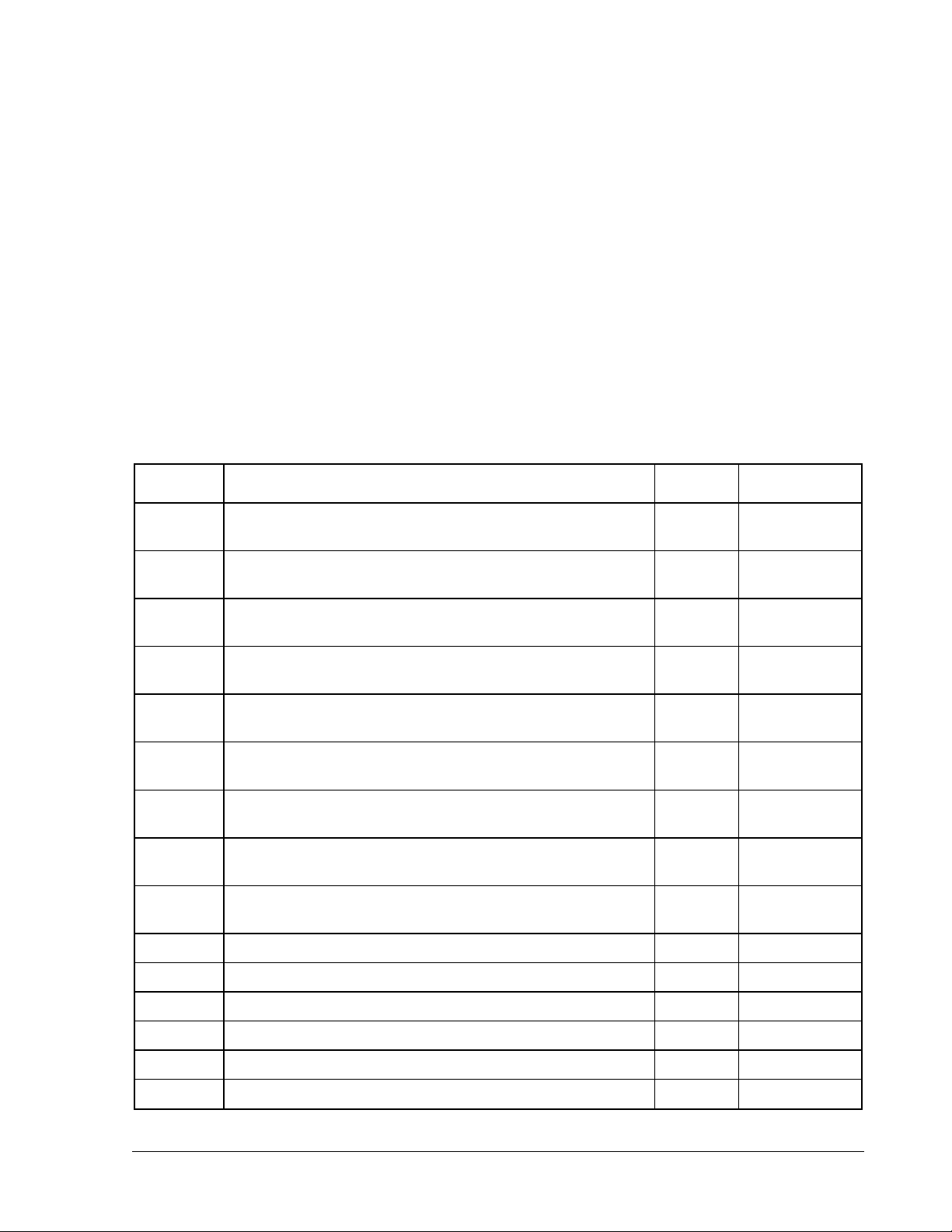
STANDARD WAVEFORMS
The following standard waveforms are provided in the SW Series:
NAME DESCRIPTION
Clip0 A sine wave with the positive halfcycle clipped at 0V from
50 to 130°
ClipPos A sine wave with the positive halfcycle clipped from
50 to 130°
ClipNeg A sine wave with the positive halfcycle set to a 50%
negative value from 50 to 130°
DC+ Used to operate the SW as a positive DC source
(true rms)
SCALE
FACTOR
SECTION 4
FREQUENCY
RANGE
1.0 40-5000 Hz
1.0 40-5000 Hz
1.0 40-5000 Hz
0.7071 N/A
DC- Used to operate the SW as a negative DC source
(true rms)
DcRip03+ +DC with 3% ripple. Frequency of the ripple is deter-
mined by the programmed output frequency (true rms)
DcRip03- -DC with 3% ripple. Frequency of the ripple is determined
by the programmed output frequency (true rms)
DcRip10+ +DC with 10% ripple. Frequency of the ripple is deter-
mined by the programmed output frequency (true rms)
DcRip10- -DC with 10% ripple. Frequency of the ripple is deter-
mined by the programmed output frequency (true rms)
Drop45 Sine with a drop-out above 0V from 45 to 60° 1.0 40-5000 Hz
DropNeg Sine with a drop-out to -Vpeak from 4 to 50° 1.0 40-5000 Hz
DropPeak Sine wave with drop-out to 0V from 8 to 110° 1.0 40-5000 Hz
ExtrnDir DC for use with System External direct input 1.0 40-5000 Hz
FlatTp05 Flat-top sine wave with 5% distortion (true rms) 0.9344 40-5000 Hz
FlatTp10 Flat-top sine wave with 10% distortion (true rms) 0.8894 40-5000 Hz
0.7071 N/A
0.7071 40-5000 Hz
0.7071 40-5000 Hz
0.7071 40-5000 Hz
0.7071 40-5000 Hz
Operation Manual 4-1
Page 92
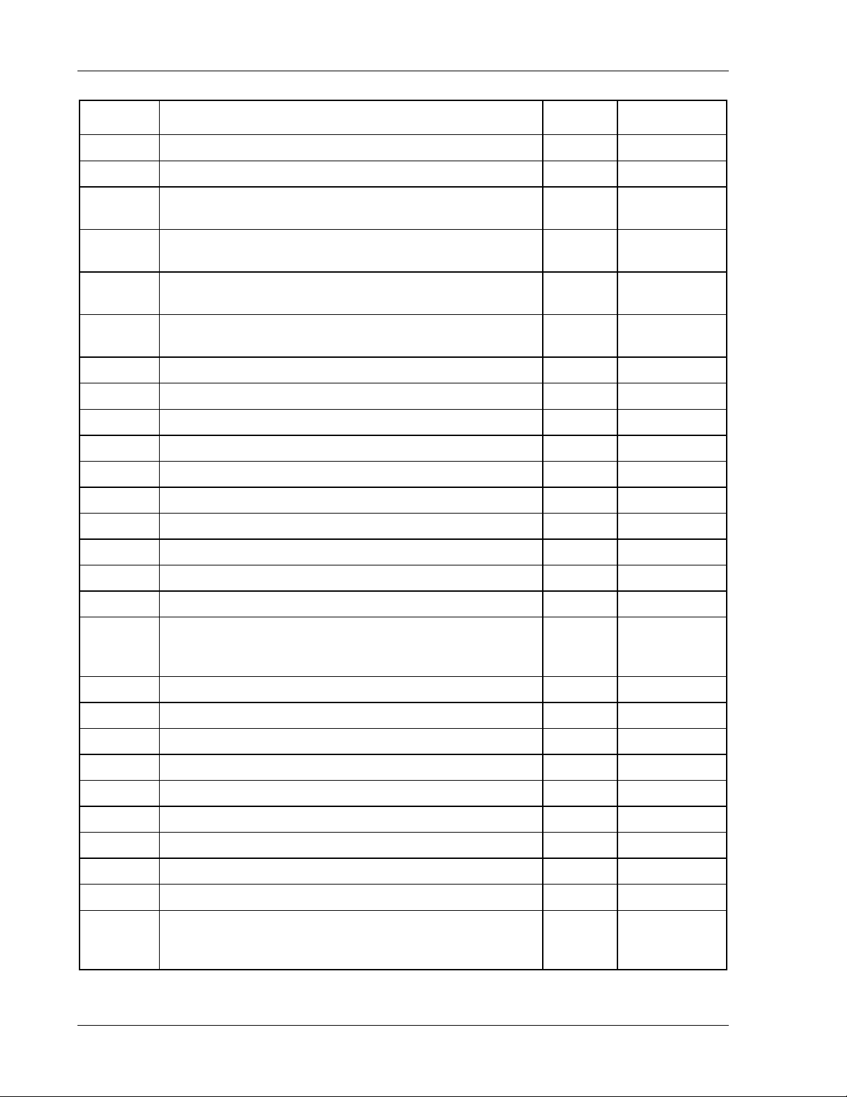
Standard Waveforms SW 5250A•SW 3500A•SW 1750A
NAME DESCRIPTION
FlatTp15 Flat-top sine wave with 15% distortion (true rms) 0.8545 40-5000 Hz
FlatTp20 Flat-top sine wave with 20% distortion (true rms) 0.8251 40-5000 Hz
Four3 Fourier square wave with 1st and 3rd harmonics
(true rms)
Four5 Fourier square wave with 1st, 3rd, and 5th harmonics
(true rms)
Four7 Fourier square wave with 1st, 3rd, 5th, and 7th harmonics
(true rms)
Four9 Fourier square wave with 1st, 3rd, 5th, 7th, and 9th
harmonics (true rms)
FulRect+ Positive DC full rectified sine wave 1.0 40-5000 Hz
FulRect- Negative DC full rectified sine wave 1.0 40-5000 Hz
HalfCyc Sine wave with 90 to 180° at 0Volts 1.0 40-5000 Hz
HlfRect+ Positive DC half rectified sine wave 1.0 40-5000 Hz
HlfRect- Negative DC half rectified sine wave 1.0 40-5000 Hz
Inrush Sine wave with first quarter (0 to 90°) at 0Volts 1.0 40-5000 Hz
SCALE
FACTOR
0.8946 40-5000 Hz
0.8703 40-5000 Hz
0.8595 40-5000 Hz
0.8537 40-5000 Hz
FREQUENCY
RANGE
Noisz010 Sine with 10% noise at zero crossings (true rms) 1.0 40-5000 Hz
Noisz100 Sine with 100% noise at zero crossings (true rms) 1.0 40-5000 Hz
Pcntl110 Phase control at 110° 1.0 40-5000 Hz
Pcntl170 Phase control at 170° 1.0 40-5000 Hz
Scratch Waveform scratchpad. This is the waveform edit work
area. Waveforms being edited can be output for testing
purposes before they are saved to non-volatile memory.
SinDc01+ Sine wave with +1% DC offset 1.0 40-5000 Hz
SinDc01- Sine wave with - 1% DC offset 1.0 40-5000 Hz
SinDc10+ Sine wave with +10% DC offset 1.0 40-5000 Hz
SinDc10- Sine wave with - 10% DC offset 1.0 40-5000 Hz
SinDc20+ Sine wave with +20% DC offset 1.0 40-5000 Hz
SinDc20- Sine wave with - 20% DC offset 1.0 40-5000 Hz
SinDc50+ Sine wave with +50% DC offset 1.0 40-5000 Hz
SinDc50- Sine wave with - 50% DC offset 1.0 40-5000 Hz
Sine Sine wave (true rms) 1.0 40-5000 Hz
Spike200 Sine with spikes at peaks. Spikes are from 85 to 95°
and calibrated to be 200Vpeak when programmed to
120Vrms
1.0 Maximum of
waveform
loaded
1.1785 40-5000 Hz
4-2 Operation Manual
Page 93
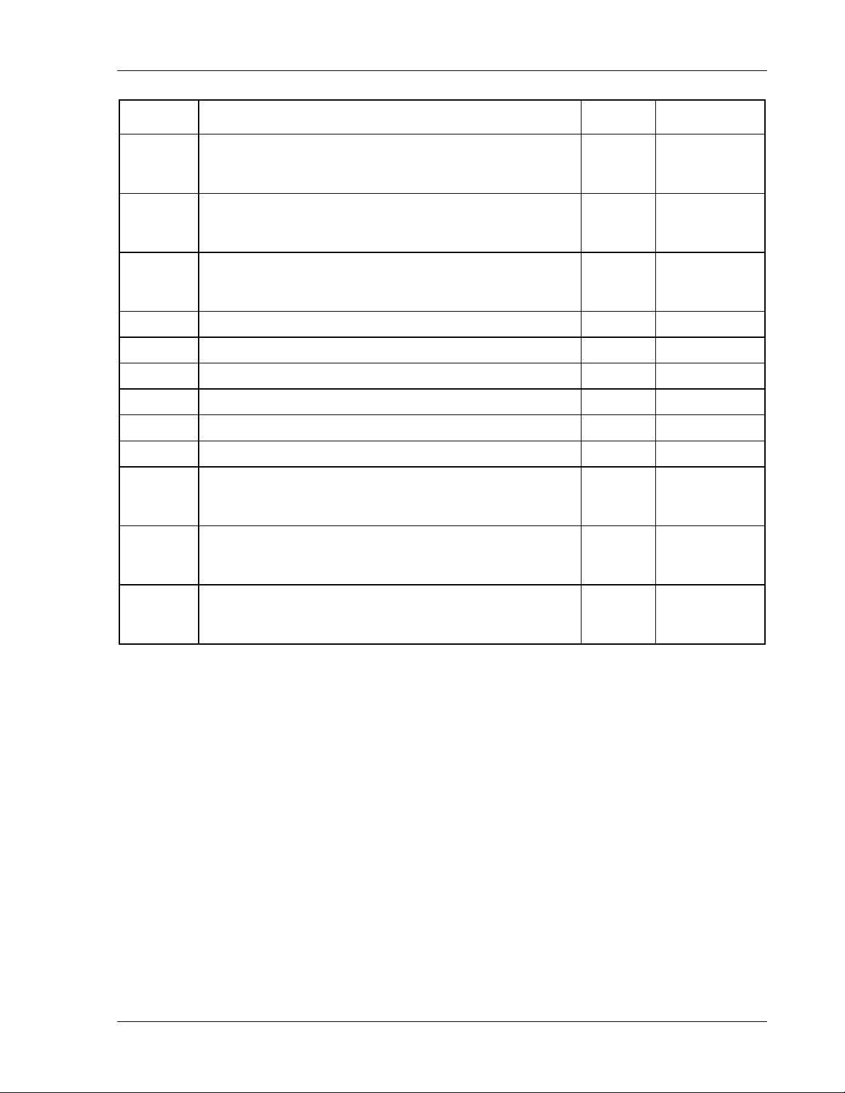
SW 5250A•SW 3500A•SW 1750A Standard Waveforms
NAME DESCRIPTION
Spike250 Sine with spikes at peaks. Spikes are from 85 to 95°
and calibrated to be 250Vpeak when programmed to
120Vrms
Spike300 Sine with spikes at peaks. Spikes are from 85 to 95°
and calibrated to be 300Vpeak when programmed to
120Vrms
Spike400 Sine with spikes at peaks. Spikes are from 85 to 95°
and calibrated to be 400Vpeak when programmed to
120Vrms
Square Square wave with 50% duty cycle (true rms) 0.7071 40-5000 Hz
Step_06 Six voltage step sine wave 1.0 40-5000 Hz
Step_12 Twelve voltage step sine wave 1.0 40-5000 Hz
Step_24 Twenty-four voltage step sine wave 1.0 40-5000 Hz
Taylor 5th harmonic Taylor series wave (true rms) 0.9136 40-5000 Hz
Triangle Triangle wave (true rms) 1.2246 40-5000 Hz
Z1 3-phase output with a voltage spike occurring at the same
point in time. Spikes are from 45 to 90° and calibrated to
be 200 Vpeak when programmed to 80 Vrms
SCALE
FACTOR
1.4731 40-5000 Hz
1.7678 40-5000 Hz
2.3570 40-5000 Hz
1.0 40-5000 Hz
FREQUENCY
RANGE
Z2 3-phase output with a voltage spike occurring at the same
point in time. Spikes are from 165 to 210° and calibrated
to be 200 Vpeak when programmed to 80 Vrms
Z3 3-phase output with a voltage spike occurring at the same
point in time. Spikes are from 285 to 330° and calibrated
to be 200 Vpeak when programmed to 80 Vrms
1.0 40-5000 Hz
1.0 40-5000 Hz
Operation Manual 4-3
Page 94

Standard Waveforms SW 5250A•SW 3500A•SW 1750A
This page intentionally left blank.
4-4 Operation Manual
 Loading...