

Page 1
The
Z-Box Sm
artH
om
e
C
ontroller
Version2/Z-Wave Cert No:ZC10-
XXXXXXXX
Quick Start
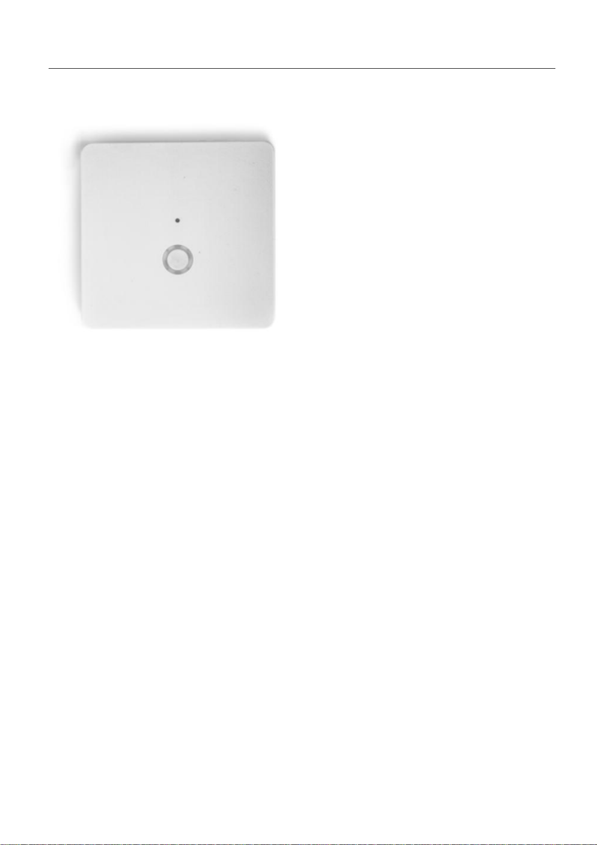
This device is a control center (gateway) for Z-Wave home automation networks. It is used to control different
single devices as well as complete defined scenes and actions combining device functions within the network.
It needs only a few steps to get your Z-box up and running.
1. Power it up by plugging in the external power supply
2. Connect the z-box to your local router using a standard Ethernet cable
3. Use a web browser on your desktop PC or mobile internet device and go to login page .Input the IP
address into the address bar, press ENTER to enter the login page.(IP address:192.168.10.1)
4. Login using the initial local default login (login: admin; password: 123456)
5. Got to setup (upper right corner)
password. This password is used for accessing the controller from outside the home. It is shared among all
local users in the home. If you want to protect your login from other users inside the home, change t he local
default password.
6. Define your rooms using
7. Setup the other users and give them access to the rooms.
8. Installing your smart home devices one by one. Use the dialog
Rooms
My Settings
, remember your remote access ID and define your remote
Devices
for this
Hardware
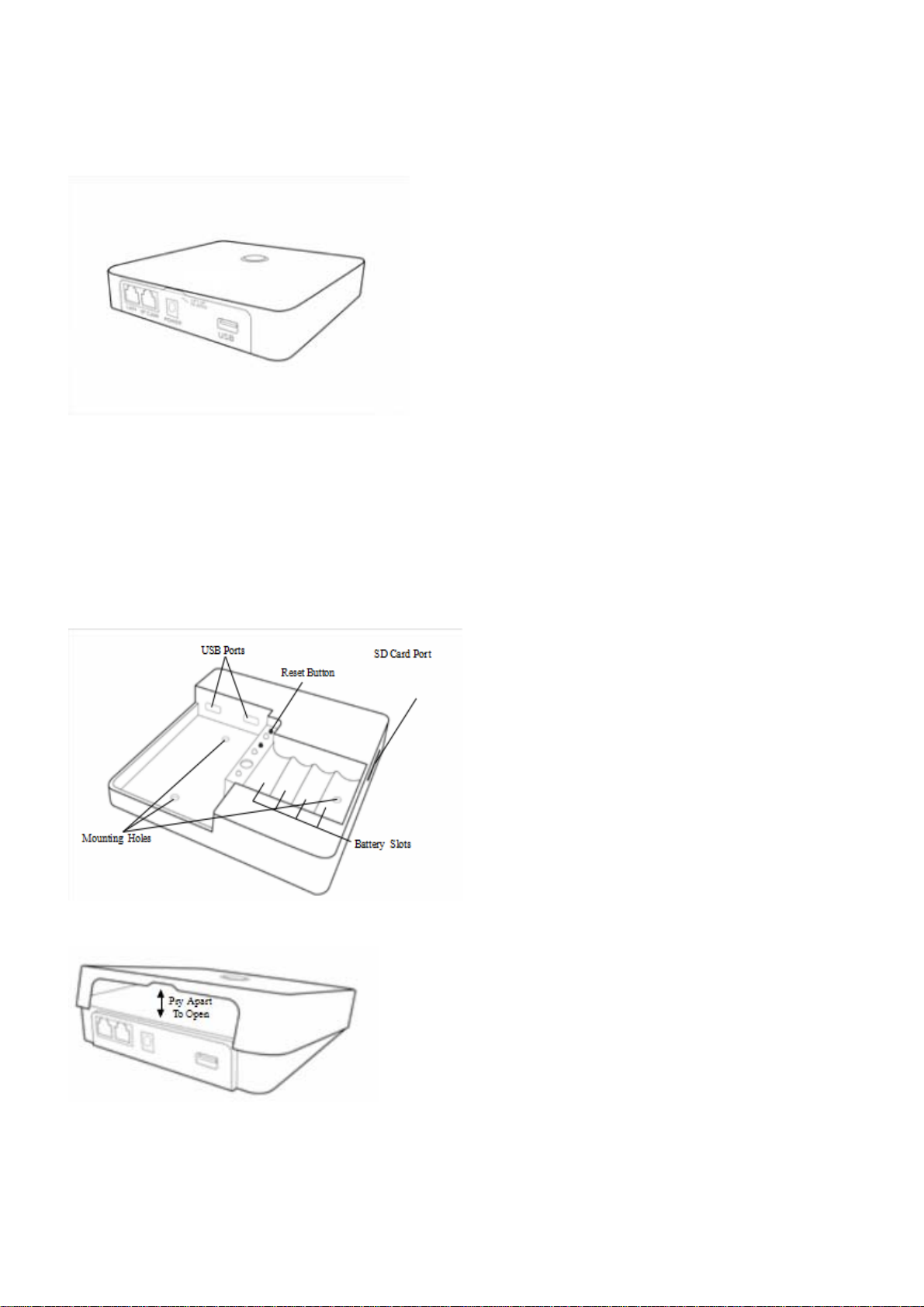
The Z-Box is a small but powerful hardware offering various interfaces:
• Power Input: The device is powered by AC adapter DC9V 1.3A.
• Ethernet: The device can be connected to any standard 10/100 MBit/s Ethernet router
• 3*USB(2insidethechamberand1external):The3USBportsallowtoconnectadditionalcommunication
or storage options such as an EnOcean dongle, Bluetooth dongle, hard disk or any other USB device suitable
for Z-box.
Installation
• Connect to Router
Using the LAN cable connect the Z-box to your router.
1
Page 2
Note-If a connection through the router is not available, there is an refer to the Dome App for step-by-step
instructions when installation is complete.
• Connect to Power
Using the cord provided, connect the Z-box to an electrical wall outlet.
Installing Batteries (optional)
The Z-box uses 4 Ni-MH AA Rechargeable batteries (not included) which allow the system to continue
operation for up to 6 hours (depend on battery capacity and application) when the power is out.
We recom mend use 2400mA
Z-Box provide trickle charge to recharge battery which is the safe st charging technique, it takes approx. 48
hours to fully recharge 4 x 2400mA Ni-MH rechargeable batteries – please DON’T MIX different
capacity/brand/age of batteries.
To install the batteries, pry open the lid of the Z-box at the notch in the back just above the cable ports.
LED Behavior
2
Page 3
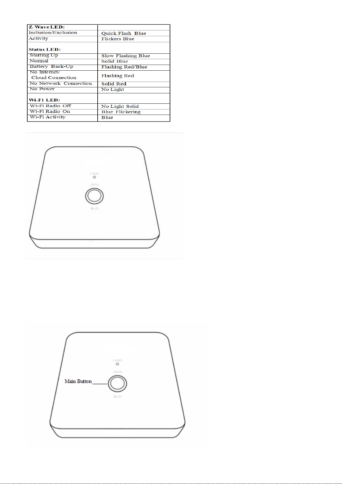
Defaulting Network Settings
To reset the Network to the default settings, press and hold the Main button (on top of the Z-box) for 10
seconds. Release the button when the LED quickly flashes red indicating reset. Refer to the Dome App to
reconnect the Z-box.
3
Page 4
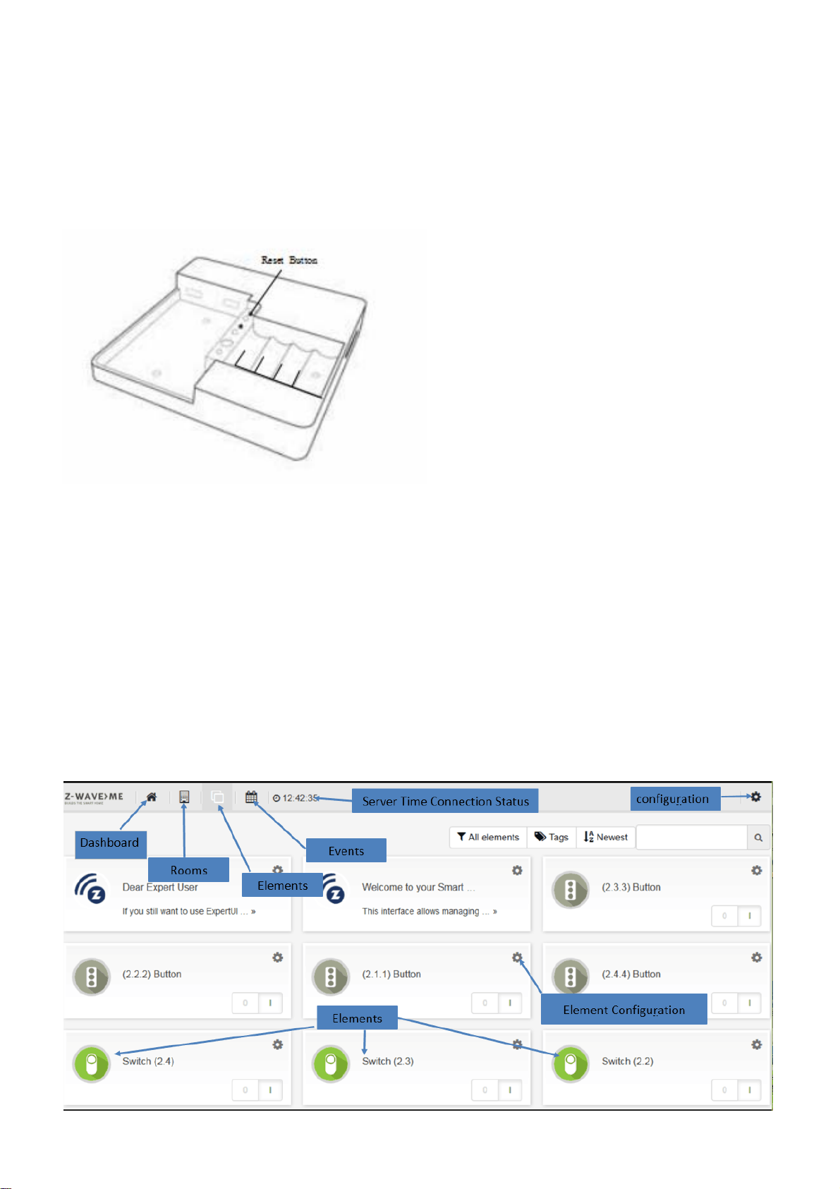
Defaulting the Z-box to Factory Settings
Important:
presets.
To revert to the Factory default settings, press and hold the Reset button (inside the Z-box) for 10 seconds.
Release the button when the Status LED quickly flashes red indicating reset.
Resetting the Z-box will delete all the settings, disconnect all Z-Wave devices and delete all of the
Smart Home User Interface
Your smart home can be controlled from different user interface. The design of the interface will adapt to the
various screens of PC, pads or mobile phones.
This interface allows managing your smart home equipped with interconnected Z-Wave devices. It will show
every function of the device as one single Element (In case a physical device has multiple functions – like
switching and metering – it will generate multiple elements). All elem ents are listed in the Element View and
can be filtered by function type (switch, dimmer, sensor) or other filtering criteria. Important elements can be
placed in the Dashboard. Additionally the elements can be grouped into rooms. Every change of a sensor value
or a switching status is called an event and is shown in the Timeline. Filtering allows monitoring the changes
of one single function or device.
4
Page 5

Functions of the User Interface
General
Thegreentimeontheheadershowsthetimeofthelastcommunicationtothesmarthomegateway.Incase
communication gets lost, a red sign is shown.
Different users (login/password) have different dashboards and settings. Apps and tags are activated for all
users. Admin privilege is to setup new users, install/configure/delete apps and assigning access rights of
rooms to users
Elements
Clicking into the element may show more control options (like for dimmers or motor control). Switching a
switch will immediately result in showing the new state but in greyed. Once the wireless network reconfirms
the n ew state of the switch, the new switching status is shown using the real color icon.
The Element Configuration allows assigning user-defined tags to differen t elements. This allows further
grouping or filtering. It is even possible to use tags inside apps to auto-select certain elements. The time
shown in certain elements refers to the time where value was read from the sensor. You can change this by
configuring the app “Sensor Polling”.
Some physica l Z-Wave devices are quite complex generating a lot of functions. You may want to delete
certain elements from the element view. This can be done on the elements configuration with the checkbox
“Permanently delete”. If you accidently deleted an element you need to go to Setup Z-Wave Network, Tab
Network and click on the physical device that generated the very element. Here you can hide/unhide every
element.
Timeline
Some elements may create a lot of events regardless of their possible pollin g. If you don’t want them to
flood you r timeline disable all events from this device using the element‘s configuration dialog. In your
personal settings you can define if new elements shall generate events or not. This setting can be changed
as well.
Devices
You can include all certified Z-Wave devices. If you can’t find y our device in the list of known devices please
use the Autodetect function. It will create the same result but you need to find out from the device manual
how to add (include) the device to the network.
To use EnOcean devices a specia l EnOcean transmitter USB stick needs to be attached to the Z-box.
Furthermore the EnOcean module needs to be activated. Please note that only a selection of EnOcean
devices are supported by the EnOcean module. You can browse through the list of supported EnOcean
devices.
5
Page 6

Z-Wave Network
This menu option allows a deeper look into the Z-Wave network. The tab
devices and the elements controlled by them. A configuration button allows changing the names and room
assignment of all element. At the end of this dialog a button
specific configuration dialog. Some Z-Wave devices offer such configurations to adapt their functions. Not
having this configuration option is n ot a malfunction!
The tab
the Z- Way Expert User Interface. Please note that this Expert User Interface is for Z-Wave experts. The
Razberry documentation and user forums will provide help for its use if needed. Direct access to the ZWave Expert User Interface is always possible using http:/ /ip:8083/expert/
Network Status
lists possible problems of Z-Wave devices and the Z-Wave network. A link refers to
Hardware Configuration
Network
lists all Z-Wave hardware
leads to a hardware
My Settings
This menu allows the usual user settings (color, languages, preferences). For users with admin privileges
this dialog also controls the essential access credentials for the remote access using find.z-wave.me.
User Management
This menu item is only available for users with admin privileges.
The Z-Box Z-box is powered by Z-Way, the famous Z-Wave control software of Z-Wave.Me that is also
powering famous projects such as Razberry (razber r y .zwave.me: This means that all apps, workar ounds,
tricks and How Tos provided and describes for the Razberry project – e.g. on http://forum.z-wave.me/ –
can be used and applied for the Z-box too.
Super
Quick
Z-Box
installation andusagewithoutinstallingfurthersoftware
apps
that
Quick
1. 2. Go tofind.zwave.me,find
3.
Setup
4.
Choose
Hom
e
Interface.
Start
is a
forvariou
further
Start
your
password
http://YOURPI_IP:
for
Z-Wavecontroller
smobileplatforms
enhance the userexperience
for Insid
the
and
rest
remember
8083 or
of
ers
theIPaddress
your Z-BoxIDforfuture
usefind.zwave.me
us
for your Smart
that
canbe
of thesolutio
of your Z-Box, clic k onit
Home.
downloaded
Abuilt-in
n.
remoteaccess
for
remote acce ss
or
apps.
from
thevarious
to your Smart
web server
Of
course there are
allows fast
app stores
6
Page 7
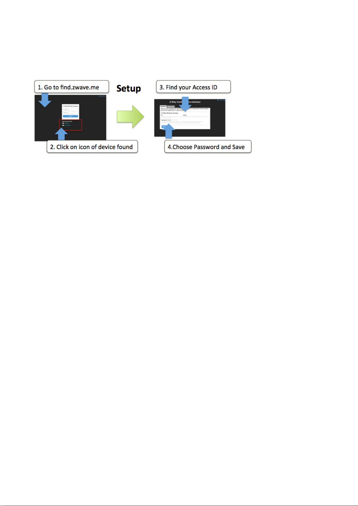
Poweritup. After about1minute
openawebbrowserand pointtofind.zwave.m
e
Below
address
the
login
link toopen
screen
you will
theconfigurationdialog.
The Configuration Service
The
configurationserviceisaccessible
want to
of
changesettingsthisservice
the Z-Waveengine
.
see theIPaddress
with any
will
be
at yourservice
of your
web browser
Z-Box syst e m.
andisavailableindependent
on Port
Click on
8084. Whenever
the
IP
you
Find your Z-BoxIDand rememb er
1.
Chooseapassword tha t
future.Wheneveryo
will not
TheConfigurationserviceuses
f
uncti
ons
Fi
nd theIPAddress of your
RemoteAccess
seeabove.
FirmwareUpdate:Just
RemoteSuppor
if youdesire
under
Once
you
needapassword
:
when
remoteservice.Allowing servicepeopletoaccess
yourcontrol
set
your
remote access password
t:Thisfunctionis usuallydisabled.You
uaccess
you
click on
.
.
thecl
Z-Box.
areoutsideyour
it for
remote access
will
be used
your
oudinfrastructureonfind.zwave.mefor thefollowing
You just
the firmware
toaut
Z-Box
you
within your local
used
home.
update tab and
are done
to yoursystem
henticatefor the
network(as
thisfunction
For this avalid
with
.
will
needtoenableit on
the
.
remote accessinthe
the
passwordisrequired–
follow
theinstructions
your
Z-Box
initialconfiguratio
firsttime)you
request
is 100%
n.
7
Page 8
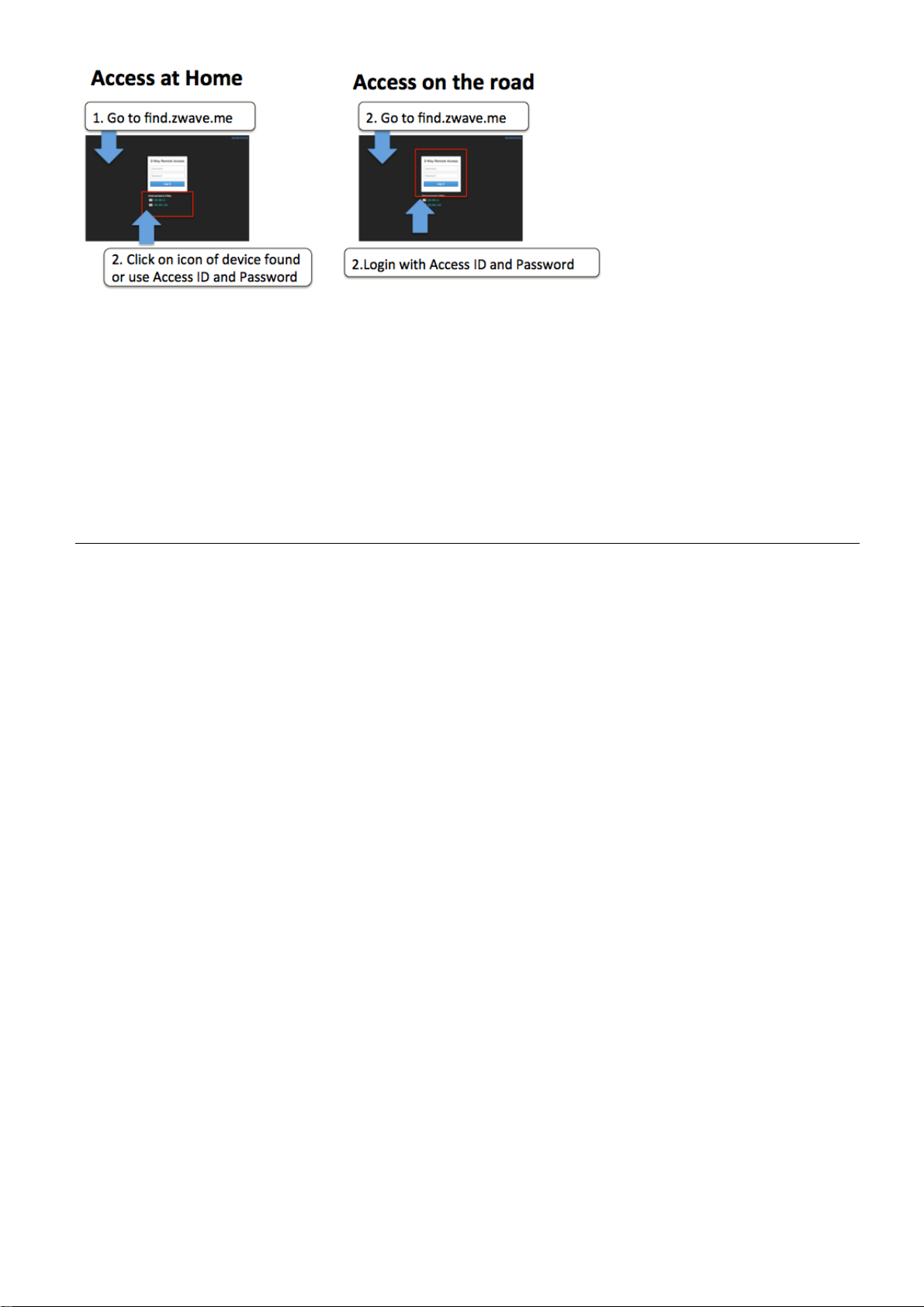
Whenever
address
this
address
even
any
remote accesscapabilityanymore.
may have
sametime
you
accessfind.zwave.me
will
leadyouright
can
be used
turn off theconnectionto thefind.zwave.meservicebut be aware that
difficultytofindthe new address. He nce we recommendusingfind.zwave.me.
we wantyou to have
to your Smart
for
directIPaccess withoutusingthefind.zwave.meservice.
100% control of any
again and
Home UserInterface.
Also in
alocal
case theIPaddressof
cloud service usageofyoursystem.
Z-Boxisfoundclicking
If your Pi
on
the
IP
usesafixedIPaddress
You can
you will not
your
Z-Box changes
have
The
you
Z-Wave
This is a
other Z-W av ecertifieddevicesregardlessofvendororyear
all
the enhancedfunctionsofZ-Wave Plus.
Thisdevicecan
environment too.
utomatically.Duringinclusionthe useofsecure environmentcan
a
performance reasonifdesired.In
will actas
In
case thereismore than one controller
synchronous
R
ep
li
Con
in
case that
controllers
Product
Z-Wavestaticcontroller.As acertifiedZ-Wave
communicate
routers
in
c
a
t
i
o
n
and thefollowingpolicyapplies:
trollerInfomenu)every othercontrollerswill
there
toperforma
Information
in a
se
c
u
r
ee
n
v
i
r
onm
If notthecontrollerwill fall
Z-Wave
for
otherdevicesto form aso-calledmeshednetwork.
regardtot
is no
heirknowledgeofthe network .
SIS
and
thisdevice
networkinformationupda
backtothenormalcommunicationmode
all
non-battery powered
in the
(a)incase there
is
Primary
e
n
t
network
query the
C
ont
te.
Plus
device Z-Boxcommunicatingwith
if
the other device supports the secur e
thecontrollers
This iscalled
is a
SIS
r
oller
please re-includ e other
of origin
anditimplement
be suppressed
device
such as
need
Con
SIS
in
the network(check
for
updates.(b)Inthe
to
t
r
o
ll
for
the Z-Box
be kept
e
r
s
rare
Thedevicesupports
catch events
There
Thedevicesupports
generic MultilevelSwitch)todifferentiatereceivingcommands
modern scene control commands. The
SwitchBinary, SwitchMultilevel and SceneActivation)that do
allow
is no
commandreceptiononly.
from
other action
the
commandclasses‘
devices usingthese commandclassestotrigger actionsinthecontrolle
performed
lifeline(associationgroup
thanchangingvaluesinth
Sw
i
t
chM
1, max 3nodes)
channels
ul
t
il
ev
el
’,
supportthesame commandclasses(Basic
notperformanyrealactionbu
‘
Sw
i
t
c
hB
i
na
edevice
and
16
fromdevices
r
y
’
and
‘
Ba
sic
’
to
data
objects
channels (simulatin g
not
abletosend
.
t
r.
a
,
8
Page 9
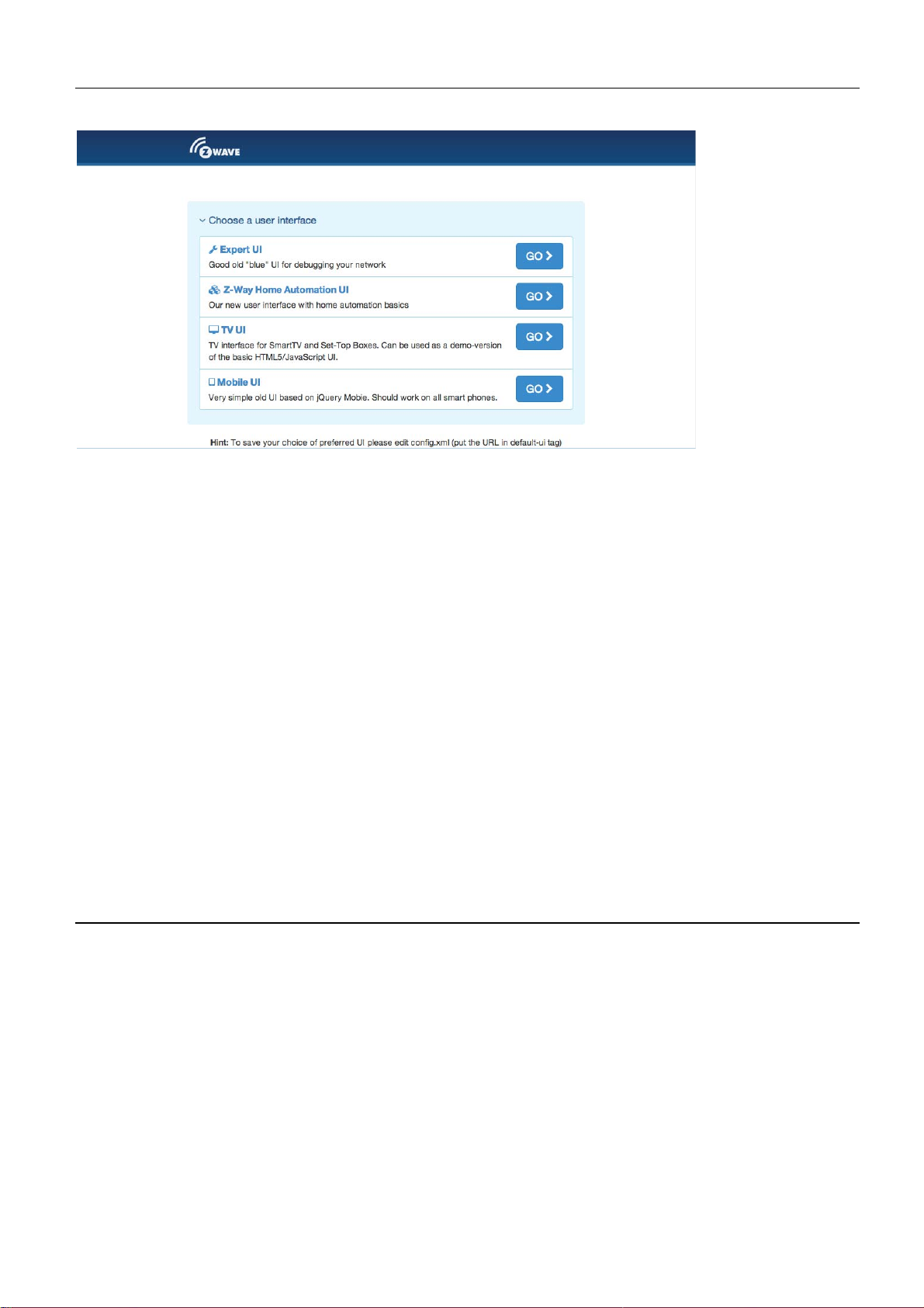
Various
User
Interfaces
of
Z-Box
When going
you
liketowork
manage
usage
native
Just visit
TheZ-
the
of
thewhole
apps
theGoogleApp storeorthe
Wave
tohttp://YOURIP:
with. The two
Z-WaveNetwork)andtheZ-
system. Above andbeyond
you find in th e
Expert
8083
mostinteresting
app storestoaccess
you will
iOS
UI
seeaselection
UIs
are
WayHomeA
this you can
thesystem.
app store
menu
theZ-WaveExpertUI
utomation userinterface
fornativeapps
to
choose
use various mobileplatform
with
the name“Z-Way”
the
web based
(to
create
for
day-by-day
UI
and
.
The Z-W av e Expert U serInterfaceisdesignedforinstallers,te
users
Z-Wave
Z-Wave network.
that kno w how to builtandmaintainaZ-Wavebasedwirele
specificlanguage and
It allows
Add
Configure
Operate
Manage
(
inclu
Accessalldatage
andactionstothe
to
d
e
)
Z-Wavedevices
Z-Wavedevices
Assoc
offers detailed insight
and
remove(exclude)Z-Wave
.
.
i
a
tions
betweenwirelessdevices.
neratedby
device
thedevices
.
into
the
devicesand manage thenetwork.
andperformallkindoffunctions
chnicallysavvypeople
ss network. Henceituses some
work
and data structureifthe
and other
9
Page 10

Lookbehindthesceneinto
timings
andsoftwaredevelopment
The
Z-Wave ExpertUIdoe
d
automation
of
theZ-Wavecontrolstack. This isparticularlyusefulfordebugging
snotprovide
.Pleasereferto
the data structures, routing mechanisms and
.
any acces
other UserInterfacesfor
stohigherorderbusinesslogi c a n
thesefunctions
.
TheUIoffers a
Control:
Device:Accesstoinformation
Configuration:
Network:Add and removedevicesand manage thenetwork.
The
top
the Expe r tUIand
upperrightside
the
beat
to
thesystem
Allvalues
value
stampindicatesthat andupdaterequest
ofstatusinformation
home screen
Accesstofunctionsof
level also has alanguage
will not
shows
.
showninthe Z-Wave ExpertUIare assigned
and four
Configure
be used by other web based
thetime
was
top men uitems:
thedevicesafterinclusionifneeded
selector.Please
on
thecontrollerdevice.Itsupdate serves
received
HomeScreen
thewirelessdevicesincludedinthenetwork.
aboutdevices.
.
we aware that
or
app basedUIs.
to atime
from
the wireless network.Ared
from
thecontrollerfor thisvalueispendin
thisselectionis onlyvalid
Thetiminginfo on
as a
stampindicatingwhen the
color of
thetime
for
heart
g.
The
home screen
where the user
The
NetworkInformation
network
list
device
and giv in g guidance
and howmanyof
devices that have problems: the
failed.
offers
orinstaller
Clicking
some high
can
box
them are
on
the statem ent
forremediatio
levelinformation
leave importan tinformationforfutureuse.
offers
somestatistics
mains or
batteryis
n.
battery operated . The network healt
down, the interview
will
lead
about
about
to a
thesoftwareandanotepad
the
helppageexpla
numberofdevices
is not
iningthe prob le m s
in the
hbox
completeorthe
will
10
Page 11

Control
The
Control Tab
in
caseofsensorsormeters.Incase thecontroloptionsoffered
refertothe Expert Comman d Tabas
supported
Switc
h
allows
by
thedevice.
operating th e variou s typesofdevices and shows the reported values
partoftheConfiguration
here are
menu
not
for a fu ll
sufficient please
setoffunctions
The switchdialoglists alldevicesof the
control
the
switch
react
will
capab
timeof
(if
mains
on a Switch All ON or Switch All Off
reacttothe com mandshown.
ilities.
the
power eddevice).A‘SwitchAll’Iconshowswhether
Thedevicename andId
last
status update.The“Update” buttonforces
networksupportingswitching,dimmeror
and the curren t statusofthe
animmediateupdateofthe
command.Agreentriangle
or not
indicates that th e device
switch is
thespecificdevice
motor
given and
will
All actuators can be switched on or off. Dimmer and motors controls can be operated using a slider. For
dimmer th ere is a button “On” and “Full”. “Full” turns the dimmer always to 100 % diming value while
“On” will turn to the last dimming state before the dimmer was turned off. Clicking on th e table heads
reorders the table view of the data.
Sensors
The
sensordialoglists alldevicesof the
andid,the
Date/timecolumnindicateswhen thegivensensorvaluewasreceived.Itspo
sensor upd a te bu t bearinmindthat battery operateddevice
a
next
typeofthe sensor, th eactualsensorvalue
wakeup
.
networkprovidingsensorinformation.Devicename
and the senso rscaleislisted.The
ssibleto call for
will only
respondafterthe
11
Page 12

Meter
s
The
meterdialoglists alldevicesof the
Device
listed. The Date/tim e columnindicateswhen thegive
possible
respondafterthe next wakeup . Clickin g
d
ata
nameand
to call for a
.
id,
the typeofthe meter, theactual
meter update but bear
networkproviding(accumulating)meterinformation.
in m ind
on
thetableheads reorders thetableviewof
meter value and the me te r
nsensor
thatbatteryoperated
value was
received.It
device
scale is
s
will only
the
Thermostat
The
thermosta tdialoglists all
the curre nt
setpointtemperature
changed
table
s
setpointtempera tu reisshown. TheDate/timecolumnindicates
using
view of thedata
the‘+’or
thermostat devicesofthe ne tw ork.Device
was
transferredtothedevice
‘-‘
buttonsorthe slider. Clickin g
.
.Thesetpointtemperature
onthetableheads reorde rs
name andid
when thegive
can
and
n
be
the
12
Page 13

Attention:
d
evices.Ifacoolingand a heatingf
expert com mandsection
DoorLocks
The
door
status
Clicking
The tem peraturevaluedoes
for
moreprecise
lockdialoglists all
of thelockand
on
thetableheads reorde rs
lasttimeofthe changeofthe statusislisted.
door
Device
notdifferentiate
unction
lockdevicesof the
thetableview of thedata
shall
havediffer
comm andsettings.
network.Devicename
betweenheatingandcoolin
ent setpointsplease
andid,the
.
refer to the
g
current
TheDeviceTabgives
devices
Status
Thisdialogshows
id
between thecontroller
checkmark indicates that the device
that
can
in the
:
and name.Thedate/timeindicates
thecontrollerassumes thedevice
be checkedfortheir
networkandtheiractual status
accesstooverview
theactualnetwork status
and
thisdevice(eitherconfirmedsendingorreception).
network availabili ty byhi
pages
thetimeofthe
is
alive.Ared
not
with
.
of alldevices.
beingactive
more
signindicate
tting
detailedinformationabout
All
devices are listed by their node
lastsuccessfulcommunication
s
anymore.
the “Checkconnectivity”bu
Mains
The green
powereddevice
tto
n.
the
s
s
In
case the device interview andconfigurationwas notperformedproperly
mark icon will
detailsof
as well. Forbatterywakeup and the current wakeup status
tableviewofthe data.
indicate
theinterviewprocess.
this.
Clicking
operateddevice
Clicking
on
thequestion
The
correctloadingof aDeviceDescription
thetimeofthe
is
shown. Clicki n g
on
thetableheads reorders thetableview of
mark will
last
wakeup, the timeofthe next
openawindowdisplaying
on
thetableheads
a little
question
Fileisindicated
reorders the
thedata
the
.
13
Page 14

Batter
y
This
dialoggives
network.
including update timeisshownaswellasthe
“Update”
after the next wakeupofthedevice.
thedata
Devicesarelisted by name and
button
.
anoverviewof the
will
requestastatus update
battery status
id. The last
Clicking
of thebattery-
reported battery
number and typeofbatteryifknown. The
from
thedevice.The
on
the table heads reorders thetable
operateddevicesin
level(0…
new
status
100
will
beavailable
%)
view
the
of
TypeInf
The
Z-WavefunctionssuchasSecurityand Z-Wave
applicationversionandtheirdevicetypeindicatorisshown
Clicking
o
type
infodialog
on
the tableheads reo r de r s thetable
lists al ldevicesof
the network an dindicatesifthey support enhanced
Plus.TheirZ-Waveprotocolversion,their
viewofthedata
forinformationpurposes too.
.
Association
This overview
lifelines
can be
page
(association
hidden
of the
page
if
device
shows the
to the
needed.
to
change association
current association
gateway
A
‚Change’
to
report
button
set in the
status
changes
leads right to the
settings.
network.
and
The
heard
Configuration
beat)
14
Page 15

Configuration
The Configuration Tab allows configuring the functions of the device. Pick the device to be configured from
the drop down list to access four tabs.
Int
erview
Thedevicei
c
ontroller
description record
not
be
deviceandloadthedescriptionrecordabutton “Choo seDeviceDescriptionRecord”
to do th is
Theinterviewstage
splittingit intothedifferent
successfulinterview,
queue
There are
deepsl
the whole
ntervi
ew section
tries togetinformationabout the device.Incase the controller findadevice
for
thedeviceit willdisplayfurtherinformation
obtainedfrom
manually
to
becompleted
a few
eeptoo
reasons
interview.
thedeviceitself.Ifthesoftware
.
linegivesinformation
‘0’apermanent
early to has
Thebutto
shows
commandclasses
.
why aninterviewis notcomplete:Inmostcases
someproblems.
the
result
about
failanda‘.’
n“RequestNIF”
of thedevicei
the
progress
supported
that th is
The
button “ForceInterview”
requestsaNodeInformation
nterview.In
about thedevice
willnotautomaticallyrecognize
of thedevicei
by
the
device.‘+’indicate
command
class is still in
this
process
nterviewby
thedeviceswent to
allows
Frame
the
thewaitin
re-doin g
from
that
the
allows
a
can
g
15
Page 16

thedevice
differentcommandclassesfoundduringtheinterview.Itisalsopossibletoforcethe
the
interviewof acertaincommand
and th e Button “Showinterviewresults”
classonly.
allowsdisplayingtheinformation
about
The only
inclusionthesoftware
this
Configuratio
The
There are
are displayed
shown
shows
update
configurationoption
generatedageneric
name. Thegivennameshould
n
configurationtab
four
more commandclassesthat
ifthecertaindevicesupports
in
theUIand
when thetime
may
be delayedifthedeviceifbattery operated
•
Wakeup:Definethe
of
thewakeup
secondsunless
cases th e nod e
should
may
wakeup
•
Pr
otection:In
of
classactually
tab
•
SwitchAl
broadcasttoallswitches
device
“sectionaslittle
•
Configuration :In
aboutfurtherconfigurationoptions
maygive
description
device
comman d
not
change.
timeas
the device –
for acomplete
lconfiguration:
to such a “Switch All”command.
moredescriptiveinformationabout theconfigurationvalue.
does hav econfigurationoptionsitspossibletoset
allows
can
beupdated
where
sequence. Thecontrollerwill set a
thedevicessetsadifferent
idof
be changed.Incase
A tooltipon
reporte d b y thedevice
case the device sup p o rts
thebehavior
offers more
gray/greenic
case the controller
of
the deviceisfoundnoconfigurationoptionsare shown.In
sectio
n.
on this
configuringthedevic
thevalues
wakeupinterval
thecontrolleristhecorrectsettingfor
optionsthan displaye d here, Ref ertothe‘ExpertCommands
setofcontrols.
Z-Wave supports the
tab
is to
name but
be
descriptive
may
it.
using the
wherereceivedfrom
thiscontrolleris only
theinputfield
of thisfunction
anddi
mmers.This
on.
button“Update
and the node
Thesettingis alsodisplayed
can
these
change
e.
needadditionalconfigurationwork
Theactual
thegiven
it ishighly
bit not toolon
dataofthedifferentsections
thedevice(Beware,
an in
is of
standard wakeu ptime
minimal or
maximal
seco
shows theallowed
.
local
protection–means suppre ssin g
can
be defined.Theprotectioncommand
socalledswitch allfunctionas a
setupdefinesthereactionofthe
identify the device and findsinformatio
optionsare shown.
name
g.
fromdevice”Atimeindicatio
deepsleepstate)
the
n
of thedevice.During
recommended
maincontrollertaking
wakeuptime.In
the target nodeid
d
a
r
y
co
n
t
minimum and maximu
in the“Switches
Thelittle
themusingthe expert
r
o
to
that
of 1800
ll
e
r
(i)
If no
case
change
and that
an
thisvalu
local
n
symbol
device
care
most
and
the
are
n
e
m
use
’
16
Page 17

Note:
willactivatethechanges
are stored
manuallyto
For m ains
to
speed up the changeofconfigurationvalues.
powereddevicesand
the next wakeup.Itspossible
within
FLIRSdevice
few seconds.
the button“Applyconfigurationtodevice”
For
battery operated devices the commands
and recommendedtowakeup thedevic
e
Associatio
Associations allow switching a Z-Wave device B (target) as a result of an event in Z-Wave device
A (source). Z- Wave device A offers lists of devices to switches for each event supported. The
list of these events - also called association g roups - and the devices that are associated with
it are shown in the Association tab. In case the information is provided either by the device or
by the device record stored in the software the meaning of the events is written. Otherwise only
event group is shown unnamed. In this case refer to the devices manual for more information
about the association group meaning. The stored devices can be called from the actual device
using a button. The buttons ’+/-’ used to add and remove device from the group. A dialog is
opened and a device can be picked. In case this device has multiple instances an instance drop
down list will appear allowing
to choose the right instance of the target device. The node ID and - if applicable – the instance
id are shown in
the target device list. Move the mouse over the ID to show the complete given name of this
device.
n
17
Page 18

ExpertComman
The
expert commandsectiondisplays the statusvalues
genericway. Ontheleft
In
case there
Clicking
next
name opens
On
informationprovidedby
on
column
therighthandside
ds
hand side thedifferentchannelsofthe devi c e are listed
is only
the number opensadialogshowing
shows
adialog
onechannel(that’sthe case
all
the co m mand classes exposed by the device .Againclicking
with
moreinternal
there
is a list of
the comm and
statusvariableinformation
commands.
classitselfand
and
possible
for
mostdevices)
allinternalvariables
ThisUIis
notoptimized
auto-generated
commands
onlychannel
for
thechannel.
for this
fordaily
comma n dclass
from
usage.
in a
in a
0is
the
very
column.
shown.
The
on
the
.
18
Page 19

FirmwareUpdate
In
case the device supportsafirmware
such afirmwareupdate.
http://IP:PORT/file
availablein raw
memory/processor
be set. The firmwareupdatingprocess
operationduring
It may
Please
berequiredto
refertothe
‘BIN’formator
thistime
The firm ware
or asfileuploadusing thefileuploa
‘HEX’format.Thetargetfieldallowsspecifying
for
the update process.
.
activate the firmware
manual
forfurtherinformationaboutactivation.
update ‘over theair’thisdialogis
can
be providedin two ways:
ddialog.
For
upda ti ng theZ-Wavefirmware parta‘0’
will
take up
update mode
to 10minutes.Please don ’t doany
on
eitherasURLintheformat
The firm w a refilemust
the devicetobe updated.
showntoperform
be
the target
must
other
Network
The
Networksectionof theUIfocuses
informationtobuild,
Control
network control sum marizesall
The
c
ontroller.The
Thedevicemanagement
shows thestatus
thecontroller
and the resp. buttons
time
outafterabout
Another
the
generatedadefaultnameofthe
node
Configuration
p
erformed.
way to
inclusionmode
id.
Clicking
pageisstructured
into
stop theinclusionmode
page where the name
manage andrepair
box allowsincludingandexcludingZ-Wavedevices.Astatusdispla
of thecontroller.The“IncludeDevice”
the
I
nclus
i
o
n
turns into a
20
seconds but
will
stop and the nodeidofthe newdeviceis
on thisdefault
on
the ne twork
thewirelessnetworkofthecontroller.
commands needed
in four
resp
“Stop”function.Theinclusion and exclusion modes
deviceascombination
nameleadstothe
boxes
.
Ex
c
l
u
can always
is t o a c t u allyinclu
can
be changed
.
s
i
on
mode.
beterminatedusingthe
as such
In this
and
and offers
to
manage
resp.“ExcludeDevice”button
case the status display changes
de
anewdevice
of itsprimaryfunction
otherconfigurationtasks can
allcontrols
the
network
“Stop”buttons
shown. Thecontroller
and
and the
turn
will
.
.Inthis
and the new
case
be
y
19
Page 20

Please
work as
a
r
e
caused by
refer to the
e
x
p
e
c
t
e
still
d
d
,
i
ev
i
c
es m
please
n
c
l
u
ded
a
nua
l
on how to do an
e
xc
l
u
de
in
a
di
ff
thedev
ere
i
c
n
t
networ k and
e
first. Mo
inclusion.
r
e
than 90 % of all
can
In
case the inclusion does
i
n
c
l
u
s
then
not
be
i
n
g
i
n
c
not
i
o
n
p
r
o
b
l
e
m
s
l
u
de
d
a
ga
i
n.
The Ex clusionmode
canexcludedevices
functioning.
Failed
In
controllerwillinclude
and the newdeviceisencryptedusingAESencryption.
d
controller
Securityfunctionsofotherdevices
The
thelocal
restoreoperation
if
resultin a
Handle
node”orRemoveFailedn
case the new device supports enh an c ed secu rityfunction
esirednot to
second
the nodeinformationin
To
remove
use thesecurityfunction.Theslider“Forceunsecureinclusion”turns t he
into a
computer .Please
withcare
mode where
box of
possible
also
stops wh en onedevice
from
other networks
nonfunctioningor
ode”.
thedevicesecurely.
allsecurityfunctions
are
the pa ge
mustthereforebeconfirmedinanother messag e
loss of all
.
allows creatingandusingab
note that
the z-wavechipitselfshallbeove
networkrelationshi
too
disappeared
After
notimpacted.
any
restore
wassuccessfullyexcluded.
but the device need be
this all
are suppressed
willoverwritetheexisting
ps an d
Thisfunctio
available
devicespleasereferto
(Security Co mmandClass)this
data exchan ge between thecontrolle
Forperformancereason s
for
theincluded
ackup.
mayrequireare-
The backupfileis
box. A
rwrittenaswell.
and
“Replace
it mays
stored
network.
checkboxdefines
This
operati
inclusio nofdevices.
device
The
on
n
be
.
on
r
Thecontrollermaint
operatingsystemofthe Z-Wavetransceiverchip.
the
The “Rese
d
evicesandallconfigurationsandsettingsare
extreme case.
f
unctionifyouknowwhatyoudo!
tController” turns
enance
Anadditionaldialogrequirestoexplicitly
offers two
thecontrollerback
reset buttons.
The “Z-WaveChipReb
This can
into
factory rese t.
lost. Thisfunction
confirm
oot”
restarts
be donesafely
Allconnectionstoinclude
must
be
thefunction.Onlyusethis
all
thetime
handleswith
.
d
20
Page 21

ThefunctionRemoveFailedNode
withthecontroller.
mark this
such adevice
nodes.Ifthis list is
deviceasfailedandavoidfurthercommunication.Thisfunctionfinally
from
Aftermultiplefailedco
the net workconfiguration.Thedrop down
empty
this is a
allowsremovinganode
mmunications
goodsign!
that is notlongerco
with adevice
list will only sho wIDsoffaile
thecontrollerwill
mmunicatin
g
removes
d
It is alsopo
removingthefailednode
included
offailed
ssibletoReplaceaFailednodewith a
node
nodes.Ifthis list is
has the
same nodeIDas
andadding
empty
this is a
new node .
anew
node.
thefailednode.
goodsign!
Using thisfunction
This is acombinationof
makes sure
The
drop down
list will only showID
the next
s
21
Page 22

Battery o perated
communication
deviceisdefectorgone.
operateddevicesasfailedso
shows
all
battery operate ddevicesbut
devicesare
requests.Hencethecontrollerwill
Thefunction
mainly in
that they
deep-sleep state and
neverautomaticallydetect
“Markbatterydeviceasfailed”manuallymarksbattery
can
be removedorreplaces.The
this
does
not
mean that they arefaile
will not
answer
dropdown
to
if acertain
list
d.
-
The next twofuncti
can
become a
did
notincludeany
functionwhere
dialogon
about
manuallyterminatethemode
The “Change
network
controller statusdialog
The “RequestNIFfrom alldevices”function
InformationFrame
Thefrequencychange buttons
care!Changingthefrequency
about the consequencesofthischange,don’ttouch thebuttons
the upperleft
20
secondsorwhen the
toacontrollerthat
onsdealwith thecontroller
secondarycontrollerin
otherdevicebefore.
it will
acceptinclusion requestsfr
handsideshows
device
.
Controller”functionactively
will
beincludedusing thenormalinclusionprocess.
shows
from alldevicesof
themode
allowchangingthe operatingfrequencyofZ-Box. Handle
mayresultinmalfunctionof your
another network.
thenetwork.
role
in the
Clicking t h e“Learn”button
om othercontrollers.
this
status. TheLearnmode
wasincludedsuccessfully.Itis also
hands over theroleoftheprimarycontrollerofthe
and
itstermination.
is just aconvenient
network.
This is onlypo
way toretrieveaNode
network.
With ”Learn”thiscontrolle
ssibleif thiscontrolle
turns
thecontroller
Thecontroller
will
possible
If you
!
time
outafter
The
areuncertain
in a
status
to
r
r
with
The Z-Box
withZ-Wavetransceiverswill
moment there are three
frequencygroups.Changing
attenuationofthe
Changing
include d devices b ut
usefultochangefrequencies
Routin
hardware
between thelines
g
can
be changed
different
signal
but
also
resultissevere attenuationofthe w ireless signal.
into eve r yvalidfrequencyhowever the antenna
attenuate thewireless signalfor
typesofantenna
thefrequency
will
stop
any
will not onlyresultincommunicationproble
fordebugging
within
communication
purposes butagain:Handlewithcare
filtersallowingoperationinthe three
theline(e.g. from EU toCN)will not
wrongfrequencies.At
in anetworkalreadyes
ms
withexistin
It may still
filter used
the
result
tablished.
g
be
!
in
22
Page 23

23
Page 24

Thistableshows
node arelisted.Dark
neighborhoods
connection
just ok. This can
indicated
thatth
currentconfigurationofthe ne tworkrequires
each other duetoanassociationrelationship.
scan its
table.
aninsufficientco
e
neighborhood
the
neighborhoo drelationshipofdevices.Theid,the
green indicates
anddon’
needs one router between.Yellowcolorindicates
beachieved
tneed
bylonger
mm
unication
and
report ba cktheresultto
that
any
otherdevice
butmultiple
the
link. Alittleblackdot
name
twodevicesare indirectwirele
to forwardtheirsignals.ALightgreen
thatthecommunicationroute
routes.Ared
these
two
The‘Update’
update
nodestoco
its ownlineof
color
betweentw
in thecoloredfieldindicat
mmunicatewith
button
calls thedeviceto
and the
ss
the routing
type
of the
onodes
es
is
Reorganizati
Thereorganization
problems.
fixes
of
thereorganizationisshownina
on
page controlsanalgorithm
With
checkboxesdifferent
log and
that reorganizes
stagesofthe algorithm
can
be downloaded
.
the
networkrelationshipsand
can
beselected.Theresult
TimingInfo
The Timing
c
ontrollerand
shown
shown.
controllerand
shown andcolor-coded.A
tab shows some
otherdevices.All
in a list.
This cangive
The numberofpackets
this
anindicationabout thestab
device.
veryvaluabletiminginformationofcomm
otherdevices
and the percentageofsuccessfulcommunicatio
On
therighthandside
red numberindicates
thecontroller
ilityofthecommunicationlink
thetimingdelayofeachcommunicationis
that
thiscommunicationfinallyfailed.
hascommunicated
unicati
ons
between
with
between the
the
are
nare
A
24
Page 25

co
mmunicationwithoutreroutingattemptsasshownasgreen andarerouting
codedinbla
problem
device
particularly
just
ck.Thefact
in
the ne twork
went
back tosleep
whencombinedwith
thatacommunicationfailed(red)mayindicate
or inthedevice.Itis
too fast.
Z-Wavepros
theroutingtable.
however
can
also
read
that there
possible
a lot out of thistiminginformatio
thatabattery operated
attempt
is a
severe
is
n
ControllerInf
o
This dialog shows some internal technical data of the controller h ardware used. The first box offers
some deep insight into the dynamics of the controller software. It visualizes the job queue of the
system. Every communication attempt of the controller is queues into a job queue and then handed
over to the Z-Wave chip for execution. The list shows the jobs pending and the jobs that are
completed or failed.
Alegend
value
job
target node
process
informs
countsbackfrom 20
will stays i n
and the real Bytes of the
about themeaningof
seconds once thejobwas
the queue m arke das
ID,adescriptionof
message a re sh ownaswell
thedifferentflagsn, U, D, E, S
sent. Even when
done
thecommunication message,ainformationabout the
(D)
for
some moretime
.
and
W.
Thetimeou
it wascompletedthe
to allowinspection
t
.The
25
Page 26

The
secondblockgives
Z-Wave
releaseinformationof
and
transceiverhardware used,firmwarerunningon
debugging.
detailedinformationabout
theZ-Waysoftware.
Thisinformationmay
the
Role
of thecontroller
the Z-Wavetransceiverand the
be needed duringsupport
in the
network,
the
Thecontroller
accessingthedevicespecific
third buttongives
developer
is aspecial
s.
access
node
to thecontrollerspecific
in the
dataofthecontrollerand issueaNodeInformation
network but
still a
node. Therefore buttons
data.
Most of
these data
is onlyrelevant
allow
Frame.
A
to
26
Page 27

The lastblock
transceiver
shows
and
Z- Way. ‘Notimp
the
availability
of thefunctioncalls on the se rial A PI
lemented’
functionindicatedby thefunctionIDor
nameindicated
but
thetransceiversfirmware
that
Z-Way isabletouse
did
not
reporttooffer
means that
does
not
thisfunctio
Z-Way iseither
make
any
n
thisservice
use
.
of it. A
between
the
Z-Wave
notknowingabout the
redfunction
callid
or
Z-WaveTerm
Thefollowing
•
Staticcontroller is a Z-Wave dev ic e with capab ilities to manage the network available on
fixed location in the
Secure
•
enhanc
•
ControllerReplicati
•
SIS:
•
PrimaryController:Ifno SISis
ableto
•
SecondaryController:Ifno SISis
controllerarecalledsecondary
•
Inclus
•
Exclusion: the process of removing Z-Wave device s from the
•
Association is acontrolrelationship betweenacontrolli n g device andacontrolleddevic
•
Association Groupis the list ofdevicescontroller
•
SwitchMultilevel,Swi
•
NodeInformationFrame
to
s
Z-Wave term s are used
home
environmen t:Forsensitiveapplications
ed
encryptionwrappingdefined
on:
Copy theinformationofonecontrollertoanothercontroller
The central
include newdevices
ion: the proces s of bringing new Z-Wave devices into a
announce
databaseofnodes andids
tchBinaryandBasicare certain commandclasses
itscapab
in thismanual:
in the
.
present one controller beco mes the primary controller
present,
is aspecialwireless
ilities
andfunctions
all
othercontrollers
messageissuedbyaZ-Wavedevice
.
like
door
lockcontrol
command
byassociation
class
network
network
Z-.Wave
Security
than theprimary
.
a
offers an
only
e
CommandClassesControlled/Supported
Alarm V2 Controlled, Alarm Sensor V1 Controlled , All Sw itch V1 Controlled, Application Status V1 Supported, Association V2
Supported and Controlled, Association Group Information V1 Supported and Controlled, Basic V1 Supported + Con trolled,
Battery V1 Controlled, Binar y Sensor V2 Controlled, Bina r y S w itch V1 Controlled, Central Scene V1 Controlled, Climate Control V 1,
Controlled, Clock V1 Supported and Controlled, Configuration V1 Controlled, CRC16 V1 Supported + Controlled, Device Reset
:
27
Page 28

Supported + Controlled, Door Lock V1 Controlled, Door Lock Logging V1 Controlled, Firmware Update V1 Controlled, Indicator
V1 Controlled, Manufacturer Specific V1 Supported + Controlled, Meter V3 Controlled, Meter Table V1 Controlled, Multichann e l
V3 Controlled, Multichannel Association V 2 C ontrolled, Multicommand V1
Controlled, Multilevel Sensor V6 Controlled, Multilevel Switch V3 Controlled + Supported, Node Naming V1 Controlled +
Supported,
Powerlevel V1 Supported + Controlled, Protection V2 Controlled, Scene Activation V1 Supported + Controlled, Scene Actuator
Conf V 1
Controlled, Scene Controller Conf V1 Controlled, Security V1 Supported and Controlled, Sensor Configuration V1 Controlled,
Thermostat Fan
Mode V3 Controlled, Thermostat Fan State V3 Controlled, Thermostats Mode V 3 Controlled, Thermostat Operating State V1
Controlled,
Thermostat Setpo int V3 Controlled, Time V2 Supported + Controlled, Time Parameter V1 Controlled, User Code V1 Controlled,
Version V2
Supported + Controlled, Wakeup V2 Controlled, Z-Wave Plus V1 Supported + Co ntrolled
Support
Should you encounter any problem, please give us an opportunity to address it before returning this
product. Most questions regarding Z-Wave wireless communication standard can be answered through
the international community at www.z-wave.info
FCC STATEMENT :
This device complies with Part 15 of the FCC Rules. Operation is subject to the following two conditions:
(1) This device may not cause harmful interference, and
(2) This device must accept any interference received, including interference that may cause undesired
operation.
Warning: Changes or modifications not expressly approved by the party responsible for compliance
could void the user's authority to operate the equipment.
NOTE: This equipment has been tested and found to comply with the limits for a Class B digital device,
pursuant to Part 15 of the FCC Rules. These limits are designed to provide reasonable protection
against harmful interference in a residential installation. This equipment generates uses and can radiate
radio frequency energy and, if not installed and used in accordance with the instructions, may cause
harmful interference to radio communications. However, there is no guarantee that interference will not
occur in a particular installation. If this equipment does cause harmful interference to radio or television
reception, which can be determined by turning the equipment off and on, the user is encouraged to try
to correct the interference by one or more of the following measures:
Reorient or relocate the receiving antenna.
Increase the separation between the equipment and receiver.
Connect the equipment into an outlet on a circuit different from that to which the receiver is
connected.
Consult the dealer or an experienced radio/TV technician for he lp.
FCC Radiation Exposure Statement:
This equipment complies with FCC radiation exposure limits set forth for an uncontrolled environment.
This equipment should be installed and operated with minimum distance 20cm between the radiator &
your body.
28
 Loading...