

Page 1
Shenzhen Elephant Robotics Technology Co., Ltd.
Elephant Robotics User Manual
Panda Series Robot
Version 1.0
Language: English
Compiled in 2019/01
© Copyright 2017-2019 Shenzhen Elephant Robotics Technology Co., Ltd.
All rights reserved.
Page 2

Shenzhen Elephant Robotics Technology Co., Ltd.
Copyright Declaration
No unit or individual may extract, compile, translate or reproduce any
contents of this manual (eg: technical documentation, software, etc.), nor
disseminate in any form (including materials and publications) without the
written permission of Shenzhen Elephant Robotics Technology Co., Ltd.
(hereinafter referred to as “Elephant Robotics”).
In addition, the product information and related resources mentioned in
this manual are for reference only and the contents are subject to change
without notice.
Except as expressly stated in this manual, nothing in this manual should be
construed as any warranty or guarantee by the Elephant Robotics of personal
loss, damage to property, or fitness for a particular purpose.
All rights reserved!
Page 3

Shenzhen Elephant Robotics Technology Co., Ltd.
Content
Overview to the manual...........................................................................................................................1
About the manual...................................................................................................................................1
Reading objects of the manual...............................................................................................................1
How to use............................................................................................................................................1
Main contents of the manual
Before the official reading of the manual
1 Security.................................................................................................................................................3
1.1 Introduction......................................................................................................................................3
1.2 Safety alert symbol description....................................................................................................... 3
1.3 Hazard identification....................................................................................................................... 4
1.4 Safety Precautions
1.5 Label, nameplate introduction
1.5.1 Nameplate.......................................................................................................................7
1.5.2 Label...............................................................................................................................7
1.6 Avoid misuse................................................................................................................................... 8
1.7 Emergency stop
1.7.1 Emergency button...........................................................................................................8
1.7.2 Collision checking..........................................................................................................9
1.8 Urgent handling...............................................................................................................................9
2 About product
2.1 Overview to the robot system
2.2 Robot
2.3 Scope of work
2.4 Active load
2.5 Technical Parameter Table
3 Environment and installation..............................................................................................................16
3.1 Transportation and storage............................................................................................................16
3.2 Open box examination...................................................................................................................16
3.3 Working environment and conditions
3.4 Installation
3.5 Electrical connections
3.6 System startup debugging..............................................................................................................22
3.7 IO Board........................................................................................................................................23
4 Calibration
5 Maintenance
5.1 On the safety of maintenance........................................................................................................ 32
5.2 Maintenance plan...........................................................................................................................33
5.3 Who to contact...............................................................................................................................33
6 Repair................................................................................................................................................. 34
.....................................................................................................................................
.............................................................................................................................................
2.2.1 Characteristics of the robot.......................................................................................... 12
2.2.2 Model............................................................................................................................12
2.2.3 Robot joint introduction............................................................................................... 13
3.4.1 Installation requirements..............................................................................................17
3.4.2 Installation....................................................................................................................17
3.5.1 Cable connection
3.7.1 IO board introduction...................................................................................................23
3.7.2 IO port principle and application..................................................................................28
..........................................................................................................................................
.......................................................................................................................................
...............................................................................................................................
................................................................................................................................
.....................................................................................................................................
.....................................................................................................................................
.................................................................................................................
..............................................................................................
...........................................................................................................................
.........................................................................................................
11
........................................................................................................
............................................................................................................
...........................................................................................
....................................................................................................................
..........................................................................................................
21
31
32
1
2
5
7
8
11
12
14
14
14
17
17
21
Page 4

Shenzhen Elephant Robotics Technology Co., Ltd.
1
Those who install/debug/maintain the Panda series robot must be trained in
Elephant Robotics and have the mechanical and electronic knowledge required for
the above work.
Overview to the manual
About the manual
Welcome to use Panda series robot and thank you for your purchase.
This manual describes the precautions for proper installation and use of the
Panda series robot.
Please read this manual and other related manuals carefully before
installing this robot system. After reading, please keep it in a safe place so that
you can access it at any time.
Reading objects of the manual
This manual is targeted to:
installer.
Debugger.
Maintenance staff.
How to use
This manual should be used when doing the following works:
Installation work: Move the robot to the working position and fix it to
the base according to the installation instructions.
Debugging: Debugging the robot to work status.
Maintenance work: regular maintenance robot system to ensure its
normal functioning. When the robot malfunctions due to environmental
influences or improper operation of the user, or a certain component of
the robot system exceeds the normal service life, the robot needs to be
repaired.
Main contents of the manual
Precautions for safe use of the robot.
Mechanical, electrical installation and commissioning of the robot.
Maintenance and repair of the robot.
Page 5

Shenzhen Elephant Robotics Technology Co., Ltd.
2
Before the official reading of the manual
Before officially read the manual, users need to know something about it:
1,About the robot system
The robot system includes a collaborative robot body, a controller (Core
control system), and a teach pendant (Panda OS operating system). It can work
safely with workers and independently complete the processes of loading,
unloading, testing, testing and packaging in industrial manufacturing.
2,About product warranty
During the warranty period of the delivered product, the company will only
repair the failures that occur when the robot is normally used. However, in the
following cases, the customer will be charged for repairs (even during the
warranty period):
1) Damage or malfunction caused by incorrect use and improper use of the
manual.
2) Failure caused by unauthorized removal by the customer.
3) Damage caused by improper adjustment or unauthorized repair.
4) Damage caused by natural disasters such as earthquakes and floods.
Therefore, please operate the robot in strict accordance with the
instructions in this manual and related manuals.
3,About help
For any questions or suggestions on the contents of the manual, you can
query on the official website of the Elephant Robotics to submit the relevant
information: https://www.elephantrobotics.cn.
Page 6

Shenzhen Elephant Robotics Technology Co., Ltd.
3
Danger: A dangerous situation that is likely to result in death or serious
injury if not avoided.
1 Security
1.1 Introduction
1,Introduction to this chapter
This chapter details general safety information for people who perform
installation, maintenance, and repair work on Panda series robot. Please read
and understand the contents and precautions of this chapter before handling,
installation and use.
As described in GB 11291.1-2011, whether it is a robot manufacturer,
system integrator, or individual user, it is necessary to carry out hazard
identification and risk assessment before using the robot. It is required to
conduct a hazard analysis to identify any hazards that may arise; and for hazards
identified in hazard identification, a risk assessment should be performed to
maximize personal safety and property safety.
This chapter provides a basic guide to safe use by introducing different
safety alert symbols and precautions.
2,Interpretation of related terms
1) Collaborative operation
A specially designed robot that works directly with people in a defined
workspace.
2) Collaborative workspace
In the safety protection space of the robot work unit, the robot and the
person can complete the task at the same time in the production activity.
1.2 Safety alert symbol description
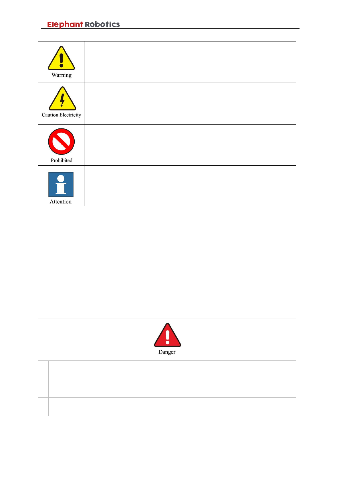
As shown in Table 1-1, this section describes the safety alert symbols used
in this manual. You can find the corresponding symbols described in this
chapter in other chapters, please note the meaning of these symbols and their
meanings.
Table1- 1 Safety Warning Symbol Table
Page 7
Shenzhen Elephant Robotics Technology Co., Ltd.
4
WARNING: Conditions that may cause a hazard that, if not avoided,
could result in personal injury or serious damage to the equipment.
Be careful of electric shock: It may cause dangerous use of electricity. If it
is not avoided, it may cause personal injury or serious damage to
equipment.
Prohibited: Things that are not allowed to do.
Caution: Important things to be noted.
1
Personal injury or robot damage caused by incorrect operation during robot handling.
2
Personal injury or robot damage caused because the robot is not fixed as required, for
example, the screw is not screwed or tightened, and the base is not enough to stably
support the robot for high-speed movement, causing the robot to tip down.
3
Failure to perform proper safety function configuration of the robot, or installation of
safety protection tools, etc., may cause the safety function of the robot to fail.
1.3 Hazard identification
The safety of the collaborative robot is based on the premise of proper
configuration and use of the robot, and even if all safety instructions are
observed, the injury or damage caused by the operator may still occur.
Therefore, it is very important to understand the safety hazards of robot use,
which is beneficial to prevent problems before they occur.
Tables 1-2~4 below are common safety hazards that may exist in the
context of using robots:
Table1- 2 Dangerous safety hazards
Page 8

Shenzhen Elephant Robotics Technology Co., Ltd.
5
1
Play around the robot, you may be hit by a running robot, or be tripped by an obstacle
such as a cable to cause personal injury.
2
Unauthorized personnel change the security configuration parameters, causing the
safety function to fail or danger.
3
Scratches and punctures caused by sharp surfaces such as other devices in the work
environment or robot end effector.
4
The robot is a precision machine and pedaling may cause damage to the robot.
5
If the clamp is not in place or before the power supply of the robot is turned off or the
gas source is turned off (it is not determined whether the end effector firmly holds the
object without falling off due to loss of power). If the clamped object is not removed,
it may cause danger, such as people being injured by crashing.
6
There is a risk of accidental movement of the robot. Under no circumstances should
you stand under any axis of the robot!
7
The robot is a precision machine. If it is not placed smoothly during handling, it may
cause vibration and may cause damage to the internal components of the robot.
1
Using a non-original cable may pose an unknown hazard.
2
Contact with liquids by electrical equipment may result in a risk of electric leakage.
3
There may be an electric shock hazard when the electrical connection is incorrect.
4
Be sure to handle replacement work after turning off the power to the controller and
related equipment and unplugging the power cord. If the work is performed while the
power is on, it may cause electric shock or malfunction.
Table1- 3 Warning level security risks
Table1- 4 Potential safety hazards that may result in electric shock
1.4 Safety Precautions
In general, compared with ordinary machinery, robots have the
characteristics of larger working range and faster speed, so they are
accompanied by the dangers that ordinary machinery does not have. When
installing, using, and maintaining the robot, please pay attention to the
following items shown in Table 1-5 and Table 1-6 (the followings are some of
the common precautions listed):
Page 9

Shenzhen Elephant Robotics Technology Co., Ltd.
6
1
It is forbidden to modify the robot or use non-original accessories.
2
Untrained non-professionals are prohibited from entering the robot work area at will,
pressing any button or doing other operations at will.
3
The relevant personnel shall not maintain, repair or use the robot after being affected
by drinking, taking drugs or stimulating drugs.
1
Anyone responsible for installing and maintaining the robot must read and follow
these safety instructions.
2
Ensure that safety measures and robot safety configuration parameters are defined as
required in the risk assessment to protect programmers, operators, and bystanders.
3
Production operators should not loosen long hair (long hair must be picked up) and
wear a work cap, not wearing jewelry.
4
Operators operating in conjunction with the robot must be familiar with and
understand the content and exact location of the various warning signs and warning
symbols on the equipment and ensure that all warning signs and warning symbols are
complete and clear, and that all safety devices are secured before opening and starting
the equipment. And make sure the relevant accessories are normal and no one is in a
dangerous location where the equipment is activated. When the robot runs
abnormally, it should be stopped immediately and the situation must be reported it in
time.
5
The operator must clarify the scope of operation, commissioning, maintenance and
repair. The operator is not allowed to change the operating procedures and trials at
will, and other personnel are not allowed to enter the collaborative operation space
and danger zone.
6
When repairing work, operators must hang the warning sign to enter the collaborative
operation space.
7
When the operator enters the safety zone of the equipment protected by the safety
guard door, it shall be absolutely guaranteed that the safety guard door will always
open when working in the area, and the door must be in an unlocked position.
8
When the operator is in production, it should be ensured that each starting device is
normal and cannot be started at will.
9
When the maintenance and operation personnel perform maintenance on the
Table1- 5 Safety precautions on acts that need to be banned
Table1- 6 General safety precautions
Page 10

Shenzhen Elephant Robotics Technology Co., Ltd.
7
equipment, the main power switch must be turned off to perform maintenance work.
10
No items should be stacked in the robot working area, and no debris should be placed
in the control box.
11
After the operation is completed, the safety protection door should be closed
immediately, and the various switches of gas and electricity should be closed
according to the procedure, and the work site should be cleaned up.
12
Do not shake the robot and hang heavy objects on the robot.
13
No dangerous behaviors or games around the robot.
14
After installing the robot, make sure the robot is fixed on a stable surface for
subsequent operations.
15
Make sure that the robot does not collide with itself or other objects during running.
16
If the robot is damaged, do not continue to use it.
17
Please use the robot within the robot's parameter range and service life, otherwise it
will cause serious safety problems.
18
After the emergency stop state is canceled, and before the servo power is turned on, it
is necessary to remove the obstacles and faults that cause the emergency stop, and
then turn on the servo power.
19
Please pay attention to the rotating shaft of the robot to prevent the cable and the air
tube from being entangled. Keep a distance from the shaft to prevent hair or clothing
from getting entangled.
1.5 Label, nameplate introduction
1.5.1 Nameplate
There are two types of nameplates used in the robot system. The robot
body and power box have different nameplates. The nameplate records some
basic information about the product. It should be noted that the production
number on the nameplate is unique. That is to say, each product has a unique ID,
which is an important basis for distinguishing each product, and is also
important information to be provided when applying for maintenance.
1.5.2 Label
Robots are high-precision equipment, and they are more dangerous than
ordinary machines when they are unfamiliar or not in accordance with the
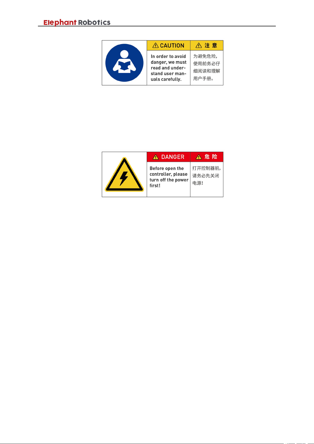
manual. As shown in Figure 1-1, the labels are attached to the power box to
remind the operator to read the relevant operating manual before use.
Page 11
Shenzhen Elephant Robotics Technology Co., Ltd.
8
Figure 1- 1 Reading manual before the operation
The power box provides power to the entire robot system and must be
operated correctly to prevent electric shock. As shown in Figure 1-2, A powerproof warning label is attached to the power box to remind the operator that
there is a potential danger of electric shock to the power box, and it is required
to be used correctly to prevent electric shock.
Figure 1- 2 Label to caution preventing electric shock
1.6 Avoid misuse
Please do not use the Panda series robot for the following purposes.
Medical and life-critical applications.
In environment that may cause an explosion.
Used directly without risk assessment.
Insufficient use of safety function levels.
Inconsistent use of robot performance parameters.
1.7 Emergency stop
This section describes two types of emergency stop for robots:
If you feel abnormal during the robot's motion, immediately press the
emergency stop switch.
When the force generated by the collision of the robot with the person
or object is greater than the threshold, the robot detects the force
generated by the collision, thereby stopping or moving to a certain
position (collision return).
1.7.1 Emergency button
When the emergency stop button on the teach pendant is pressed, the drive
will be stopped, the brake will start, the motor power will be turned off, and the
electromagnetic brake will stop the robot's inertial motion, the robot will stop all
Page 12

Shenzhen Elephant Robotics Technology Co., Ltd.
9
motion, the program running in Panda OS It will also be stopped.
However, during normal operation, do not press the emergency stop switch
at will. If the emergency stop switch is pressed during the operation, the robot
movement trajectory before stopping will be different from the trajectory during
normal operation and may hit a peripheral device or the like.
When the vehicle is in an emergency stop state (normal), if the robot
system is to be placed in an emergency stop state, press the emergency stop
switch when the robot does not operate.
Before using the emergency stop switch, you need to know the followings:
The emergency stop (E-STOP) switch can only be used to stop the
robot in an emergency.
To stop the robot running the program in a non-emergency situation,
use the Pause or STOP command. The Pause and STOP commands
will not turn off the motor. Therefore, the brake will not work.
If user need to control the emergency stop of the robot and other
equipment at the same time, you can use the external E-STOP double
loop circuit (user need to short it when not in use).
1.7.2 Collision checking
During the operation of the robot, it is possible to touch people or objects.
It can be protected by setting a protection threshold. The specific operation
mode is as follows: When the force generated by the collision of the robot with
the person or the object is greater than the threshold, the robot detects the force
generated by the collision, thereby stopping or moving to a certain position
(collision return).
Please note that when the protection threshold is set too high, a large force
is required to stop the robot, which will reduce the sensitivity of the collision
detection to a certain extent. When the protection threshold is set too low, the
robot may stop when it is holding the load due to the excessive torque generated
by its own motion. Please set the threshold of protection under guidance.
In addition, you can set the protection threshold for each movement and
each movement of the robot, and set the two protection threshold directions
including the X-Y plane (horizontal direction) and the Z plane (vertical
direction).
1.8 Urgent handling
Page 13

Shenzhen Elephant Robotics Technology Co., Ltd.
10
If the software pops up with a fatal error message, please activate the emergency
stop quickly, write down the condition that caused the error, and contact your
supplier.
In the event of a fire, use a carbon dioxide (CO2) fire extinguisher!
Page 14
Shenzhen Elephant Robotics Technology Co., Ltd.
11
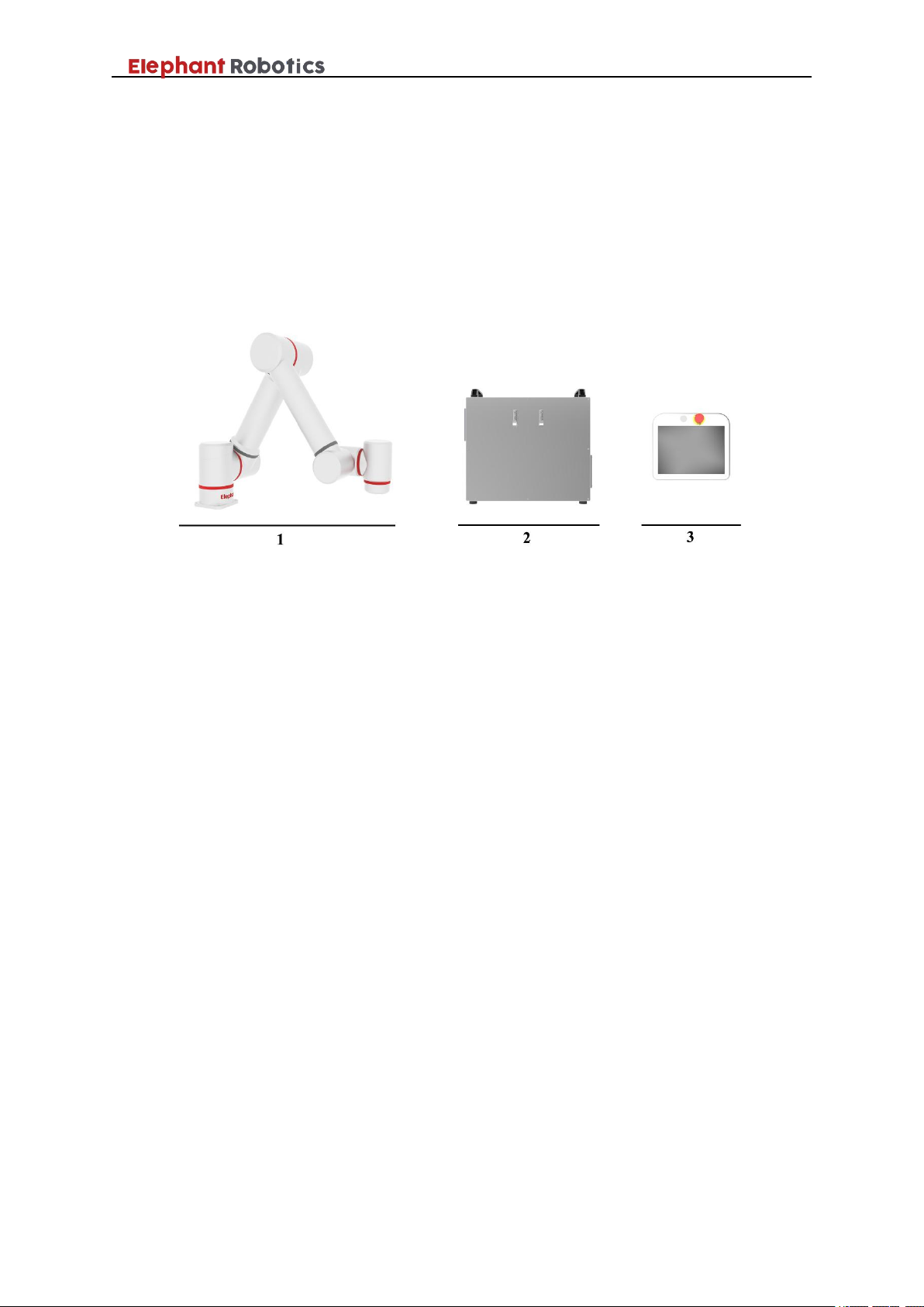
1-The robot
2- Controller
3-Teach pendant
2 About product
2.1 Overview to the robot system
As shown in Figure 2-1, in the Panda series of robots, each robot system
consists of three main components: the robot body (also known as the
manipulator), the controller and the teach pendant.
Figure 2- 1 Robot system
The robot body is a mechanical body used to complete various tasks of the
robot system, and mainly includes a robot casing, a driving device, a
transmission unit, and an internal sensor.
Compared with the heavy and multi-core cables of traditional industrial
robots, the Panda series robot’s drive and brakes are integrated into the robot
body. This greatly reduces the number of cable cores connected from the body
to the controller, and also improves the stability and anti-interference ability of
the cable transmission data, and reduces the cost.
The main material of the body casing is aluminum alloy. The robot's
principle of motion is a combination of rotational motions of six joints. Using
kinematics and dynamics analysis, the algorithm is solved to achieve the desired
motion at the end of the robot.
The controller is the structural realization of the robot control function and
is a key part of determining the function and level of the robot. The controller is
loaded with a power source, a computer, etc., to control the overall motion of
the robot.
The teach pendant is the main interface of human-computer interaction,
and its internal part is composed of a touch screen display, a control circuit
board and some components. The robot can be programmed and operated by
Page 15

Shenzhen Elephant Robotics Technology Co., Ltd.
12
using a teach pendant.
Simply, if the robot system is like a human, then the controller is like a
human brain, controlling the robot body (like a human hand) to perform tasks,
and the teach pendant is the human-machine interface that the robot system
communicates with people.
2.2 Robot
2.2.1 Characteristics of the robot
The Panda series robot have the advantages of short deployment time, easy
operation, safe use and convenient expansion of peripheral equipment, which
can greatly shorten the deployment time of the factory for automation project
transformation and reduce the total cost of deployment. The specific description
is as follows:
1,Easy to deploy
In order to shorten the transformation cost and deployment time of the
automated production line, the Elephant Robotics's products are mainly oriented
to the upgrade and transformation of independent stations compared to the
traditional robotic deployment of the entire automated production line. The
customer or system integrator can choose the adapted end effector, radar or
camera to match the robot.
2,Easy operation
Panda OS and our automated solutions help engineers design a standalone workstation as soon as possible to install end-executing systems, stands,
cameras and other equipment. And dragging the teach function can help users
shorten the teaching time and simplify the debugging steps.
3,Easy to program
Panda OS provides users with graphical programming capabilities to help
users get up and running quickly, even without a programming foundation.
4,Safe and reliable
In addition to the common safety collision detection, Panda series
cooperative robots can also be equipped with safety equipment such as safety
vision, laser radar and grating to ensure a stable and reliable safe working
environment.
2.2.2 Model
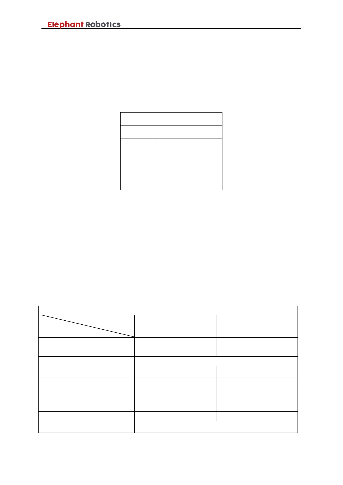
There are two robots in the Panda series, namely Panda 3 and Panda 5. The
model name is shown in Table 2-1.
Page 16
Shenzhen Elephant Robotics Technology Co., Ltd.
13
Panda
3/5
Panda series
Load capacity 3kg/5kg
Table 2- 1 Model description table
2.2.3 Robot joint introduction
The Panda 3 Collaboration Robot is a robot with a load of 3kg and a range
of 550mm. The Panda 5 Collaboration Robot is a robot with a load of 5kg and a
range of 850mm. Their repeat positioning accuracy is ±0.05mm. These two
robots are used in independent work: for loading, unloading, testing, testing and
packaging. They can work safely with workers.
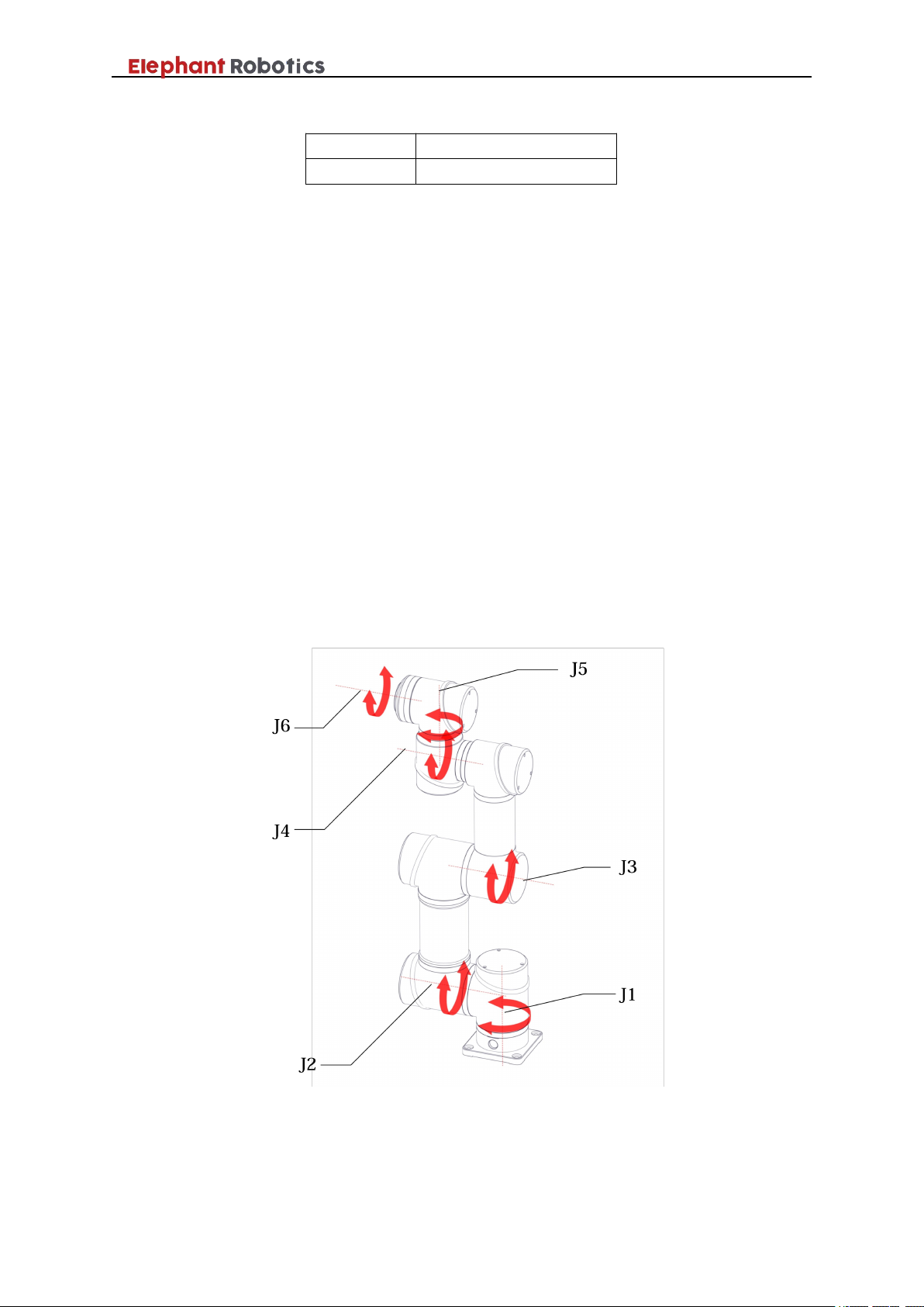
The schematic diagram of the robot body is shown in Figure 2-2.
The mechanical body of the Panda series robot can be thought of as an
open-chain multi-link mechanism. The start link is the base of the robot, the end
link is connected to the end effector, and the adjacent links are connected by a
joint. The Panda series robot is a 6-degree-of-freedom industrial robot
consisting of 6 links and 6 joints (axes). When numbered, the base is called the
link 0 and is not included in the six links. The link 1 is connected to the base by
the joint 1, the link 2 is connected to the link 1 through the joint 2, and so on.
gripper or a pneumatic suction cup.
Figure 2- 2 Schematic diagram of the robot
The flange can be used to connect an end effector, such as an electric
Page 17
Shenzhen Elephant Robotics Technology Co., Ltd.
14
J1
±360°
J2
±360°
J3
±
360
°
J4
±360°
J5
±360°
J6
±360°
Robot
Robot version
Panda 3
Panda 5
Parameter name
Payload
3kg
5kg
Reach
550mm
850mm
Degrees of freedom
6
Working range
±
360
°
±
360
°
Axis maximum speed
J1/J2/J3:180°/sec
J1/J2/J3:150°/sec
J4/J5/J6:208°/sec
J4/J5/J6:208°/sec
Tool speed
1m/sec
1m/sec
Weight
17kg
24.5kg
Position repeatability
±0.05mm
2.3 Scope of work
Table 2-2 shows the joint range data table for the Panda series robot.
Please limit the actual range of the robot according to the range of motion of the
robot before using the robot to avoid the consequences of insufficient arm
length or collision.
Table 2- 2 Joint range data table
2.4 Active load
The Panda 3 robot is rated at 3kg and can operate under loads of 3kg and
below. The Panda 5 robot is rated at 5kg and can operate under loads of 5kg and
below. As the load moves further and further away from the J6 flange position,
its payload will become smaller and smaller.
2.5 Technical Parameter Table
The specifications parameters of the Panda series robot are shown in Table
2-3.
Table 2- 3 Technical Parameter
Page 18

Shenzhen Elephant Robotics Technology Co., Ltd.
15
Dimensions robot base
123mm×123mm
Programming mode
Graphical programming
IP classification
IP54
Typical power consumption
160W
260W
Materials
Aluminium alloy, Rubber
Operating temperature range
0-50℃
Collaboration operation
Test in accordance with:
EN ISO 13848:2008 PL d
EN ISO 10218-1: 2011-Clause 5.4.3
Noise
<70dB
Robot mounting
Any angle
Relative humidity
5%-95%
Controller
Size(L×W×H
)
545mm×285mm×433mm
Weight
25kg
Power supply
AC 110-240V,50-60Hz
IP classification
IP40
Certificate
CE certificate
Interface and openness
SDK(Python, C++,JAVA),API,ROS
I/O ports
Digital Input:16
Digital Ouput:16
I/O power supply
24V 2A
Communication
TCP/IP
Teach Pendant
Size(L×W×H
)
255mm×230mm×90mm
Weight
1.8kg
Screen resolution
1024×768
IP classification
IP20
Screen size
10.4ʺ
Page 19
Shenzhen Elephant Robotics Technology Co., Ltd.
16
Avoid applying external force to the robot's body and motor.
When transporting the robot over long distances, it is necessary to fix it to the
handling device to prevent the robot from tipping over. If necessary, use the
packaging at the time of delivery.
If the robot produces condensation during transportation/storage, turn the power on
after removing condensation.
Please use heavy lifting equipment such as driving as much as possible, and be
careful of the people standing around to prevent the machine from rolling over.
When carrying the Panda 3 or Panda 5 robot manually, the number of personnel
must not be less than two.
The robot is a precision device, so avoid excessive vibration and shock when
handling.
The weight of the Panda 3 robot body is 17 kg. The weight of the Panda 5 robot
body is 24.5 kg.
If the sling is used to lift the robot, in order to avoid the appearance damage of the
robot, place a thick cloth in the place where the sling is in direct contact, and try to
avoid the person standing under the robot body being lifted.
The robot cable and power must be disconnected before handling.
3 Environment and installation
3.1 Transportation and storage
Since the robot is a precision device, please pay special attention to the
protection of the device during transportation.
When transporting before installation, in principle, lifting equipment such
as bridge crane should be used. Since the mass of the main body is not heavy,
manual handling can also be considered without lifting equipment. Pay attention
to safety when handling by hand, and take it with care to avoid damage to the
equipment.
The storage environment temperature of the robot is +0°~+50°, and a
special person shall be responsible for keeping it.
3.2 Open box examination
When the packing box is in place, please confirm that the robot package is
intact. If there is any damage, please contact the logistics company and our
company in time.
After unpacking, check the actual items in the box according to the list of
Page 20

Shenzhen Elephant Robotics Technology Co., Ltd.
17
Temperature
0℃~+50℃
Relative humidity
20%~70%
Indoor and outdoor
requirements
Indoor
Other environmental
requirements
- Avoid sun exposure.
- Keep away from dust, oil smoke, salt, iron filings, etc..
- Keep away from flammable, corrosive liquids and gases.
- Do not come into contact with water.
- Do not transmit shocks, vibrations, etc.
- Keep away from sources of strong electromagnetic
interference.
items.
3.3 Working environment and conditions
Please set up the robot system in the environment that meets the
requirements stated in table 3-1, in order to play / maintain the performance of
the machine and use it safely.
Table 3- 1 Working environment and conditions
3.4 Installation
3.4.1 Installation requirements
The actual weight of the Panda 3 robot is 17kg. The actual weight of the
Panda 5 robot is 24.5kg. Considering the movement of the robot, the center of
gravity will move as the robot moves. Therefore, the robot needs to be fixed on
a solid base to be used normally. Base weight requirements: fixed base, or
mobile base.
The installation angles of the robot include vertical, inverted, side
mounted angles, etc.
Table 3-1 shows the installation environment.
The installation position must not be less than the working range of the
robot.
3.4.2 Installation
1,Interface size of robot base
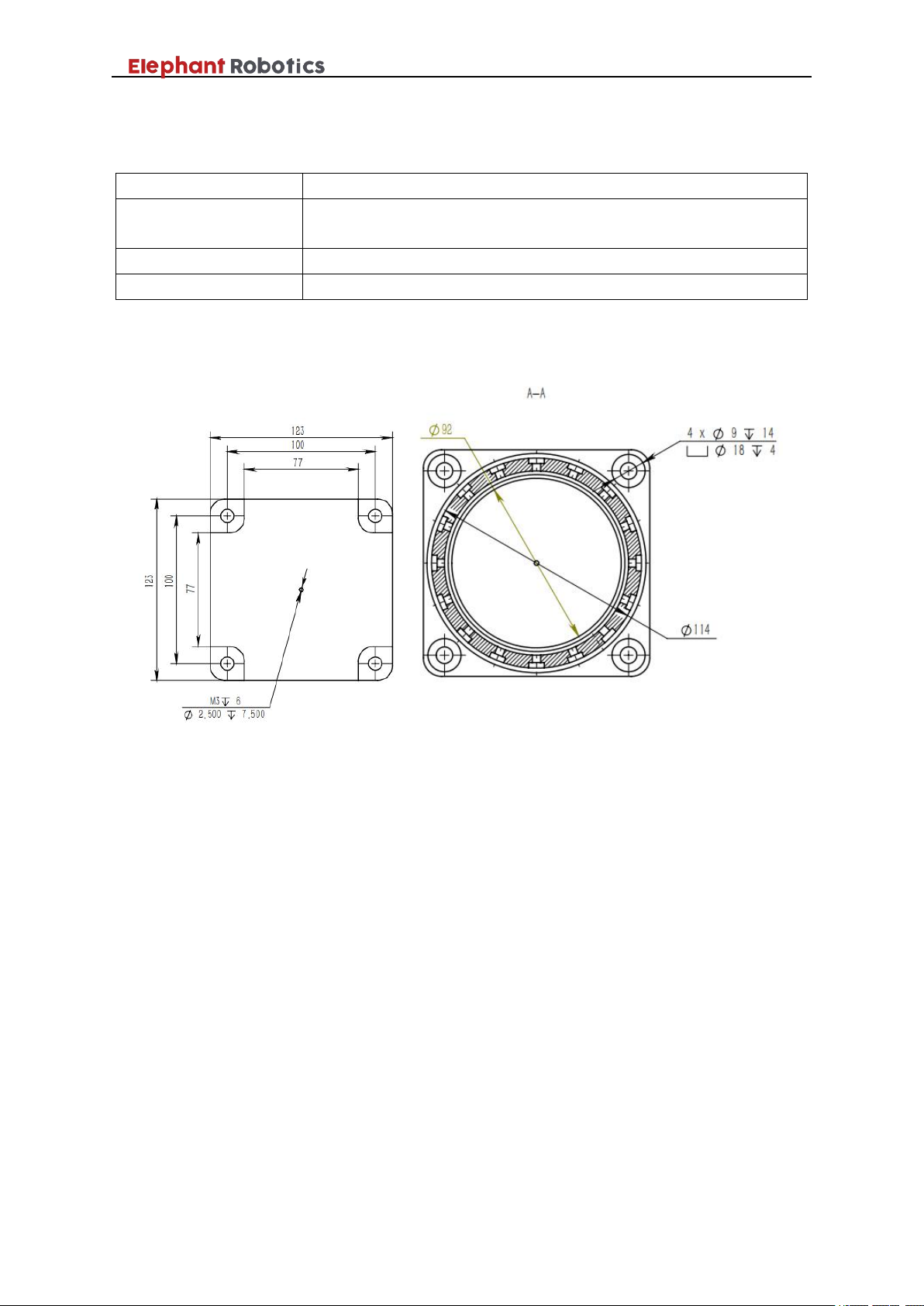
The pedestal fixing hole is the interface that fixes the robot to other bases
or planes. The specific hole size is shown in Figure 3-2. It is 4 through holes
with a diameter of 9 mm, which can be fixed with M8 bolts (M8 bolts and
matching gaskets and nuts are installed in the package).
Page 21
Shenzhen Elephant Robotics Technology Co., Ltd.
18
Bolt specification
M8
Bolt length
Select based on the thickness of the platform of the base
mounting robot
Strength
12.9
Tightening torque
28Nm (recommended using a torque wrench for fastening)
Table 3- 2 Specifications of robot base fixing screw
The specific hole size is shown in Figure 3-1. Make sure that there is a
corresponding threaded hole on the fixed base before installing.
Figure 3- 1 The specific hole size
2, Mount the robot on the base
Before you officially install, please confirm:
The environment to be installed complies with the requirements of
Table 3-1.
The installation position is not less than the working range of the robot,
and there is enough space for installation, use, maintenance and repair.
Place the stand in the proper position.
Installation related tools are ready, such as screws, wrenches, etc.
After confirming the above, move the robot to the mounting surface of the
base, adjust the position of the robot, and align the fixing hole of the robot base
with the hole on the mounting surface of the base.
Page 22
Shenzhen Elephant Robotics Technology Co., Ltd.
19
When adjusting the position of the robot on the mounting base, please avoid
pushing the robot directly on the mounting surface of the base to avoid scratches.
When manually moving the robot, please try to avoid applying external force to
the weak part of the robot body to avoid unnecessary damage to the robot.
As long as the robot is not yet firmly mounted on the base, the robot may be in
danger of falling over. Please keep the balance of the robot.
After aligning the holes, align the screws with the holes and tighten.
3,Place controller, teach pendant
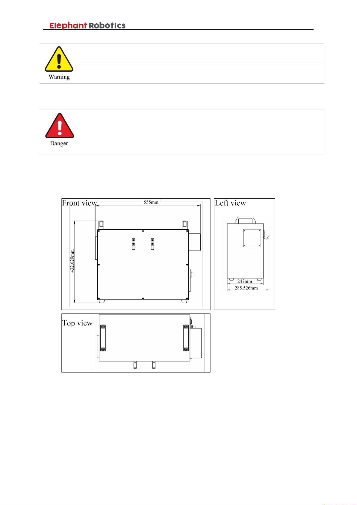
The outline of the controller as shown in Figure 3-2.
Figure 3- 2 Controller dimensions
Please determine the placement position according to the actual size of the
controller. Note that there should be no items to block the cooling fan of the
controller, so as not to affect the heat dissipation effect. A better heat dissipation
effect is beneficial to improve the working life of the controller.
There are four foot cups in the base of the robot controller for smooth
placement of the controller. For the position of the specific cup, please refer to
Page 23
Shenzhen Elephant Robotics Technology Co., Ltd.
20
When placing the robot controller, be careful not to keep its distance from the
robot body beyond the length of the connecting cable.
Choose the placement position of the controller, try to avoid possible problems
such as the controller being bumped or close to the wall not conducive to heat
dissipation.
the following figure. Please place the controller smoothly to prevent the
machine from tilting and injuring people or objects.
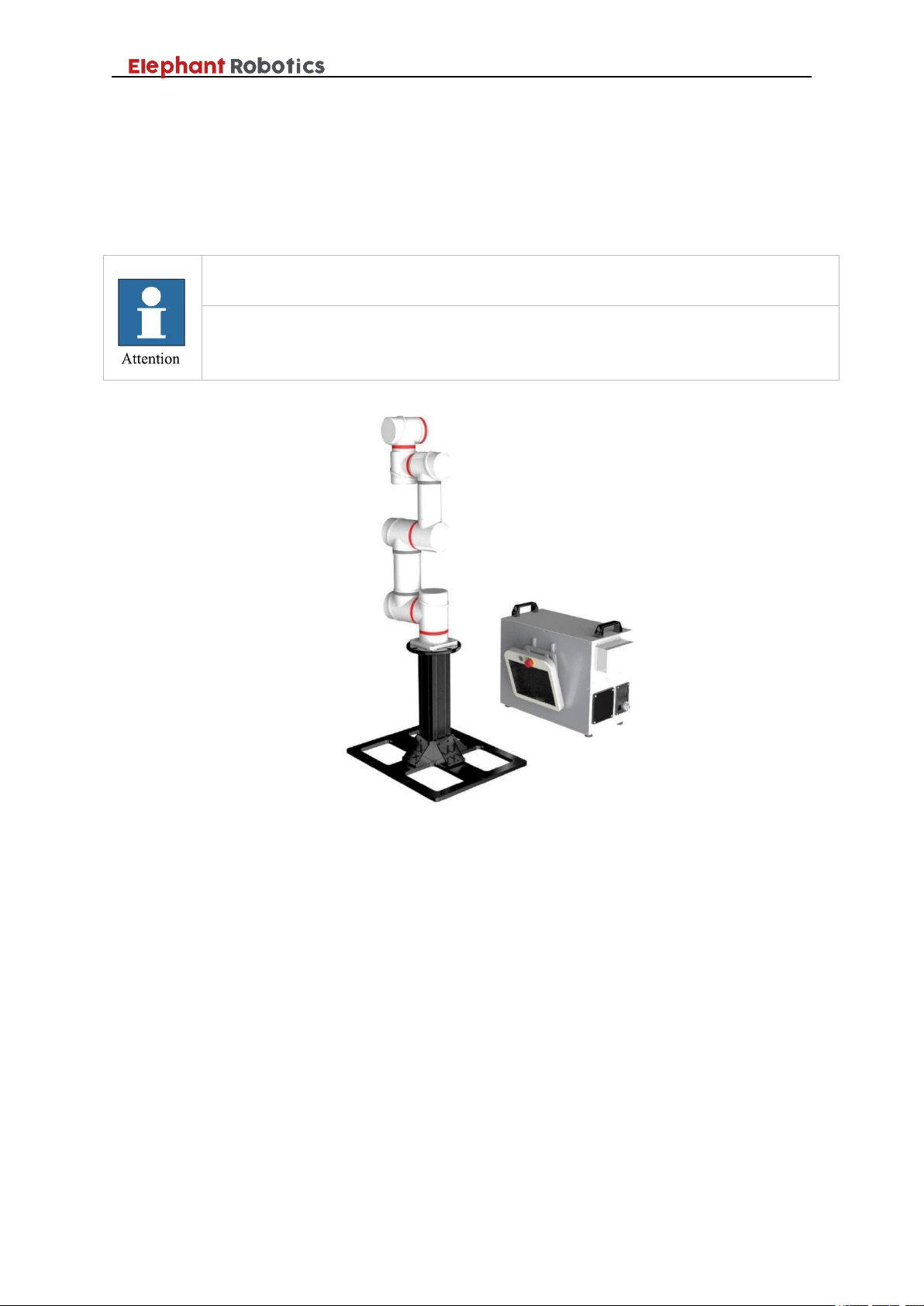
The teach pendant can be hung on the side of the robot controller or placed
on top of the controller.
Figure 3- 3 Installation diagram
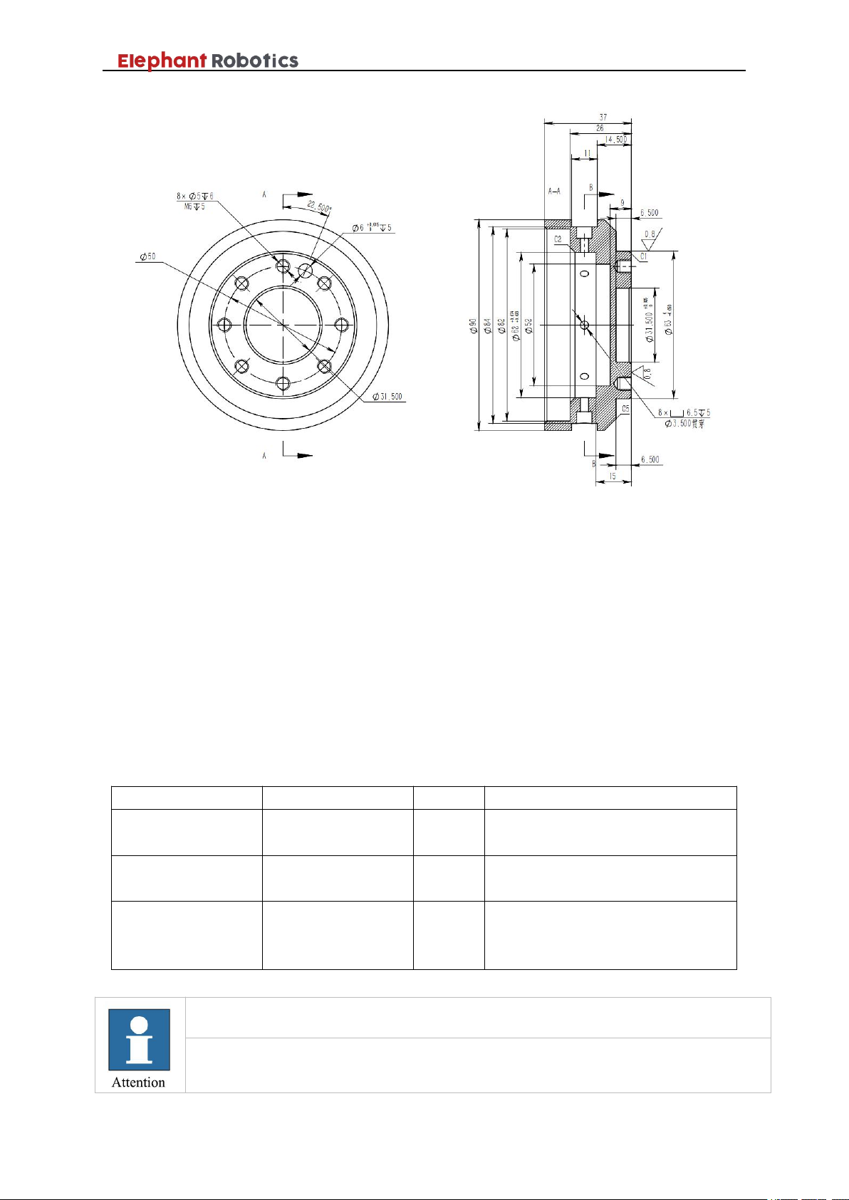
4,Install the end effector to the robot flange
The end effector is a device specially designed and installed at the
mechanical interface for the robot to perform its tasks. For example, grippers,
wrenches, welding torches, spray guns, etc.. The specific flange size is shown in
Figure 3-4.
Page 24
Shenzhen Elephant Robotics Technology Co., Ltd.
21
Type
Connection
Length
Use description
Controller power
cord
External power
supply - controller
2m
Power supply to the entire robot
system.
Teach pendant
Controller - teach
pendant
4m
Provide controller-demonstration
information exchange channels.
Controller-Robot
Connection Cable
Controller-robot
4m
Mainly to drive the robot motor,
collect and analyze the encoder
information.
The original cable must be used.
The cable interface is generally easy to damage. Do not use brute force or
vigorously shake when plugging or unplugging. It is easy to cause the interface to
Figure 3- 4 Flange size
To install the end effector to the robot flange, there are two cases. One is
that the end effector interface corresponds to the flange mechanical interface
size; the other is to use the adapter that meets the size requirements of the
connection interface for connection.
3.5 Electrical connections
3.5.1 Cable connection
There are three cable lines used in the robot system. The specific
information is shown in Table 3-3.
Table 3- 3 Main cables of the robot
Page 25
Shenzhen Elephant Robotics Technology Co., Ltd.
22
loose or deform. Please insert and remove it carefully after alignment.
Be sure to make replacement after turning off the power to the controller and
related equipment and unplugging the power cord. If the work is performed while
the power is on, it may cause electric shock or malfunction.
Be sure to connect the AC power cable to the power plug. Do not connect directly
to the factory power supply. Turn off the power to the robot system by unplugging
the power cord. It is extremely dangerous to work when the AC power cable is
connected to the factory power supply, which may result in electric shock and
malfunction of the robot system.
Be careful not to bend the cable forcibly to avoid applying a load to the cable.
Also, do not place heavy objects on the cable and forcibly bend or pull the cable.
Failure to do so may result in damage to the cable, disconnection, or poor contact,
electric shock or improper system operation.
Before wiring, turn off the power of the controller and related devices and pull up
the warning sign (eg, do not turn on the power). Wiring under power-on conditions
is extremely dangerous and may result in electric shock and malfunction of the
robot system.
Please ensure that the ground wire connection is reliable, otherwise it may cause
fire or electric shock.
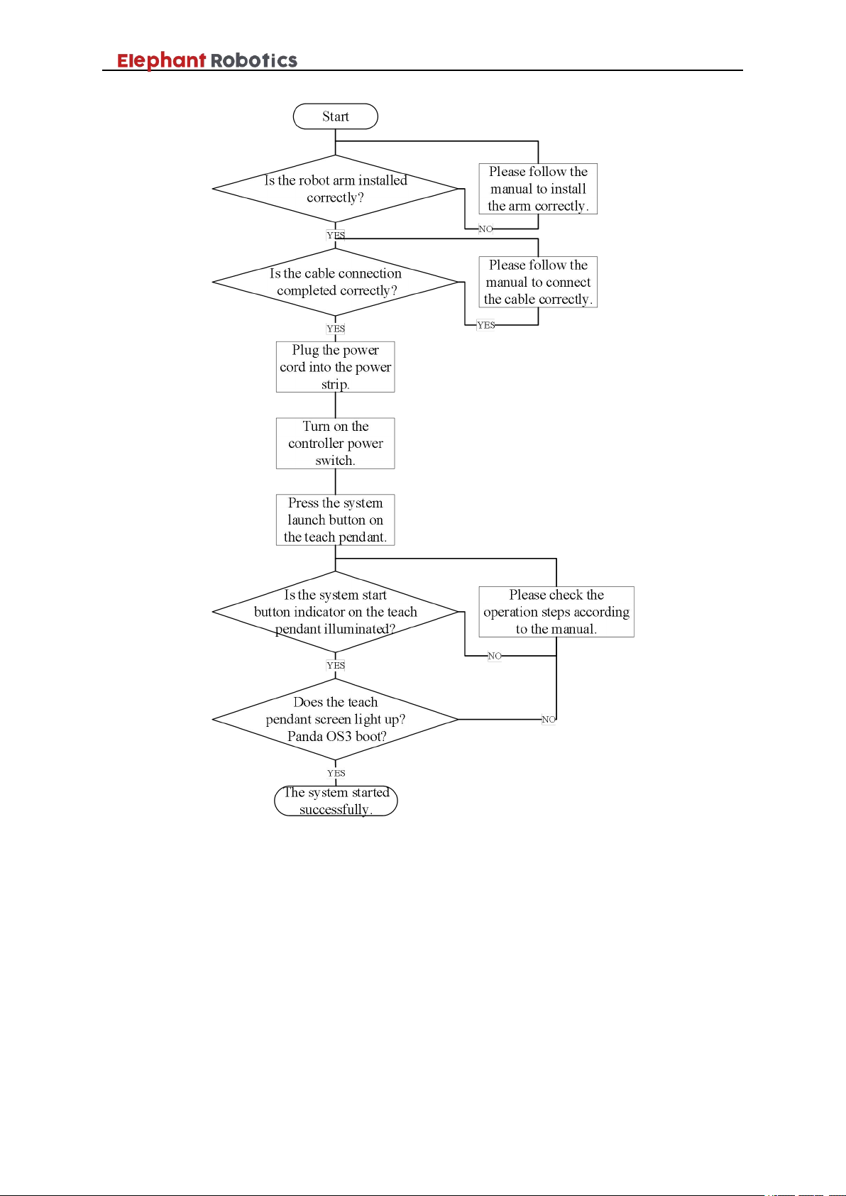
3.6 System startup debugging
After the installation and connection work is completed, user need to plug
in the power cord, turn on the power switch, press the system start button of the
teach pendant. After that, user should observe whether the display button of the
teach pendant is lit. If the light is on, it means the installation is successful, you
can go to the next step. Otherwise user need to check if an important step is
missing. If it is unsuccessful according to the manual, it may cause a
malfunction during transportation. Do not disassemble the parts by yourself.
Please contact a professional for disposal.
Robot system boot flow chart as shown in Figure 3-5. Please strictly follow
the manual, otherwise the warranty will not be available if the robot is damaged
due to improper operation.
Page 26
Shenzhen Elephant Robotics Technology Co., Ltd.
23
Figure 3- 5 Robot system boot flow chart
3.7 IO Board
3.7.1 IO board introduction
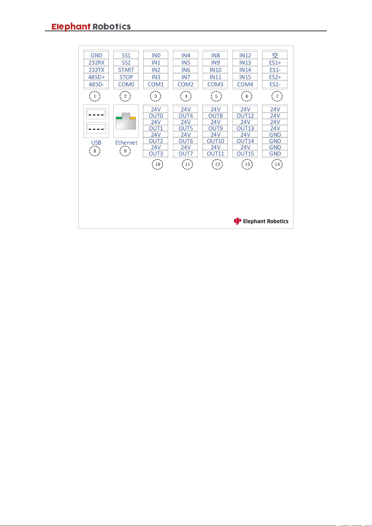
Figure 3-6 shows the IO board port of the Panda series robot. Port details
are shown in Tables 3-4~8.
Page 27
Shenzhen Elephant Robotics Technology Co., Ltd.
24
1- Serial port
2- External control
port
3- Digital input 0~3
4- Digital input 4~7
5- Digital input 8~11
6- Digital input
12~15
7- External E-STOP port
8-USB port
9- Ethernet interface
10- Digital output
0~3
11- Digital output 4~7
12- Digital output
8~11
13- Digital output
12~15
14- DC power port
Figure 3- 6 IO board port description
The Panda series robot provides common communication interfaces, power
interfaces, general purpose IO ports, and dedicated IO ports. Among them, the
universal IO port includes 16 digital input signals and 16 digital output signals
for interaction with other devices, and together with other devices constitute an
important part of the automation system.
For example, the user can use the digital output signal to control the
electric jaws installed on the output flange, or connect to the PLC for signal
interaction.
1,Communication port
As shown in Table 3-4, the IO board provides three communication
methods, namely serial communication, USB communication, and Ethernet
network port communication.
Page 28

Shenzhen Elephant Robotics Technology Co., Ltd.
25
No.
Type
Port
Definition
Description
1
Serial port
0
GND
Signal ground(RS232)
1
232RX
Receive data(RS232
)
2
232TX
Send data(RS232
)
3
485D+
Receive data(RS485)
4
485D-
Send data(RS485
)
8
USB port
-
USB1
USB port 1
-
USB2
USB port 2
9
Ethernet interface
-
Ethernet
Ethernet interface
Table 3- 4 IO port description table 1(Communication port)
1) Serial communication: The serial port sends and receives bytes in bits.
It’s simple and able to communicate over long distances.
In this IO board, serial communication is divided into RS232 and RS485.
The former occupies the first three ports of the terminal block, and the latter
occupies the last two ports. RS232 is full-duplex, the serial port can receive data
while using one line to send data while using another line. RS485 is half-duplex,
and only one point can be sent at any time. Therefore, the transmitting circuit
must be controlled by an enable signal.
RS485 and RS232 are only differences in the physical protocol of
communication (interface standard) . RS485 adopts differential transmission
mode, and RS232 is single-ended transmission mode. But the communication
program doesn't have much difference.
Users can choose one according to actual needs.
2) USB port
Users can use the USB interface to copy program files, or use the USB
interface to connect peripherals such as mice and keyboards.
3) Ethernet interface
Users can use the Ethernet interface for communication between the PC
and the robot system, or for Ethernet communication with other devices.
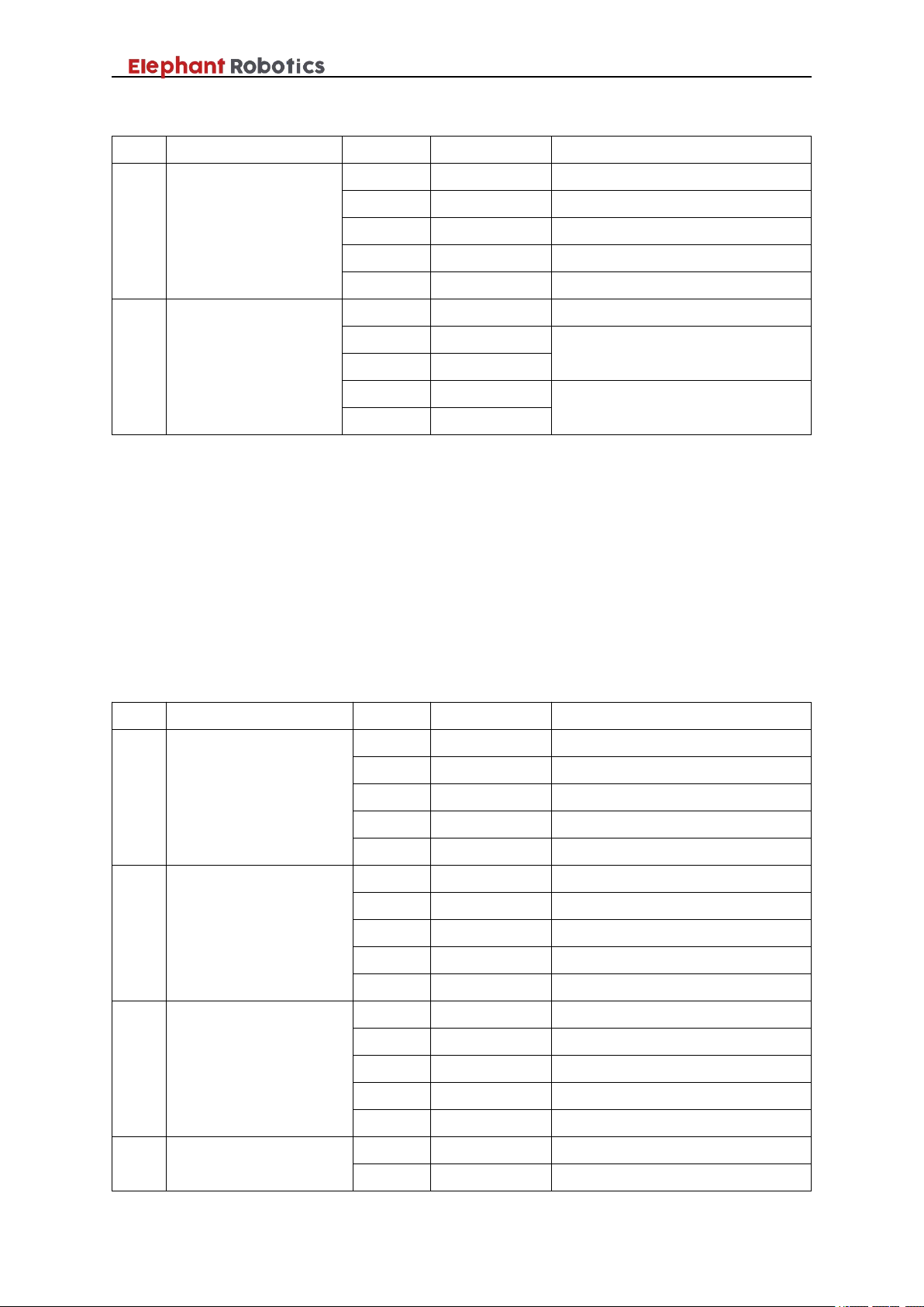
2,Control signal port
As shown in Table 3-5, the IO board provides the control signal port.
Page 29
Shenzhen Elephant Robotics Technology Co., Ltd.
26
No.
Type
Port
Definition
Description
2
External control port
0
SS1
Emergency stop control signal 1
1
SS2
Emergency stop control signal 2
2
START
START
3
STOP
STOP
4
COM0
Common port 0
7
External emergency
stop port
0
Null
Undefined
1
ES1+
External emergency stop control
signal 1
2
ES1-
3
ES2+
External emergency stop control
signal 2
4
ES2-
No.
Type
Port
Definition
Description
3
Digital input port
0~3
0
IN0
Digital input signal 0
1
IN1
Digital input signal 1
2
IN2
Digital input signal 2
3
IN3
Digital input signal 3
4
COM 1
Common port 1
4
Digital input port
4~7
0
IN4
Digital input signal 4
1
IN5
Digital input signal 5
2
IN6
Digital input signal 6
3
IN7
Digital input signal 7
4
COM 2
Common port 2
5
Digital input port
8~11
0
IN8
Digital input signal 8
1
IN9
Digital input signal 9
2
IN10
Digital input signal 10
3
IN11
Digital input signal 11
4
COM 3
Common port 3
6
Digital input port
12~15
0
IN12
Digital input signal 12
1
IN13
Digital input signal 13
Table 3- 5 IO port description table 2(Control signal port)
With these ports, external devices can control the system's emergency stop
loop. It is also possible to control the start and stop of the program. These ports
make it easy for the user to control the robot system as a link in the automatic
control system.
3,Digital input ports
As shown in Table 3-6, there are general-purpose digital input ports. The
Panda series robot provides 16 digital input signals.
Table 3- 6 IO port description table 3(Digital input ports
)
Page 30

Shenzhen Elephant Robotics Technology Co., Ltd.
27
2
IN14
Digital input signal 14
3
IN15
Digital input signal 15
4
COM 4
Common port 4
No.
Type
Port
Definition
Description
10
Digital output port
0~3
0
24V
DC 24V
1
OUT0
Digital output signal 0
2
24V
DC 24V
3
OUT1
Digital output signal 1
4
24V
DC 24V
5
OUT2
Digital output signal 2
6
24V
DC 24V
7
OUT3
Digital output signal 3
11
Digital output port
4~7
0
24V
DC 24V
1
OUT4
Digital output signal 4
2
24V
DC 24V
3
OUT5
Digital output signal 5
4
24V
DC 24V
5
OUT6
Digital output signal 6
6
24V
DC 24V
7
OUT7
Digital output signal 7
12
Digital output port
8~11
0
24V
DC 24V
1
OUT8
Digital output signal 8
2
24V
DC 24V
3
OUT9
Digital output signal 9
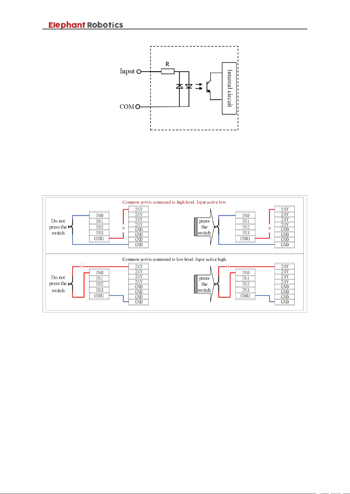
It should be noted that the input common terminal needs to be connected to
the DC 24V power supply. The input port can be active high or active low
depending on the common configuration.
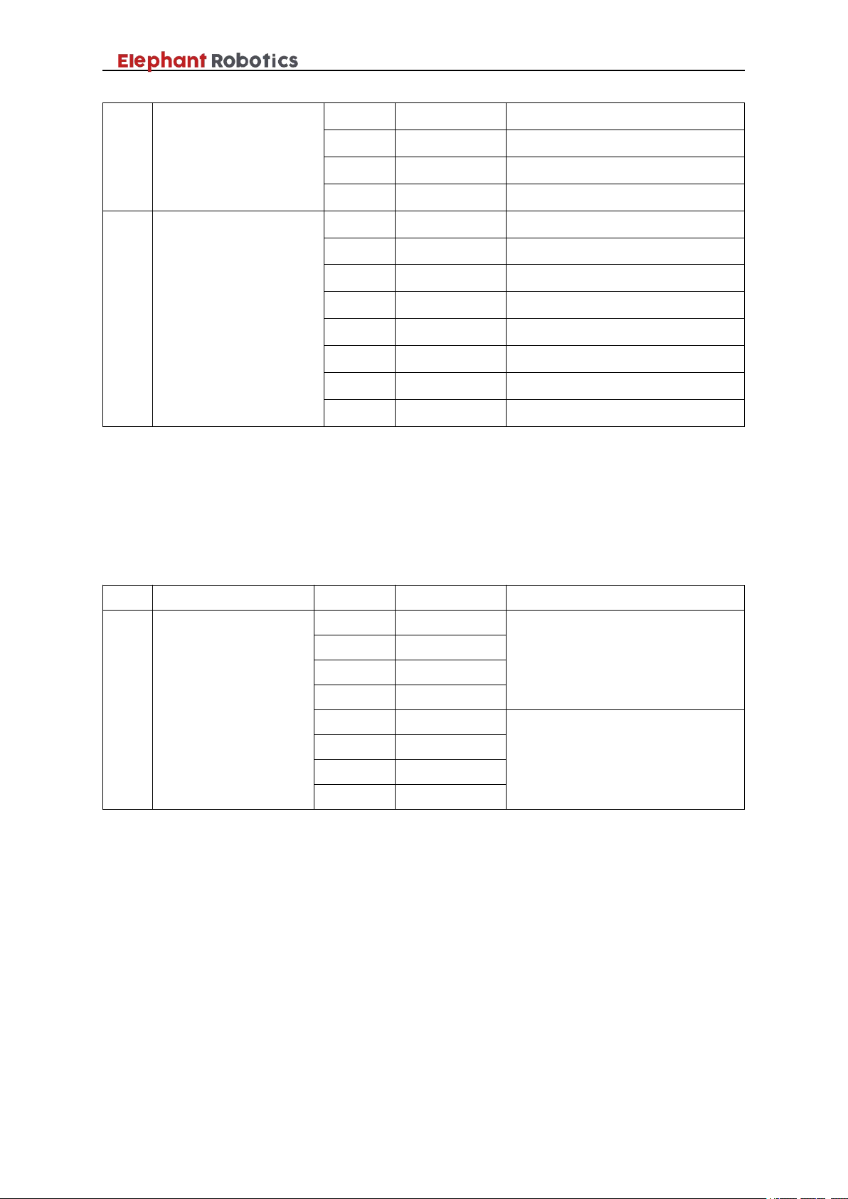
4,Digital output ports
As shown in Table 3-7, there are general-purpose digital output ports. The
Panda series robot provides 16 digital output signals.
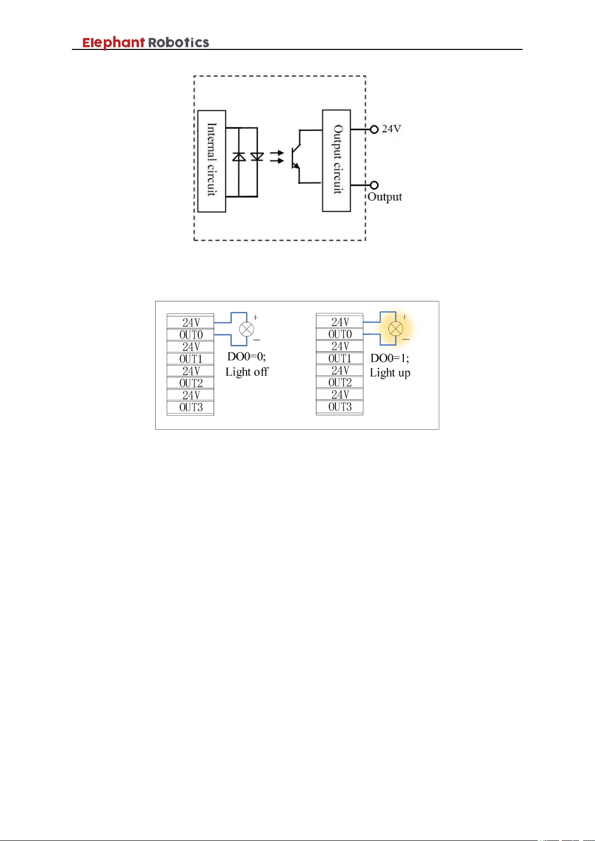
Unlike the input port, the internal DC 24V provides 24V directly. The
output is valid at 0V. The peripherals form a complete loop by connecting the
two ends (output signal and common port), and the peripherals can be
controlled by controlling the state of the outputs.
Table 3- 7 IO port description table 4(Digital output ports)
Page 31
Shenzhen Elephant Robotics Technology Co., Ltd.
28
4
24V
DC 24V
5
OUT10
Digital output signal 10
6
24V
DC 24V
7
OUT11
Digital output signal 11
13
Digital output port
12~15
0
24V
DC 24V
1
OUT12
Digital output signal 12
2
24V
DC 24V
3
OUT13
Digital output signal 13
4
24V
DC 24V
5
OUT14
Digital output signal 14
6
24V
DC 24V
7
OUT15
Digital output signal 15
No.
Type
Port
Definition
Description
14
DC power port
0
24V
Internal DC power supply 24V
1
24V
2
24V
3
24V
4
GND
Internal DC power supply GND
5
GND
6
GND
7
GND
5,DC power port
As shown in Table 3-8, the IO board provides an internal DC 24V for the
user to use.
Table 3- 8 IO port description table 5(DC power port
)
3.7.2 IO port principle and application
1,Digital input port
As shown in Figure 3-7, the input signal is driven through the currentlimiting resistor R to allow the internal circuit to detect it. The difference
between the PNP input and the NPN input is that one end of the PNP input is
connected to 0V, and one end of the NPN input is connected to 24V.
Page 32
Shenzhen Elephant Robotics Technology Co., Ltd.
29
Figure 3- 7 Digital input port schematic
Figure 3-8 shows an example of an input connection application. When the
common port is connected to 24V, once an external device inputs 0V, the input
signal is in the High state, otherwise it is in the Low state. vice versa.
Figure 3- 8 Input application example diagram
2,Digital output port
As shown in Figure 3-9, the output is an NPN output. When the control
signal is high, the triode is activated and the output is connected to GND. When
the control signal is low, the triode is blocked and the output is in a floating
state.
Page 33
Shenzhen Elephant Robotics Technology Co., Ltd.
30
Figure 3- 9 Digital output port schematic
Figure 3-10 shows an example of an output connection application.
Figure 3- 10 Output application example diagram
Page 34

Shenzhen Elephant Robotics Technology Co., Ltd.
31
4 Calibration
If the parts of the robot (motor, reducer, timing belt, etc.) are replaced,
there will be a deviation between the origin stored by each motor encoder and
the origin stored by the controller, and the correct positioning cannot be
performed. The origin is the reference of the robot coordinate system. Without
the origin, the robot cannot judge its position. Therefore, in order to obtain the
highest possible absolute positioning accuracy, the robot must be calibrated (the
operation where the two origin positions are the same is called calibration) .
Robots are specially calibrated before they leave the factory. Generally,
recalibration is required in the following cases:
After replacing the parts of the robot (motor, reducer, timing belt, etc.).
Collision with the work-piece or environment.
Move the robot joints without being under the control of the controller.
Replace the encoder data backup battery.
Other conditions that may cause zero point loss.
Page 35
Shenzhen Elephant Robotics Technology Co., Ltd.
32
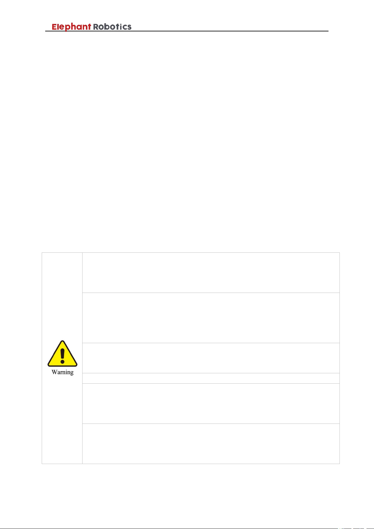
Do not randomly change any information in software security configuration (such
as force limits). If the safety parameters change, the entire robot system should be
considered a new system, which means that all safety audit processes, such as risk
assessment, must be updated.
Do not remove any parts unless otherwise stated in this manual. The maintenance
steps shall be strictly adhered to according to the content. If wrong disassemble or
maintenance is performed, not only will the robot system malfunction, but it may
also cause serious safety problems. In addition, self-disassembly during the
warranty period will lose the warranty qualification.
Be sure to confirm the robot's action after replacing the parts outside the robot's
action area. Otherwise, the robot before the action confirmation may perform
unexpected actions and may cause serious safety problems.
All disassembled robots need to be recalibrated.
If you have not received training, keep away from the robot when the power is on.
Also, do not enter the action area. Even if you see that the robot seems to stop
moving, the robot that is powered on may accidentally operate and may cause
serious safety problems.
Before entering the normal operation, please confirm that the emergency stop
switch and the safety guard switch are in normal operation. If the switch does not
operate normally, the safety function cannot be performed in an emergency, which
may result in serious injury or serious damage, which is very dangerous.
5 Maintenance
5.1 On the safety of maintenance
When the robot has been running for a period of time, it is necessary to
carry out necessary maintenance to ensure that the robot's function is normal.
Be sure to perform robot maintenance by trained personnel.
Personnel trained in safety refer to those that have been regulated by
national laws and regulations.
Personnel who are trained in the safety when engaged in industrial
robot-related business (training on knowledge, operation, teaching, etc.
of industrial robots, knowledge of business operations such as
inspections, and related laws and regulations).
The company's training is for those who have completed the
installation training and maintenance training.
Before maintenance, please read “Safety on Maintenance”, this manual and
related manuals, and perform maintenance based on a thorough understanding
of safety maintenance methods.
Page 36
Shenzhen Elephant Robotics Technology Co., Ltd.
33
Be sure to perform maintenance, replacement, and wiring work after turning off
the power to the controller and related equipment and unplugging the power cord.
Failure to do so may result in electric shock or malfunction.
No.
Contents
Equipment
Routine
1
month
3
months
6
months
12 months
1
Inspection
Robot appearance
√
2
Cable interface
√
3
Motor, reducer
√
4
Cable
harnes
s
external
√
5
internal
√
6
Screw
surface
√
7
internal
√
8
Clean
Whole robot
√
9
Replaceme
nt
Lubricating oil
Replace when the gear unit needs to be replaced.
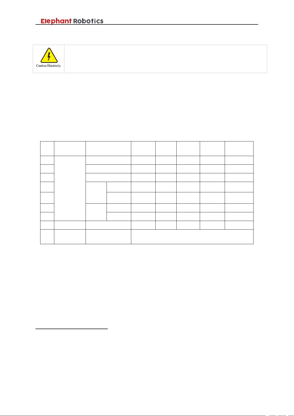
5.2 Maintenance plan
In order for the robot to maintain efficient performance over the long term,
regular maintenance is required. The maintenance personnel must prepare an
overhaul plan and strictly implement it. The maintenance plan for the Panda
series robot is shown in Table 5-1.
Table 5- 1 Maintenance schedule
5.3 Who to contact
1, System integrator
You can directly contact the system integrator responsible for installing
and commissioning the Panda series robot.
2, Supplier
You can contact the supplier of Elephant Robotics in your region. For
specific supplier information, please visit the official website:
www.elephantrobotics.cn.
3, Official website
You can check out on the official website of the Elephant Robotics
(www.elephantrobotics.cn) for more information.
Page 37

Shenzhen Elephant Robotics Technology Co., Ltd.
34
6 Repair
When the robot malfunctions, do not continue to operate. Please
immediately contact the operator who has received the prescribed training to
perform fault analysis, so as to clearly grasp the phenomenon and determine
what components are abnormal.
Matters on repair, inspection, adjustment, etc. of the robot must be carried
out by an authorized system integrator or agent. Please contact a professional
for disposal. Do not disassemble the robot at will. See section 5.3 for contact
details.
When contacting, please prepare the following items in advance:
Controller name, serial number.
Robot name, serial number.
Description of problem (Preferably with pictures, log information etc.).
 Loading...