

Page 1

STEALTH® v2
www.shsglobal.store
User’s Guide
Page 2

STEALTH® v2 User’s Guide
www.shsglobal.store
Rev. 1.05, June, 2008
Part #117-0150
Copyright © Element Labs, Inc.
The Element Labs logo and STEALTH® are trademarks of Element Labs, Inc.
Other trademarks and trade names may be used in this document to refer to products by other
entities. Element Labs, Inc. claims no proprietary interest in trademarks and trade names owned by
others.
Information and specifications in this document are subject to change without notice. Element
Labs, Inc. assumes no responsibility or liability for any errors or inaccuracies that may appear in this
manual.
Contact Info
Element Labs, Inc.
9701 Metric Boulevard
Suite 200
Austin, TX 78758
United States
tel +1 512 491 9111
fax +1 512 491 9122
Element Labs GmbH
Lindener Str. 15
D-38300 Wolfenbüttel
Germany
tel +49 5331 905660
fax +49 5331 905661
Element Labs Ltd.
19A Perseverance Works
38 Kingsland Road
London E2 8DD
United Kingdom
tel +44 (0) 20 7749 0611
fax +44 (0) 20 7749 0622
http://www.elementlabs.com
[email protected]
STEALTH® v2 User’s Guide
Page 3

T
www.shsglobal.store
ABLE OF CONTENTS
Chapter 1: Introduction 1-1
System Overview ___________________________________________________ 1-2
Chapter 2: Processing Components 2-1
VP1 - Video Processing Unit ___________________________________________ 2-2
Front Panel Description ___________________________________________ 2-2
Rear Panel Description ___________________________________________ 2-3
SP1 – Signal Processing Unit __________________________________________ 2-4
Front Panel Description ___________________________________________ 2-4
Rear Panel Description ___________________________________________ 2-5
Menu Navigation ________________________________________________ 2-5
DD1 – Data Distribution Unit __________________________________________ 2-8
Front Panel Description ___________________________________________ 2-8
Rear Panel Description ___________________________________________ 2-8
PDB-3 – Power and Data Distribution ___________________________________ 2-9
Front Panel Description ___________________________________________ 2-9
Rear Panel Description __________________________________________ 2-10
DSU – Data Supply Unit _____________________________________________ 2-12
Front Panel Description __________________________________________ 2-14
Chapter 3: Rigging and Mechanical 3-1
Overview __________________________________________________________ 3-2
Header Assembly ___________________________________________________ 3-3
Description _____________________________________________________ 3-3
Connecting Multiple Headers ______________________________________ 3-4
STEALTH Panel _____________________________________________________ 3-5
Connecting Multiple STEALTH Panels _______________________________ 3-6
Folding STEALTH Panels __________________________________________ 3-8
Power & Data Connections ________________________________________ 3-9
Appendix A : Specifications A-1
VP1 Specifications __________________________________________________ A-2
SP1 Specifications __________________________________________________ A-3
DD1 Specifications _________________________________________________ A-4
PDB-3 Specifications ________________________________________________ A-5
DSU Specifications _________________________________________________ A-6
STEALTH Panel Specifications ________________________________________ A-7
STEALTH® v2 User’s Guide TOC-1
Page 4

Appendix B : LedGuru Software B-1
www.shsglobal.store
Communication Setup _______________________________________________ B-2
Input Tab __________________________________________________________ B-3
Output Tab ________________________________________________________ B-4
Input Cropping _________________________________________________ B-4
DVI Output _____________________________________________________ B-5
50 / 60 Hz Field Rates ________________________________________ B-5
Frame Rate Conversion _______________________________________ B-6
Picture Scaling __________________________________________________ B-6
Pattern Generator ___________________________________________________ B-7
File Load Save ______________________________________________________ B-8
Appendix C: Application Notes C-1
SP1 Vertical Offset ___________________________________________________ C-2
Index IX-1
STEALTH® v2 User’s Guide TOC-2
Page 5

C HAPTER
www.shsglobal.store
Chapter 1 I
This User’s Guide covers the typical STEALTH system and its various components in
detail and illustrates sample configurations.
Chapters in this manual are divided into the following topics:
• Introduction
• Processing Components
• Rigging and Mechanical
• Specifications
• LedGuru Software
If you are viewing this manual in PDF form, you can click on any link to jump
directly to a referenced topic. Links are identified by the colored, underlined type.
For example, the chapters listed above are links and will take you directly to that
chapter.
The same methodology applies to entries in the Table of Contents although they
are not displayed as links.
, (p. 1-1)
, (p. 2-1)
, (p. 3-1)
, (p. A-1)
, (p. B-1)
NTRODUCTION
STEALTH® v2 User’s Guide 1-1
Page 6

System Overview
www.shsglobal.store
The STEALTH system is a modular LED display product that allows for full motion
video to be displayed on high resolution STEALTH panels.
The STEALTH panels are lightweight and rapidly deployable. A nearly 60 percent
transparent design makes it easy for set pieces or even other display devices to
remain visible behind it allowing for a number of different creative effects.
STEALTH is comprised of the following hardware components:
Chapter 1
Introduction
• VP1 - Video Processing Unit
• SP1 – Signal Processing Unit
• DD1 – Data Distribution Unit
• PDB-3 – Power and Data Distribution
• DSU – Data Supply Unit
• STEALTH Panel
The STEALTH system is capable of handling many types of video signals including:
•DVI
•SD-SDI
• HD-SDI (limited resolution, see page 2-2
• Component
•S-Video
• Composite
The VP1 takes one of the above signals and converts it to the proper format for
input to the SP1. The SP1 requires a 1024x768 Digital Visual Interface (DVI) signal at
60 Hz with high (+) or low (-) vertical sync.
(p. 3-5)
(p. 2-2)
(p. 2-4)
(p. 2-8)
(p. 2-9)
(p. 2-12)
)
NOTE
If you already have a properly formatted DVI signal for the SP1 (1024x768 @ 60 Hz),
you do not need the VP1.
Throughout this manual, screen sizes and/or pixel dimensions are referenced in the
commonly used form of 1024x768. The first number is the horizontal value and the
second number is the vertical value. For example, the DVI input signal to the VP1 is
1024 horizontal pixels by 768 vertical pixels and is represented as 1024x768.
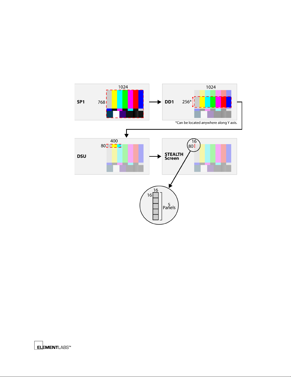
The SP1 has 2 fiber optic outputs each with a resolution of 1024x256 pixels. One or
both SP1 outputs are connected to the DD1. The DD1’s job is to slice up the signal
into 400x80 pixel chunks which are then routed to the individual STEALTH panels
via the PDB-3.
STEALTH® v2 User’s Guide 1-2
Page 7
Chapter 1
www.shsglobal.store
Introduction
The PDB-3 contains 2 DSUs, each with 4 outputs. The DSU handles the final
conversion of the video signal into 16x80 blocks which connect to a column of 5
STEALTH panels. Each STEALTH panel is an individual array of 16x16 pixels.
The following figure illustrates the basic signal flow of the STEALTH system. Unless
otherwise noted, the numbers shown are pixel dimensions.
Figure 1.1
STEALTH System Signal Flow
This is a very simplified explanation of the STEALTH system. The following chapters
will provide you with more detailed information on the STEALTH system.
STEALTH® v2 User’s Guide 1-3
Page 8

C HAPTER
www.shsglobal.store
Chapter 2 P
This chapter provides details on the STEALTH System processing components and
covers the following topics:
• VP1 - Video Processing Unit
• SP1 – Signal Processing Unit
• DD1 – Data Distribution Unit
• PDB-3 – Power and Data Distribution
• DSU – Data Supply Unit
ROCESSING COMPONENTS
(p. 2-2)
(p. 2-4)
(p. 2-8)
(p. 2-9)
(p. 2-12)
STEALTH® v2 User’s Guide 2-1
Page 9
VP1 - Video Processing Unit
www.shsglobal.store
The VP1 is a Video Processing Unit capable of accepting several video formats and
outputting a 1024x768 pixel DVI-D signal. The VP1 is operated via serial control
from a PC using the supplied LedGuru software. Refer to LedGuru Software
for information on controlling the VP1 via the LedGuru Software.
The following is a list of the video signals that the VP1 accepts:
•DVI
•SD-SDI
• HD-SDI (limited resolution, see note below)
• Component
•S-Video
• Composite
Processing Components
Chapter 2
, (p. B-1)
NOTE
If you already have a properly formatted DVI signal for the SP1 (1024x768 @ 60 Hz),
you do not need the VP1.
HD-SDI input video is limited to 720x486 resolution.
Front Panel Description
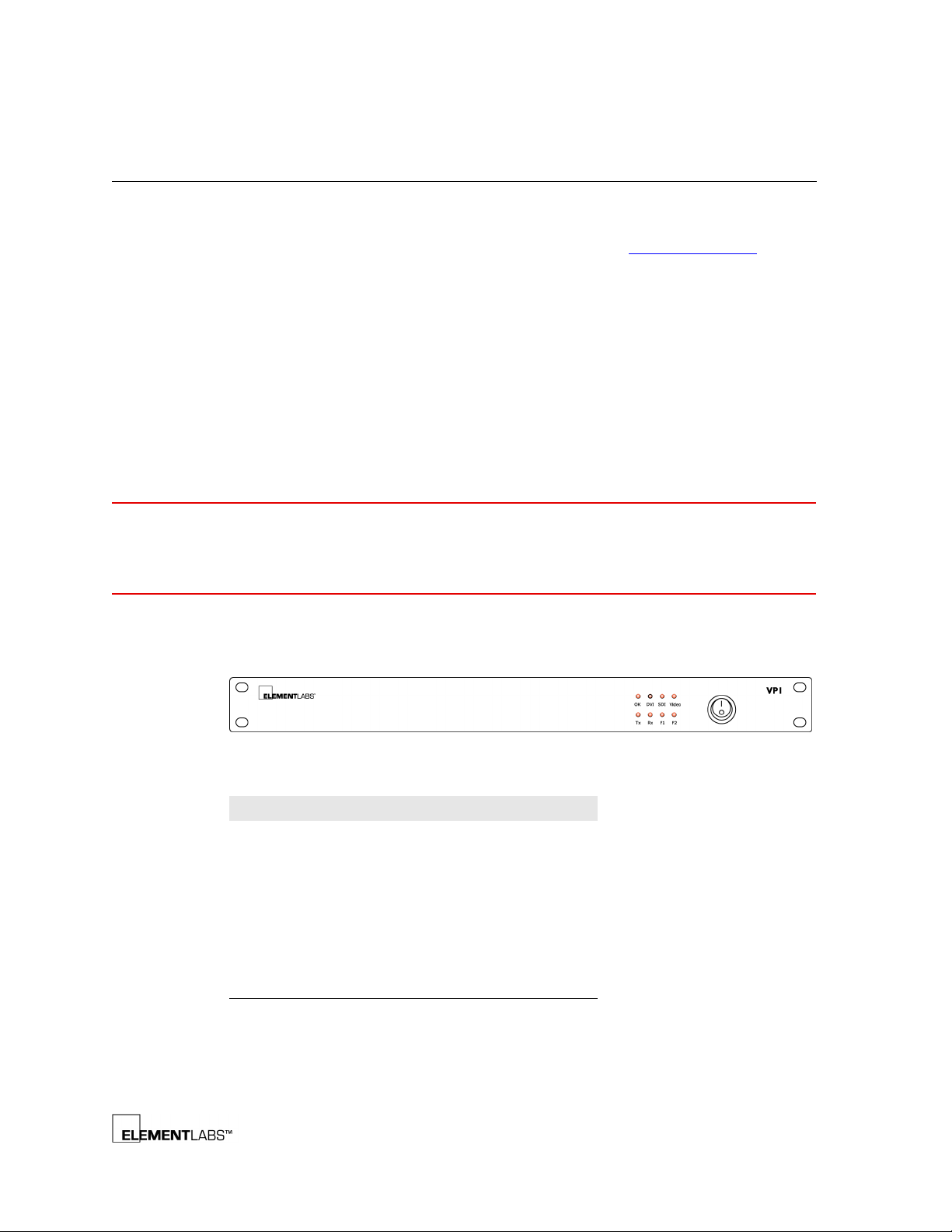
The following information describes the VP1 front panel:
Figure 2.1
LED Name Function
OK Running Normally
DVI Receiving DVI Signal
SDI Receiving SDI Signal
VIDEO Receiving Analog Video Signal
RX Receiving Data
VP1 Front Panel
TX Transferring Data
F1 System Fault
F2 System Fault
STEALTH® v2 User’s Guide 2-2
Page 10
Rear Panel Description
www.shsglobal.store
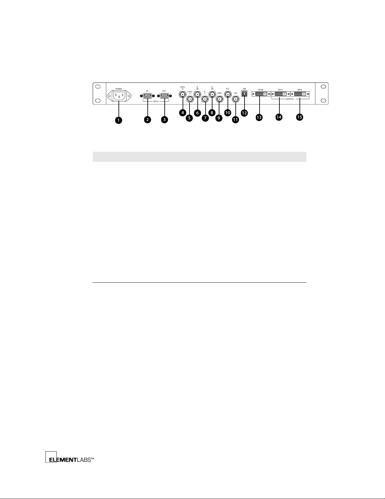
The following information describes the VP1 rear panel:
Processing Components
Chapter 2
Figure 2.2
Legend # Label Info
4,5 CVBS1,CVBS2 Composite Video Signal Input 1 and 2
4,5 Y1/C1 Y/C Video Signal Input 1
6-9 RGBS Red, Green, Blue and Sync (RGBS) Component
6-9 YPrPbS Y, Pr (R-Y), Pb (B-Y) and Sync Component Video
10 YC2 Y/C Video Signal Input 2
11 SDI Serial Digital Interface Input
12 USB USB Port (unused)
13 DVI in DVI Input
14,15 DVI out 2xDVI Outputs (1024x768 @ 60Hz)
VP1 Rear Panel
1 AC Power Input 85~264 VAC, 50/60 Hz
2 RS232 in Serial Control of VP1 from a PC
3 RS232 out RS232 Output Signal Interface (unused)
Video Signal Input
Signal Input
STEALTH® v2 User’s Guide 2-3
Page 11
SP1 – Signal Processing Unit
www.shsglobal.store
The SP1 is the main controller for the STEALTH system. The SP1 receives a DVI input
(1024x768 @ 60 Hz) and processes the image to be displayed on up to two DD1s
(DD1 – Data Distribution Unit
display to change many parameters including the following image controls:
• screen brightness
•gamma
•offset
• test pattern display
Front Panel Description
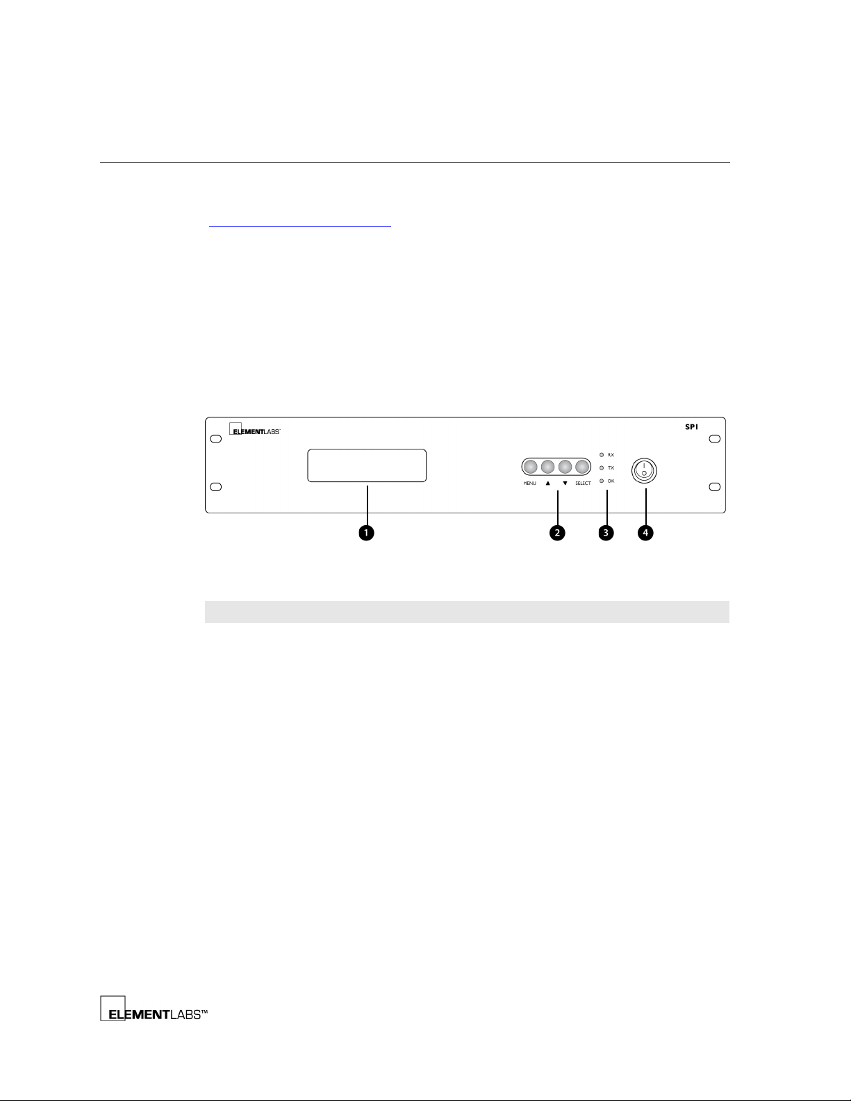
The following information describes the SP1 Front Panel:
Processing Components
Chapter 2
, p. 2-8). The SP1 incorporates a front panel menu
Figure 2.3
Legend # Item Function
1 LED Screen Displays setup menus
2Menu
SP1 Front Panel
Access
Buttons
Menu Used to access setup menus and functions
•In select item mode, press to return to the front
menu
• In change data mode, press to enter select item
mode
Increments the menu selection
5
•In select item mode, press to move the cursor up
to the previously selected item
• In change data mode, press to increase the data
value on the selected item
Decrements the menu selection
6
•In select item mode, press to move the cursor
down to the next selected item
• In change data mode, press to decrease the data
value of the selected item
Select Selects the displayed parameter
•In select item mode, press to enter the next menu
or change data mode
• In change data mode, press to return to select
item mode after saving
STEALTH® v2 User’s Guide 2-4
Page 12
Processing Components
www.shsglobal.store
Legend # Item Function
3Indicator
lights
4 Power Powers on/off the SP1
RXD RS232 signal is being received
TX RS232 signal is transsmitting
OK Indicates presence of incoming DVI signal
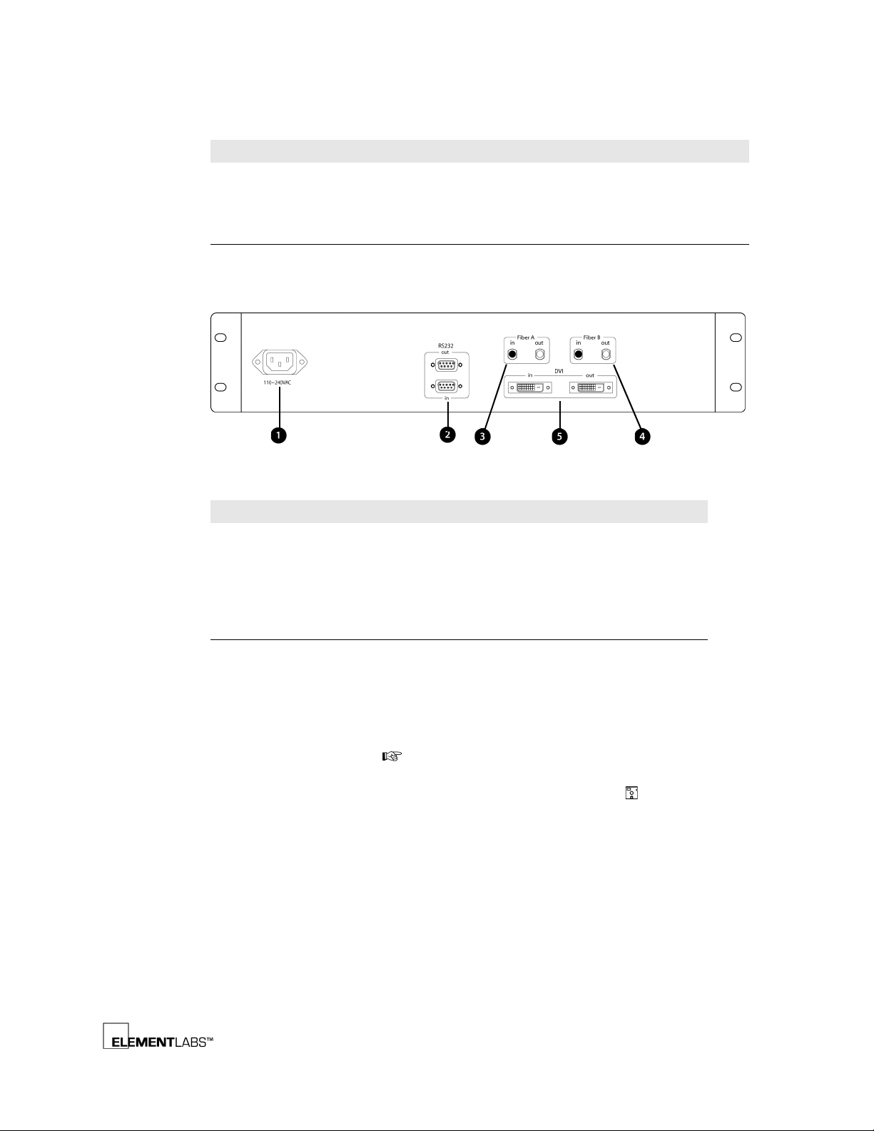
Rear Panel Description
The following information describes the SP1 rear panel connections:
Chapter 2
Figure 2.4
Legend # Connector Info
SP1 Rear Panel
1 AC Power Input Accepts between 85~240 VAC
2 RS232 In / Out Not used
3 Fiber A Out First image area data out to DD1
4 Fiber B Out Second image area data out to DD1
5 DVI In / Out DVI In: Signal from VP1 (1024x768 @ 60 Hz)
DVI Out: Loop Out to next SP1 or DVI Monitor
Menu Navigation
The SP1 front panel buttons allow you to navigate the menus and change
parameters. Button functionality varies depending upon the current menu mode.
There are 2 Menu Modes: Select Item and Change Data. Select Item mode,
indicated by a hand icon ( ), means that you are navigating the menus and will
be selecting an item that you wish to adjust. Once you have selected the item, you
are then in Change Data mode, indicated by a floppy disk icon ( ), where you will
actually be changing the setting.
STEALTH® v2 User’s Guide 2-5
Page 13

Processing Components
www.shsglobal.store
Chapter 2
The SP1 menu structure has one main menu and five sub-menus outlined in the
following table.
Table 2.1
Menu Item Description Values/
Display Brightness Set the source of the brightness setting
SP1 Menus & Value Ranges
Range
1-10
and the setting value
Gamma Set DD1 gamma table 1.0-3.0
SP1 SP1 ID Set the ID of SP1 1-255
Cascade SP1 Set the cascade amount of SP1 1-255
DD1 Image Offset Master offset for all pixel information sent
to DD1
Width Horizontal Offset 0-1023
Height Vertical Offset 0-1023
1
Ch 1-1 Offset for DD1-Fiber A output channel A X
=0-1023
2
Y
=0-1023
Ch 1-2 Offset for DD1-Fiber A output channel B X=0-1023
Y=0-1023
Ch 1-3 Offset for DD1-Fiber A output channel C X=0-1023
Y=0-1023
Ch 1-4 Offset for DD1-Fiber A output channel D X=0-1023
Y=0-1023
Ch 1-5 Offset for DD1-Fiber A output channel E X=0-1023
Y=0-1023
Ch 1-6 Offset for DD1-Fiber A output channel F X=0-1023
Y=0-1023
Ch 2-1 Offset for DD1-Fiber B output channel A X=0-1023
Y=0-1023
Ch 2-2 Offset for DD1-Fiber B output channel B X=0-1023
Y=0-1023
Ch 2-3 Offset for DD1-Fiber B output channel C X=0-1023
Y=0-1023
Ch 2-4 Offset for DD1-Fiber B output channel D X=0-1023
Y=0-1023
Ch 2-5 Offset for DD1-Fiber B output channel E X=0-1023
Y=0-1023
Ch 2-6 Offset for DD1-Fiber B output channel F X=0-1023
Y=0-1023
SBU Display Mode
Mode Selects live input (Normal), generates test
pattern (Line), triggers internal DSU test
Normal, Line,
Pattern, All
(Pattern & All)
STEALTH® v2 User’s Guide 2-6
Page 14

Processing Components
www.shsglobal.store
Chapter 2
Table 2.1
Menu Item Description Values/
SP1 Menus & Value Ranges
Pat Selects DSU test patterns under PATTERN
mode
Range
Black, White,
Red, Green,
Blue,
Pattern1,
Pattern2,
Pattern3,
Pattern4,
Column1,
Column2,
Row1, Row2,
ID
All W.B. Set scan board white balance individually
for Red, Green, and Blue components
R=0-255
G=0-255
B=0-255
Link Direction Selects the behavior of successive DSU
outputs from horizontal to vertical
Left to Right,
Down to Up,
Up to Down
Block Size Selects horizontal (width) and vertical
(height) pixel block output size. Should
Width: 1-255
Height: 1-255
always be set at 16x80 for STEALTH
systems.
Information Displays system information. Values are
unchangeable.
SP1 Version Shows Version and Date.
PC Com Mode Shows Mode and Channel information.
1.X = horizontal offset
2.Y = vertical offset
STEALTH® v2 User’s Guide 2-7
Page 15
DD1 – Data Distribution Unit
www.shsglobal.store
The following is a list of DD1 features:
• fiber optic input from SP1
• 1024x256 pixels (96 columns x 16 rows) maximum display area
• six output ports 400x80 pixels (25 columns x 5 rows)
• additional DD1 required for every additional 256 vertical pixels (16
rows) of screen area
Processing Components
Chapter 2
NOTE
You will need a 50/125 fiber optic cable with ST-ST connectors.
Front Panel Description
The following information describes the DD1 Front Panel:
Figure 2.5
Item Function
OK Solid green when running normally
Link Solid red if a problem occurs.
DD1 Front Panel
Flashing red during communications
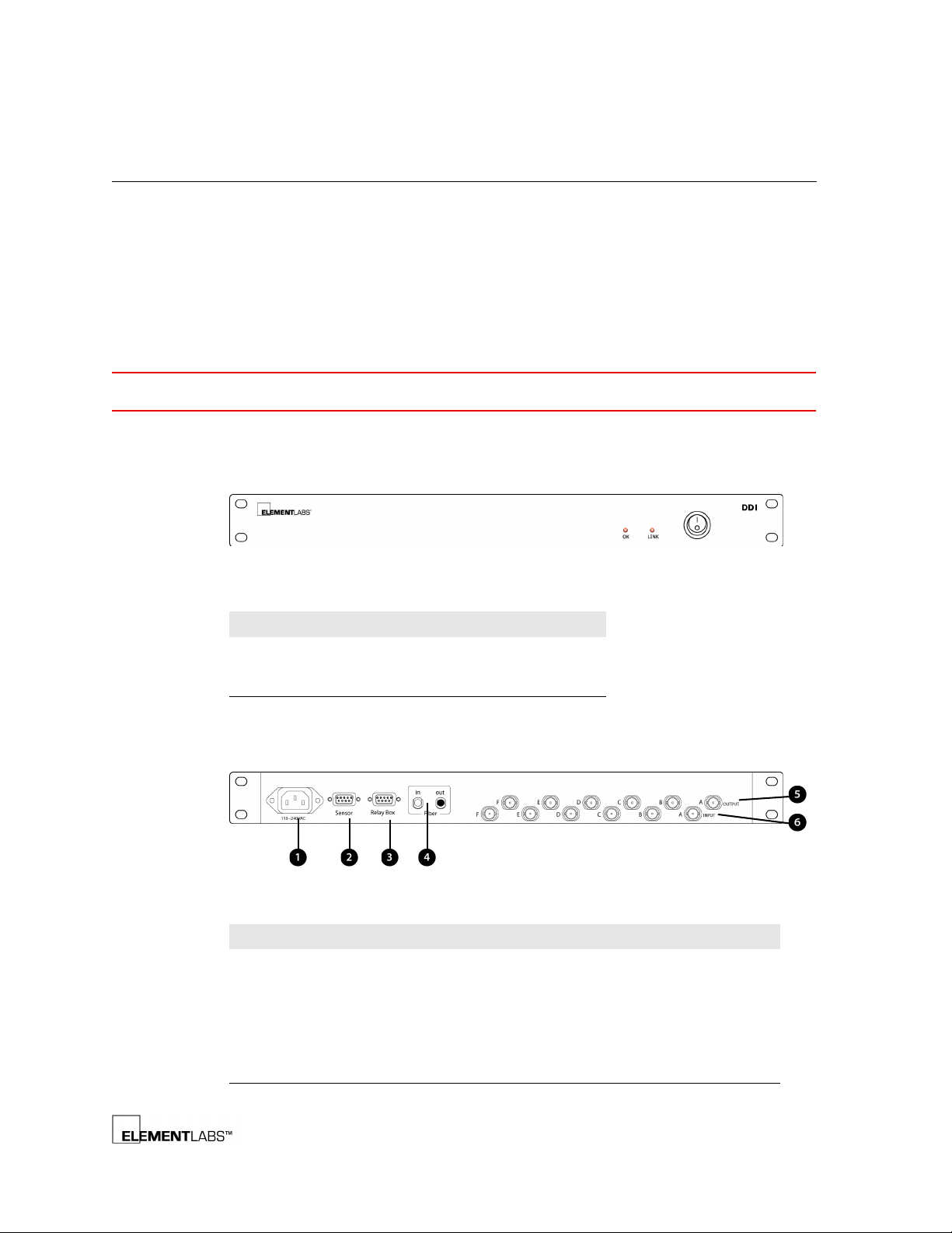
Rear Panel Description
The following information describes the DD1 rear panel connections:
Figure 2.6
Legend # Connector Info
DD1 Rear Panel
1 AC Power Input Accepts between 85~264 VAC
2 Sensor Unused
3Relay Box Unused
4 Fiber In Data from the SP1
5 Signal Outputs A-F Data output
6 Signal Inputs A-F Unused
STEALTH® v2 User’s Guide 2-8
Page 16
PDB-3 – Power and Data Distribution
www.shsglobal.store
The PDB-3 handles the distribution of power and data to the STEALTH panels. Each
PDB-3 includes the following features:
• Two x 1U High Data Supply Units (DSU)
• DC Output Panel, 1U High
• Multiple PDB-3s Can Be Connected
Front Panel Description
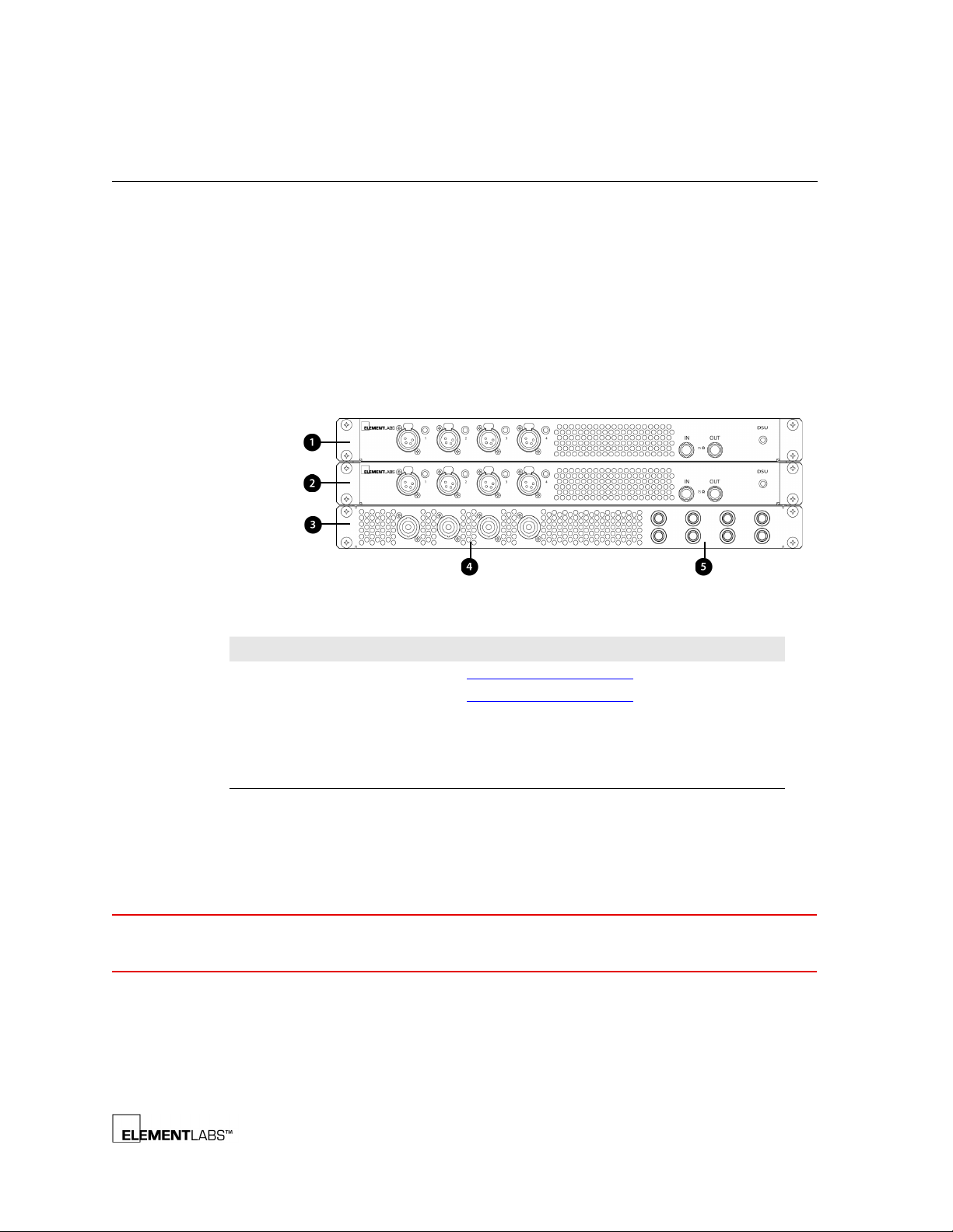
As shown below, each PDB-3 contains 3 individual chassis: 2 DSUs and 1 DC Output
Panel. The following information describes the front of the PDB-3:
Processing Components
Chapter 2
NOTE
Figure 2.7
Legend # Item Info
PDB-3 Front Panel
1 DSU #1 See DSU – Data Supply Unit (p. 2-12) for more info
2 DSU #2 See
3 DC Output Panel Handles the power output to the STEALTH panels
4 Power Output Cable with Neutrik NL-4 connector breaks out to 2x
5 Circuit Breakers 15 amp (push to reset)
DSU – Data Supply Unit (p. 2-12) for more info
LTW connectors
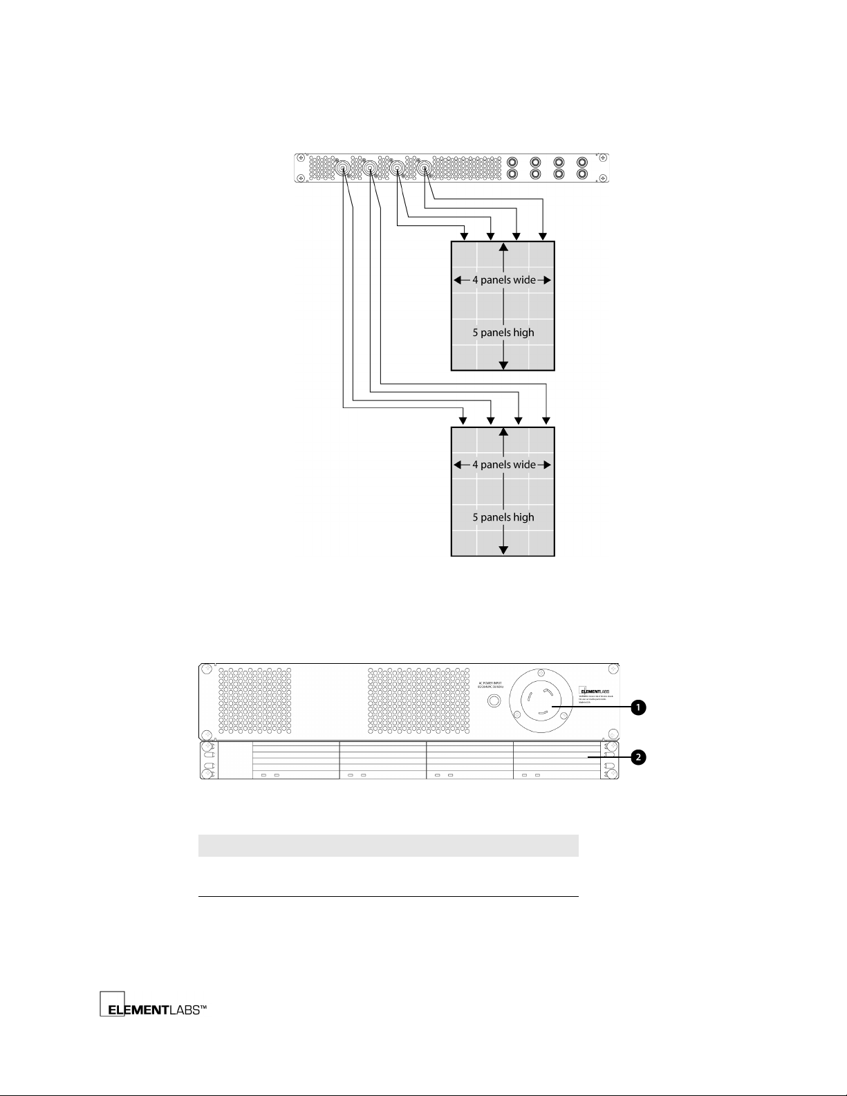
The DC Output Panel contains 4 Speakon connectors for distributing 48VDC power
to the STEALTH panels. Each of these power connectors breaks out to 2 LTW
connectors that can drive two columns of 5 panels each. Do not daisy chain more
than 5 panels together.
LTW power and data cables from the PDB-3 to the STEALTH panels must be no
longer than 8 meters.
STEALTH® v2 User’s Guide 2-9
Page 17
Processing Components
www.shsglobal.store
The following diagram illustrates basic PDB to STEALTH Power connections:
Chapter 2
Figure 2.8
PDB Power Connection Diagram
Rear Panel Description
The following information describes the rear of the PDB-3:
Figure 2.9
Legend # Item
PDB-3 Rear Panel
1 Power Input Connector (see below)
2 Removable Power Supplies
STEALTH® v2 User’s Guide 2-10
Page 18
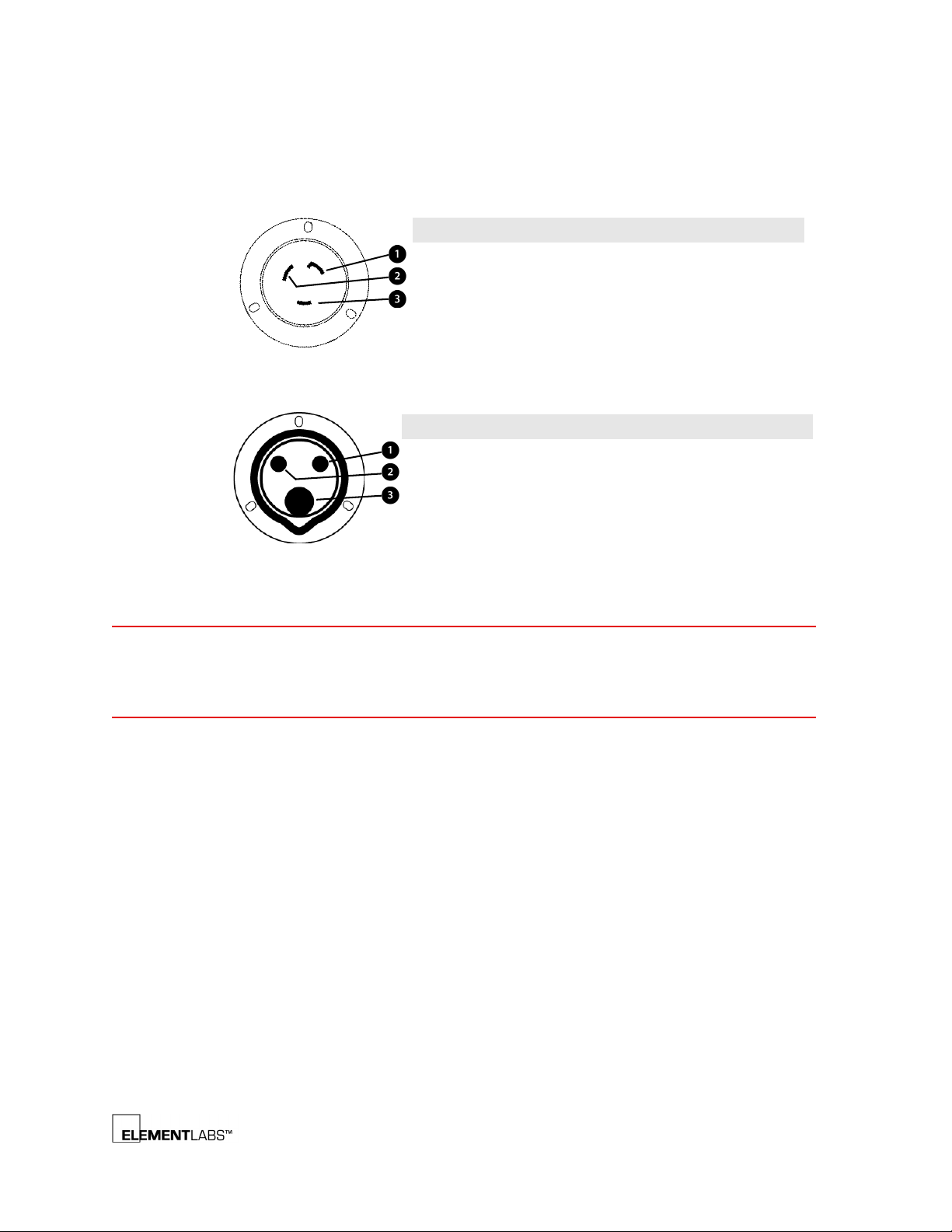
Processing Components
Item Wire Color Info
Ground Green
Hot Leg X Black 180-264 VAC, 47/63 Hz
Nominally: 200-240 VAC, 50/60Hz
Hot Leg Y Red
Item Wire Color Info
Hot Leg X Brown 180-264 VAC, 47/63 Hz
Nominally: 200-240 VAC, 50/60Hz
Neutral Blue
Ground Green + Yellow
www.shsglobal.store
Chapter 2
Each PDB-3 is configured with either a NEMA L6-30 (North America, 30 amp) or
IEC 60309 - CEE 17 (EU, 32 amp) power input connector mounted on the rear of the
chassis for main power input.
NOTE
Figure 2.10
Figure 2.11
PDB-3 NEMA LC-30 Male Power Input Connector, front view
PDB-3 IEC 60309 - CEE 17 Male Power Input Connector, front view
US 120/208v power: you need to run two hot legs on separate phases and a ground
to reach the required voltage.
EU 240v power: you need one hot leg, a neutral, and ground.
STEALTH® v2 User’s Guide 2-11
Page 19
DSU – Data Supply Unit
Address Value
1
2
4816
www.shsglobal.store
The DSU handles the final data output to the STEALTH panels. Each DSU contains
four Scan Boards (SB) which must be addressed properly to match your
configuration.
For example, if you are going to use 8 columns of STEALTH panels the DIP switches
for the first 4 SBs must be set to 1-4. The next DSU SBs need to be set to 5-8.
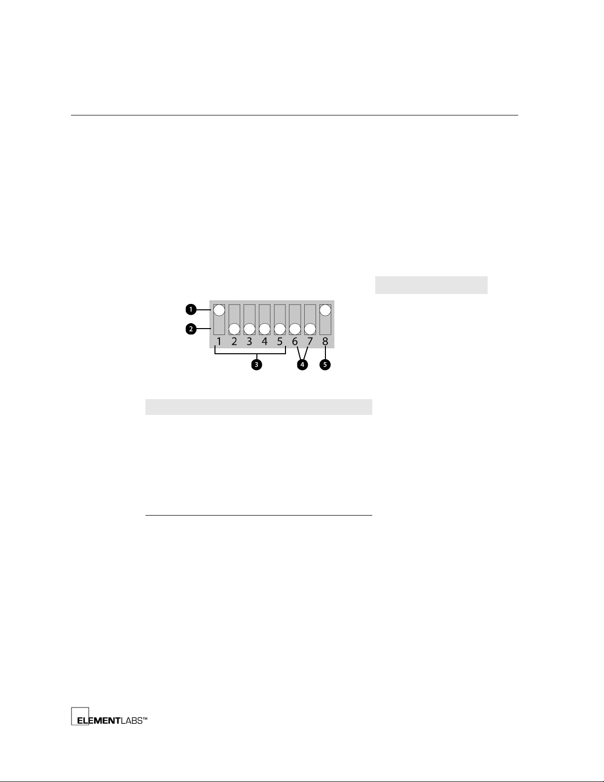
Each DIP switch has 8 individual switches which allow you to set the Binary ID for
that SB. Each of the 8 individual switches can be set to On or Off. When set to the
On (up) position, there is a value associated with that setting. The overall value is
obtained by adding the individual values of switches 1-5. The following
information describes a Scan Board DIP switch:
Processing Components
Chapter 2
DIP Switch Binary Value
11
22
34
48
516
Figure 2.12
Legend # Item Description
Scan Board DIP Switch
1Up On
2Down Off
3 Switches 1-5 Used for SB addressing
4 Switch 6 & 7 Unused
5 Switch 8 Used for either video
mode (up position) or
test pattern mode
(down position)
STEALTH® v2 User’s Guide 2-12
Page 20
Processing Components
www.shsglobal.store
Chapter 2
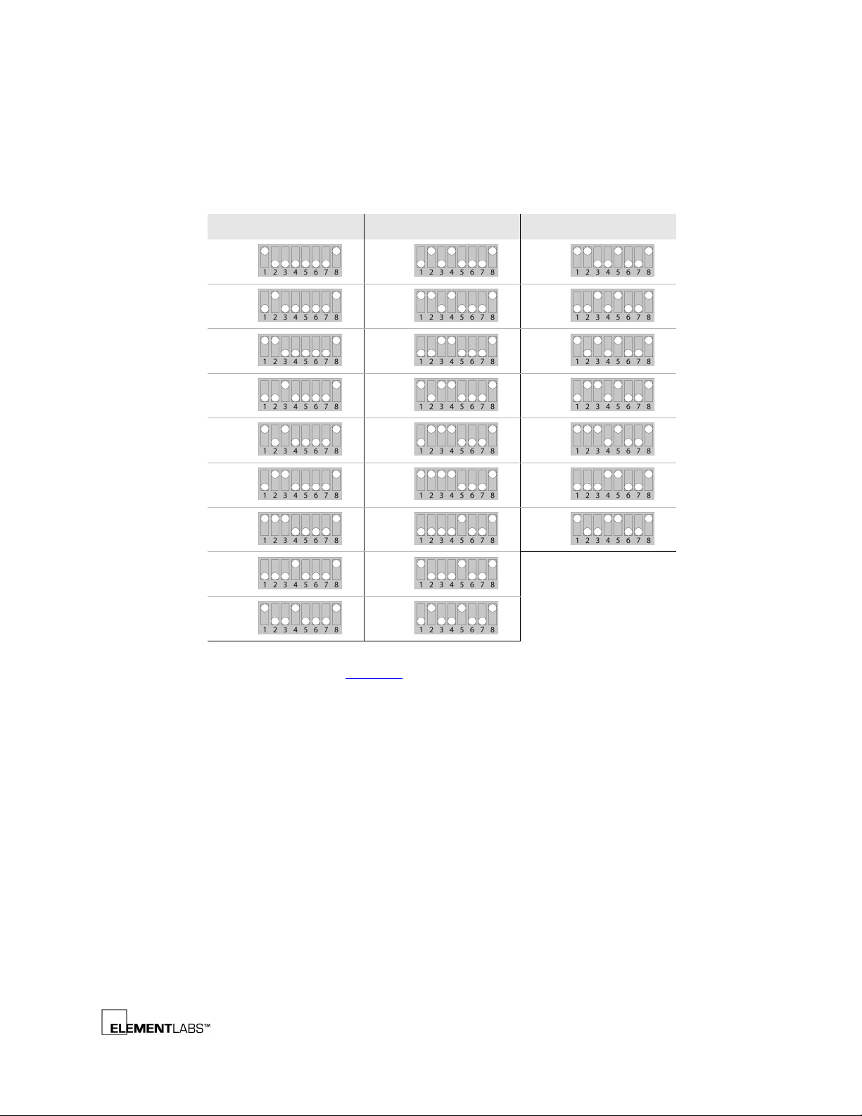
The following table lists the individual DIP switch values along with an image of
how the DIP switch should be set:
Table 2.2
Value Image Value Image Value Image
11019
21120
31221
41322
51423
61524
71625
817
DIP Switch Values
918
As an example, using Table 2.2
above, #7 has switches 1, 2, and 3 in the up position.
So simply add the values from switches 1, 2, and 3 (1 + 2 + 4) to get the overall
value of 7.
STEALTH® v2 User’s Guide 2-13
Page 21
Front Panel Description
www.shsglobal.store
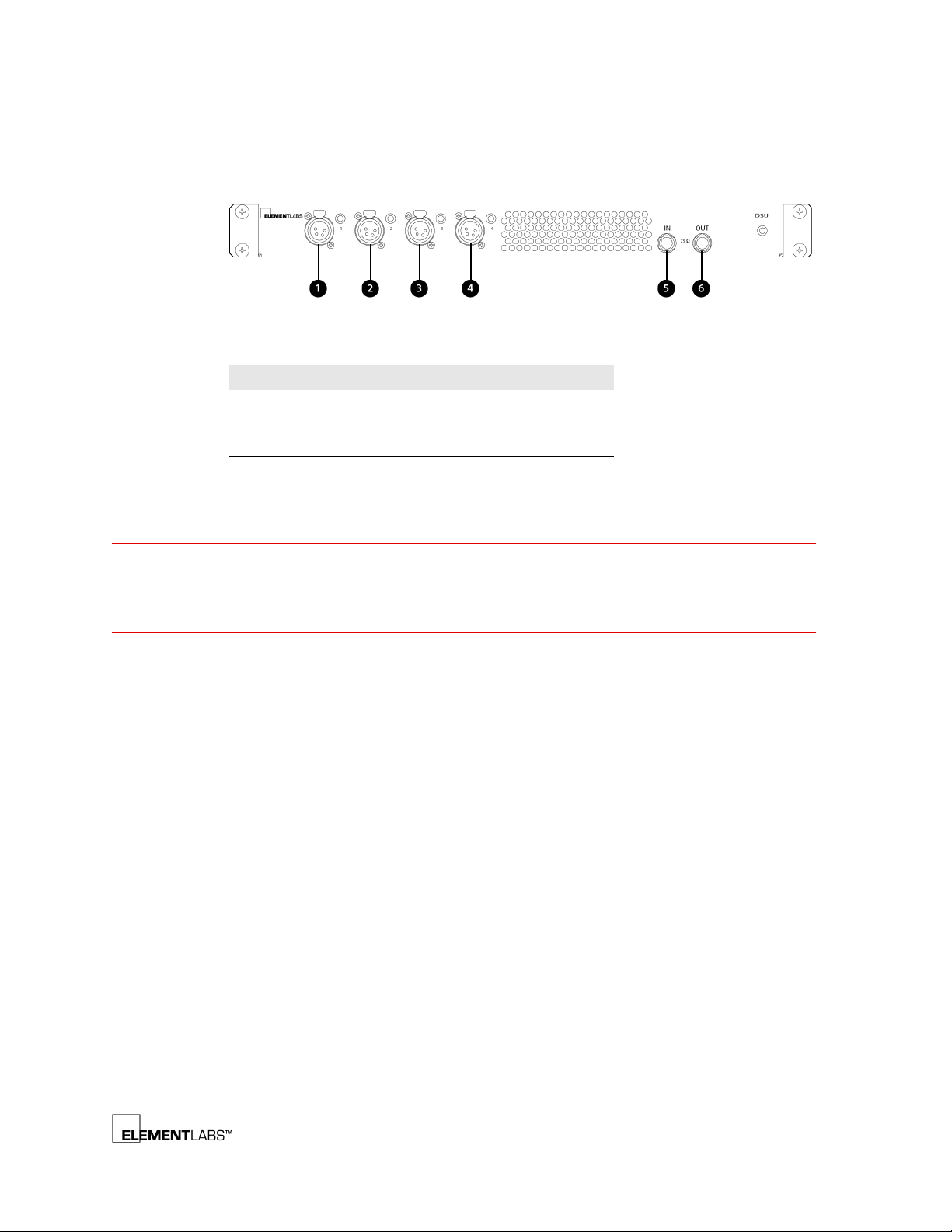
The following information describes the DSU Front Panel:
Processing Components
Chapter 2
NOTE
Figure 2.13
Legend # Function
1-4 Data Output 1-4
DSU Front Panel
5 Coaxial In
6 Coaxial Out
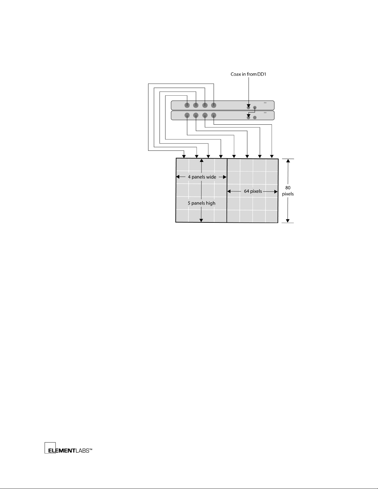
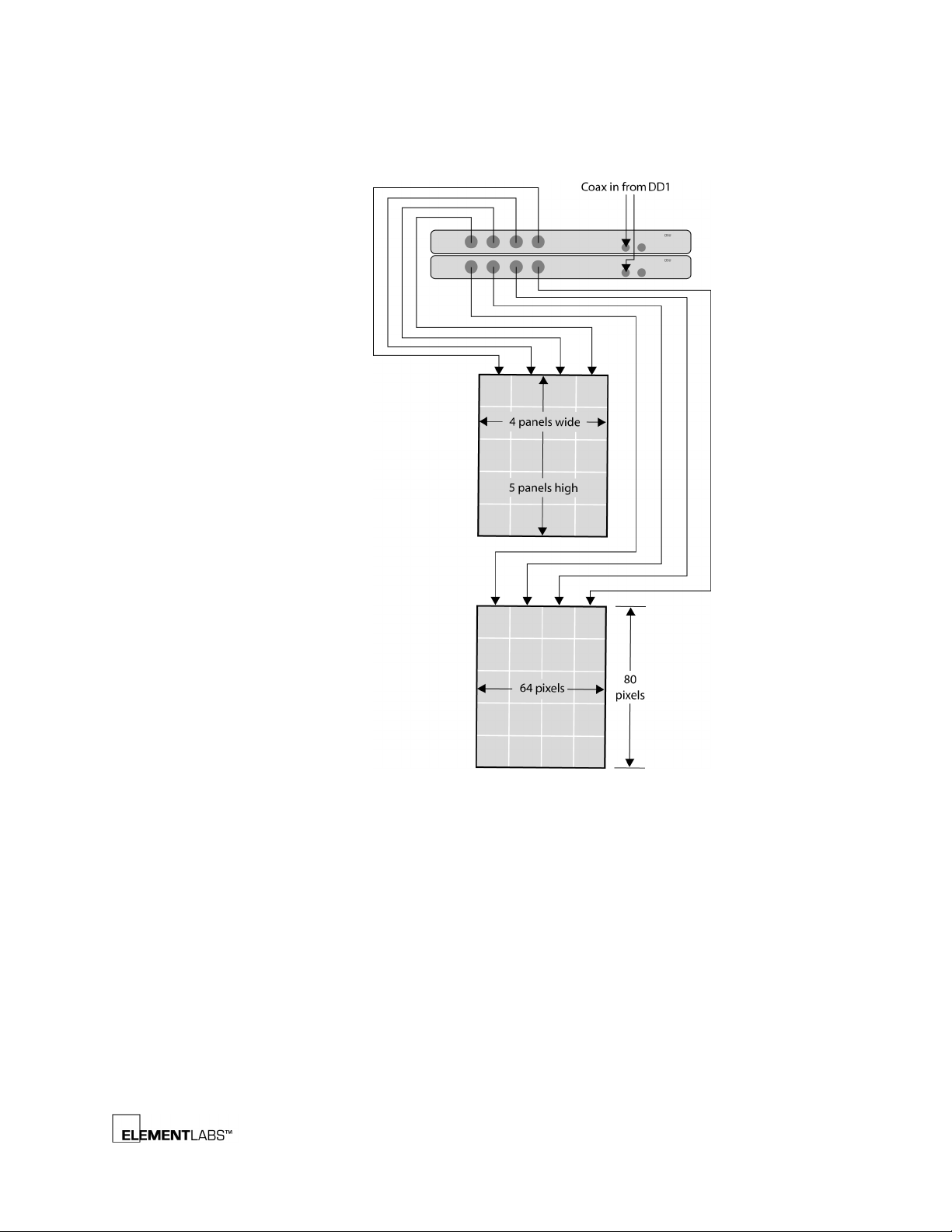
Data output from each DSU is made through the front mounted, 4 pin, female XLR
connector.
To connect to the STEALTH panels, you will need to use XLR to LTW adaptors.
LTW power and data cables from the PDB-3 to the STEALTH panels must be no
longer than 8 meters.
STEALTH® v2 User’s Guide 2-14
Page 22
Processing Components
www.shsglobal.store
The following diagrams illustrate basic DSU signal and control connections:
Chapter 2
Figure 2.14
DSU Signal and Control Connection Diagram #1
STEALTH® v2 User’s Guide 2-15
Page 23
Processing Components
www.shsglobal.store
Chapter 2
Figure 2.15
DSU Signal and Control Connection Diagram #2
STEALTH® v2 User’s Guide 2-16
Page 24

C HAPTER
www.shsglobal.store
Chapter 3 R
This chapter introduces you to the rigging and mechanical aspects of the STEALTH
System and covers the following topics:
• Overview
• Header Assembly
• STEALTH Panel
, (p. 3-2)
, (p. 3-3)
, (p. 3-5)
IGGING AND
M
ECHANICAL
STEALTH® v2 User’s Guide 3-1
Page 25
Overview
www.shsglobal.store
Rigging and Mechanical
Chapter 3
Each STEALTH panel measures 398.5 mm (15.69”) long by 38.5 mm (1.52”) wide by
400 mm (15.75”) high and contains 256 LEDs in a 16 x 16 array. Multiple panels can
be assembled together to attain the desired screen size.
NOTE
The maximum # of panels that can be connected vertically is 60.
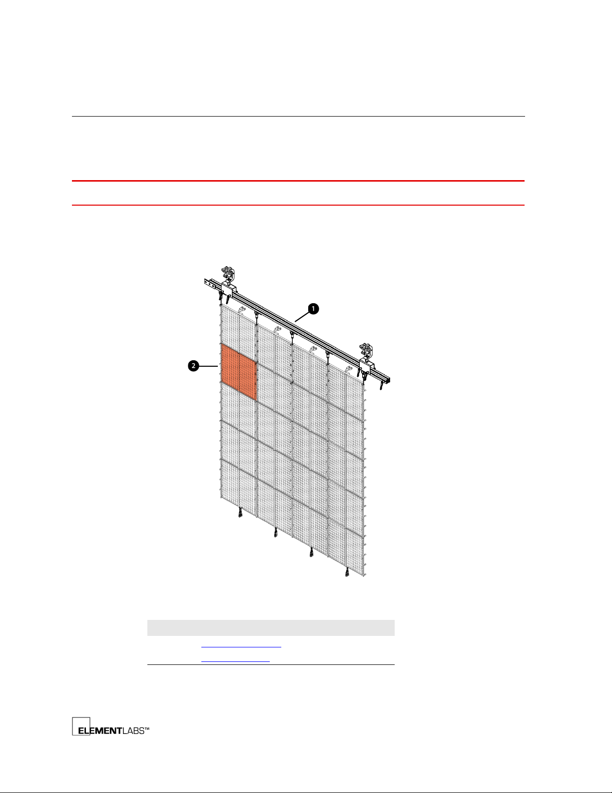
The following information describes a STEALTH panel assembly in a 4 panel wide
by 5 panel high configuration. Each of the main parts are discussed in subsequent
pages.
Figure 3.1
Legend # Function
STEALTH 4x5 Panel Assembly
1 Header Assembly, (p. 3-3)
2
STEALTH Panel, (p. 3-5)
STEALTH® v2 User’s Guide 3-2
Page 26
Header Assembly
www.shsglobal.store
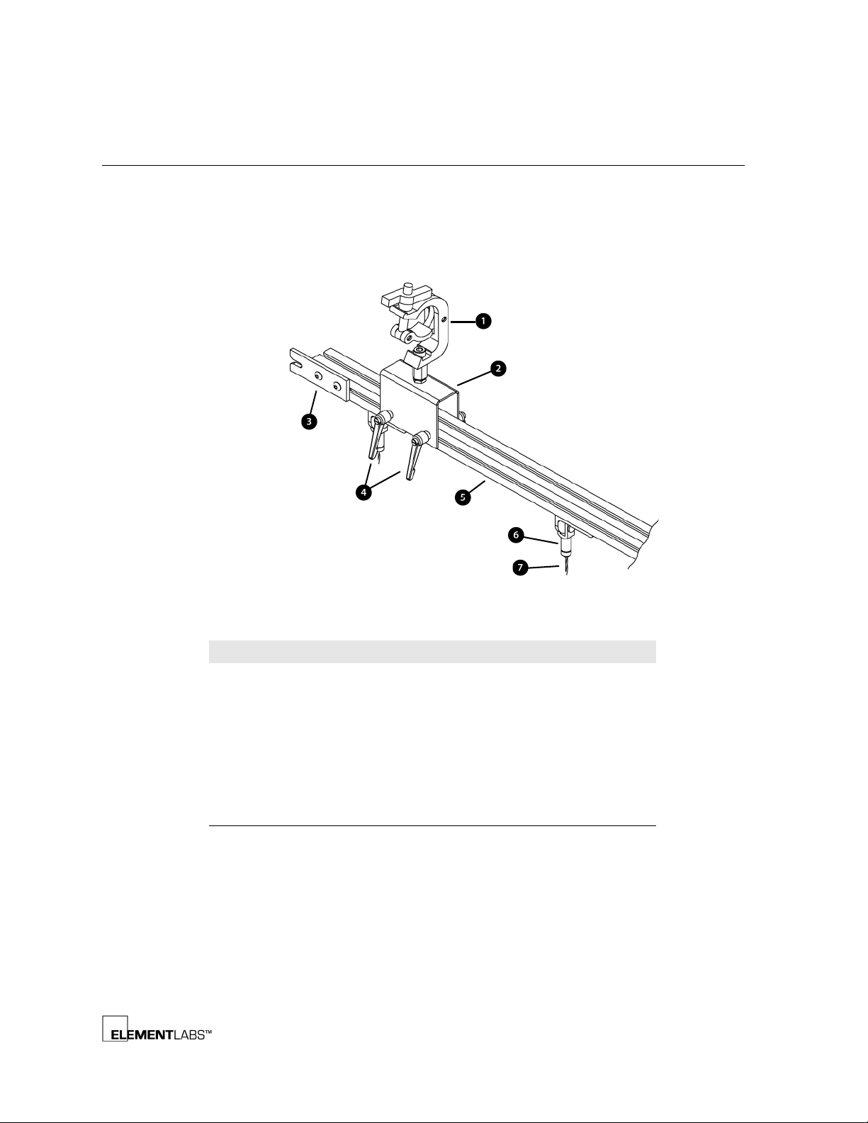
The header assembly provides an easy way to hang STEALTH panels. Common
rigging hardware is used to allow for flexible installation adjustments.
Description
The following information describes the STEALTH header:
Rigging and Mechanical
Chapter 3
Figure 3.2
Legend # Function
STEALTH Header Detail
1 Cheeseborough Clamp
2 Adjustable Clamp Bracket
3 Joining Plate for Multiple Headers
4 Horizontal Adjustment Levers
5Header Bar
6Grip Lock
7 Option 1: Cable for Attaching STEALTH Panels
Option 2: v2.5 Hinge Connector (not shown)
STEALTH® v2 User’s Guide 3-3
Page 27
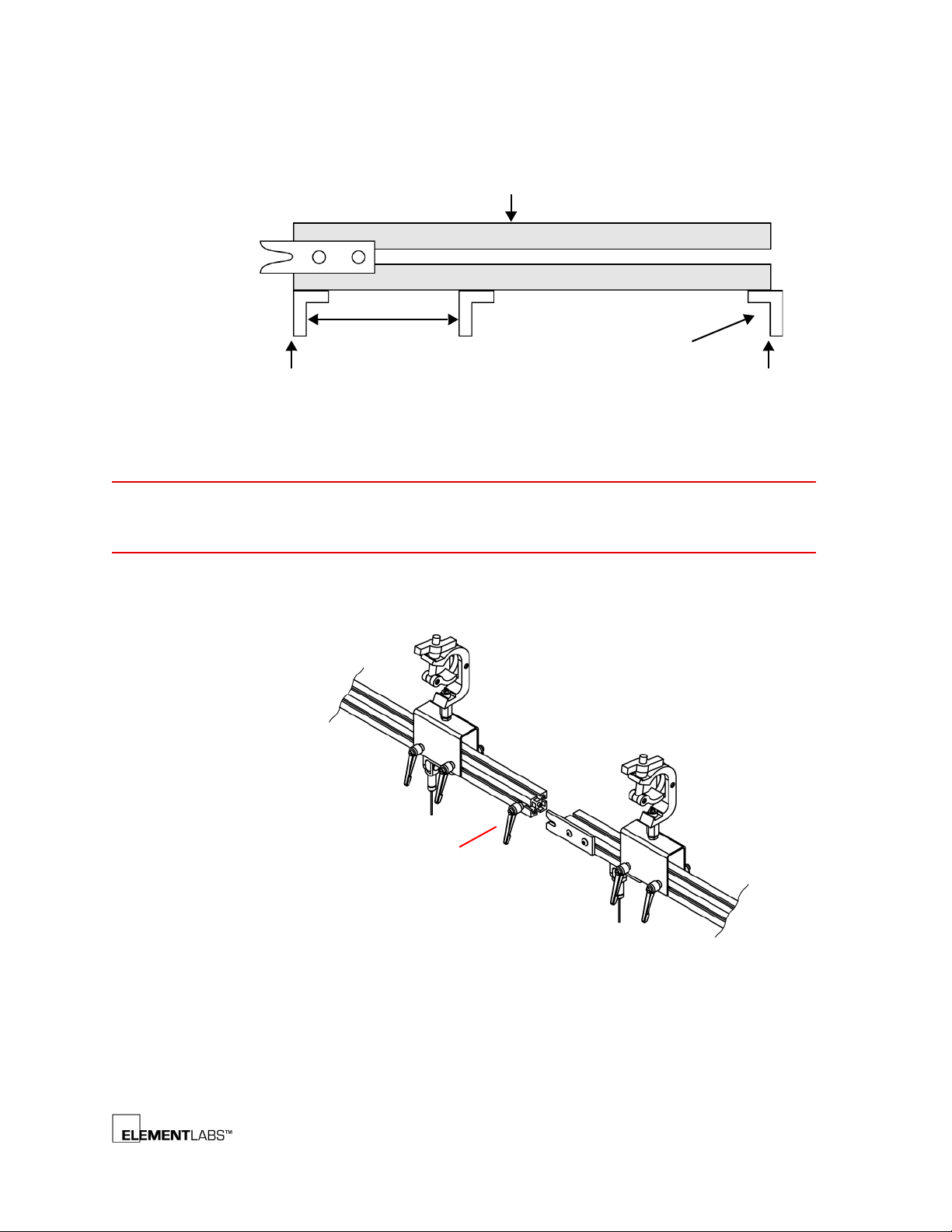
Rigging and Mechanical
Flush with
Outside of “L”
Flush with
Inside of “L”
Header
Remove this “L” bracket
for use with another
header to the right.
400 mm
NOTE: Tighten
interconnect lever for
transport to prevent
loss.
www.shsglobal.store
The following illustration offers more details of the STEALTH header.
Chapter 3
NOTES
Figure 3.3
STEALTH Header More Details
Check all fasteners and hardware before using.
Use only for hanging STEALTH panels.
Connecting Multiple Headers
Multiple STEALTH headers can be connected together as shown in the illustration below.
Figure 3.4
Connecting Multiple Headers
STEALTH® v2 User’s Guide 3-4
Page 28
STEALTH Panel
www.shsglobal.store
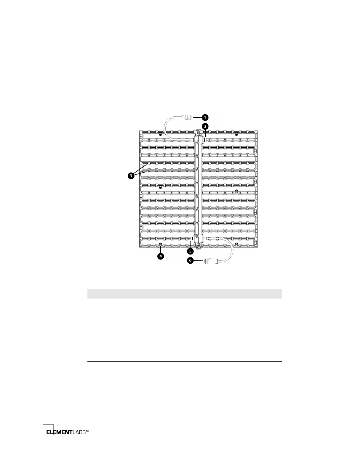
Each STEALTH panel measures 398.5 mm (15.69”) long by 38.5 mm (1.52”) wide by
400 mm (15.75”) high and contains 256 LEDs in a 16 x 16 array. Multiple panels can
be attached together to attain the desired screen size.
The following information describes a STEALTH panel:
Rigging and Mechanical
Chapter 3
Figure 3.5
Legend # Function
STEALTH Panel Detail
1 Data input cable (smaller LTW connector)
2 Power input jack (larger LTW connector)
3 LEDs (total of 256 per panel)
4 Mounting hole (6 per panel)
5 Data output jack (smaller LTW connector) Used to connect to
other panels
6 Power output cable (larger LTW connector). Used to connect to
other panels
STEALTH® v2 User’s Guide 3-5
Page 29
Rigging and Mechanical
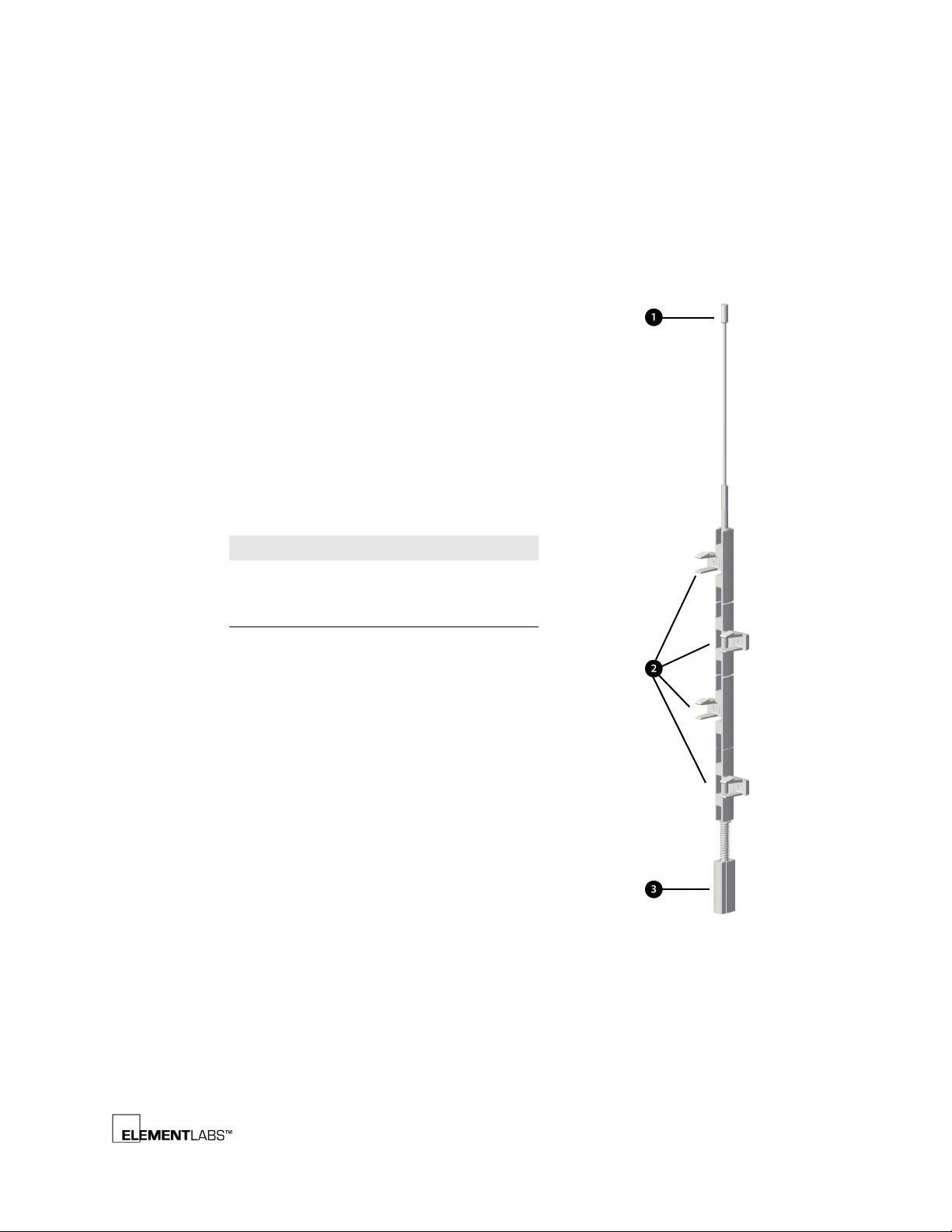
Legend # Function
1Mating Pin
2 STEALTH Panel Snaps
3 Spring Loaded Collar
www.shsglobal.store
Chapter 3
Connecting Multiple STEALTH Panels
Multiple STEALTH panels can be easily connected via the included hinge assembly.
Once connected, you can snap in/out individual panels as needed and even fold up
the entire STEALTH curtain for transport.
The following information describes the STEALTH v2.5 hinge assembly (a detailed
illustration of the hinge connection follows):
Figure 3.6
STEALTH Panel Hinge Assembly
STEALTH® v2 User’s Guide 3-6
Page 30
Rigging and Mechanical
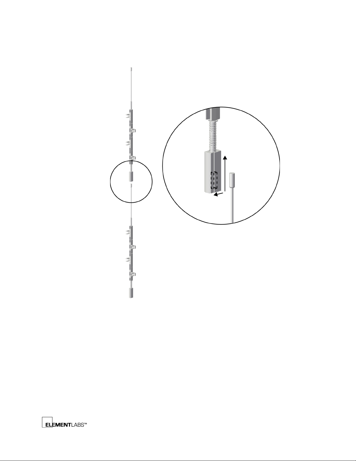
Collar Slides
Up to Accept
Mating Pin
Mating pin slides
and locks in place.
www.shsglobal.store
Chapter 3
The following information describes the STEALTH v2.5 hinge connection assembly:
Figure 3.7
STEALTH Panel Hinge Connection Detail
STEALTH® v2 User’s Guide 3-7
Page 31
Rigging and Mechanical
www.shsglobal.store
Chapter 3
Folding STEALTH Panels
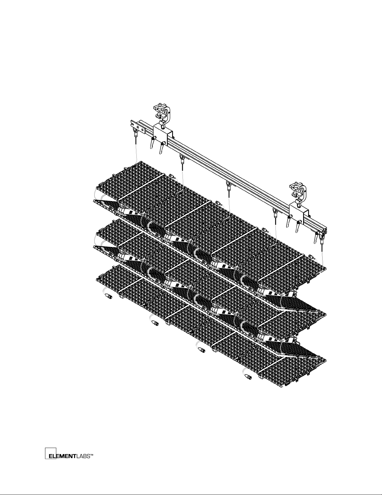
If you are using the cable hinge, STEALTH panels can be folded together as shown in
the following illustration.
Figure 3.8
Folding STEALTH Panel Assembly
STEALTH® v2 User’s Guide 3-8
Page 32

Rigging and Mechanical
www.shsglobal.store
Chapter 3
Power & Data Connections
The power and data connections from the PDB-3 (PDB-3 – Power and Data
Distribution, p. 2-9) to each STEALTH panel are daisy-chained within each column
or row, depending upon your type of configuration. The first data connection is
plugged into the top of a panel via the pigtail with the smaller LTW connector.
Subsequent data connections are made by plugging the second panel’s pigtail into
the LTW jack at the bottom of the first panel.
The first power connection is made with the larger LTW connector and the jack
mounted on the rear of the STEALTH panel. Subsequent power connections
between panels are made by plugging in the first panel’s pigtail into the LTW jack
at the top of the second panel.
STEALTH® v2 User’s Guide 3-9
Page 33

A PPENDIX
www.shsglobal.store
Appendix A
S
PECIFICATIONS
This chapter covers the STEALTH system specifications and is divided into the
following sections:
• VP1 Specifications
• SP1 Specifications
• DD1 Specifications
• PDB-3 Specifications
• DSU Specifications
• STEALTH Panel Specifications
(p. A-2)
(p. A-3)
(p. A-4)
(p. A-5)
(p. A-6)
(p. A-7)
STEALTH® v2 User’s Guide A-1
Page 34

VP1 Specifications
www.shsglobal.store
The following table lists the VP1 (Video Processing Unit) specifications:
Item Specification
Inputs
Outputs 2xDVI 1024x768
Vertical Frequency 60 Hz
Dimensions (H) 44.45 mm (1.75”/1U)
Weight 4.49 kg (9.9 lbs)
Power 110-240 VAC, 50/60 Hz
Appendix A
Specifications
Format Resolution
DVI 1024x768
SD-SDI 720x486
HD-SDI 720x486
Component 640x480
S-Video 720x486
Composite 640x480
(W) 482.6 mm (19”)
(D) 266.7 mm (10.5”)
10.6 watts
STEALTH® v2 User’s Guide A-2
Page 35

SP1 Specifications
www.shsglobal.store
The following table lists the SP1 (Signal Processing Unit) specifications:
Item Specification
Inputs
Outputs 2xFiber
Vertical Frequency 60 Hz
Dimensions (H) 44.45 mm (1.75”/1U)
Weight 5.03 kg (11.1 lbs)
Power 110-240 VAC, 50/60 Hz
Appendix A
Specifications
Format Resolution
DVI 1024x768
DVI (loop through)
(W) 482.6 mm (19”)
(D) 285.75 mm (11.25”)
8.0 watts
STEALTH® v2 User’s Guide A-3
Page 36

DD1 Specifications
www.shsglobal.store
The following table lists the DD1 (Data Distribution Unit) specifications:
Item Specification
Input Fiber
Outputs 6x Coaxial BNC
Dimensions (H) 44.45 mm (1.75”/1U)
Weight 4.13 kg (9.1 lbs)
Power 110-240 VAC, 50/60 Hz
Appendix A
Specifications
192,000 pixels (max)
(W) 482.6 mm (19”)
(D) 266.7 mm (10.5”)
11.7 watts
STEALTH® v2 User’s Guide A-4
Page 37

PDB-3 Specifications
www.shsglobal.store
The following table lists the PDB-3 (Power and Data Distribution) specifications:
Item Specification
Inputs (data) See DSU Specifications (p. A-6)
Outputs (data) See
Outputs (power) 48VDC via 4xSpeakon
Max Cable Length
(power & data)
Dimensions (H) 177.80 mm (7.00”)
Weight 31.64 kg (69.75 lbs)
Circuit Breakers 15 amp (push to reset)
Power 180-264 VAC, 47/63 Hz
Appendix A
Specifications
DSU Specifications (p. A-6)
Connectors (chassis mounted)
2xLTW Connectors (via breakout cable)
8 meters (between PDB-3 and STEALTH panel)
(W) 533.40 mm (21.00”)
(D) 609.6 mm (24.00”)
Nominally: 200-240 VAC, 50/60Hz
NEMA L6-30 connector (North America)
IEC 60309 connector (EU)
STEALTH® v2 User’s Guide A-5
Page 38

DSU Specifications
www.shsglobal.store
The following table lists the DSU (Data Supply Unit) specifications:
Item Specification
Inputs Coaxial via BNC
Outputs Coaxial via BNC (loop through)
Dimensions (H) 44.45 mm (1.75”/1U)
Weight 3.63 kg (8 lbs)
Power 85-264 VAC, 50/60 Hz
Appendix A
Specifications
4xXLR (4 pin female)
(W) 482.6 mm (19”)
(D) 406.4 mm (16”)
27.5 watts
STEALTH® v2 User’s Guide A-6
Page 39

STEALTH Panel Specifications
www.shsglobal.store
The following table lists the STEALTH panel specifications:
Appendix A
Specifications
Table 3.1
Item Specification
Resolution 25 mm pixel pitch
Colors Trillions (48-bit)
Power 70 watts / panel
Output 2400 nits (average)
Transparency 60% (Aperture Ratio)
Bezel Color Black or White
Dimensions (L) 398.5 mm (15.69”)
Weight 1.0 kg (2.2 lbs)
STEALTH panel specifications
(W) 38.5 mm (1.52”)
(H) 400 mm (15.75”)
STEALTH® v2 User’s Guide A-7
Page 40

A PPENDIX
www.shsglobal.store
Appendix B
L
EDGURU SOFTWARE
This chapter covers the LedGuru software used for control of the STEALTH Video
Processing Unit (VP1). This appendix is divided into the following major categories:
• Communication Setup
• Input Tab
• Output Tab
• Pattern Generator
• File Load Save
(p. B-3)
(p. B-4)
(p. B-7)
(p. B-8)
(p. B-2)
STEALTH® v2 User’s Guide B-1
Page 41
Communication Setup
www.shsglobal.store
The following is a list of the requirements for using LedGuru software:
• Microsoft Windows-Compatible OS
•Serial Port
•Serial Cable
A USB high speed serial adapter cable, such as the Keyspan model #USA-19HS, can
be used to connect your computer to the VP1.
When LedGuru runs it automatically checks all available com ports to see if a VP1 is
connected. If one is found LedGuru asks the user if they would like to read settings
from the VP1 to ensure the software & hardware settings match.
Appendix B
LedGuru Software
NOTE
LedGuru will not launch if no com port is detected.
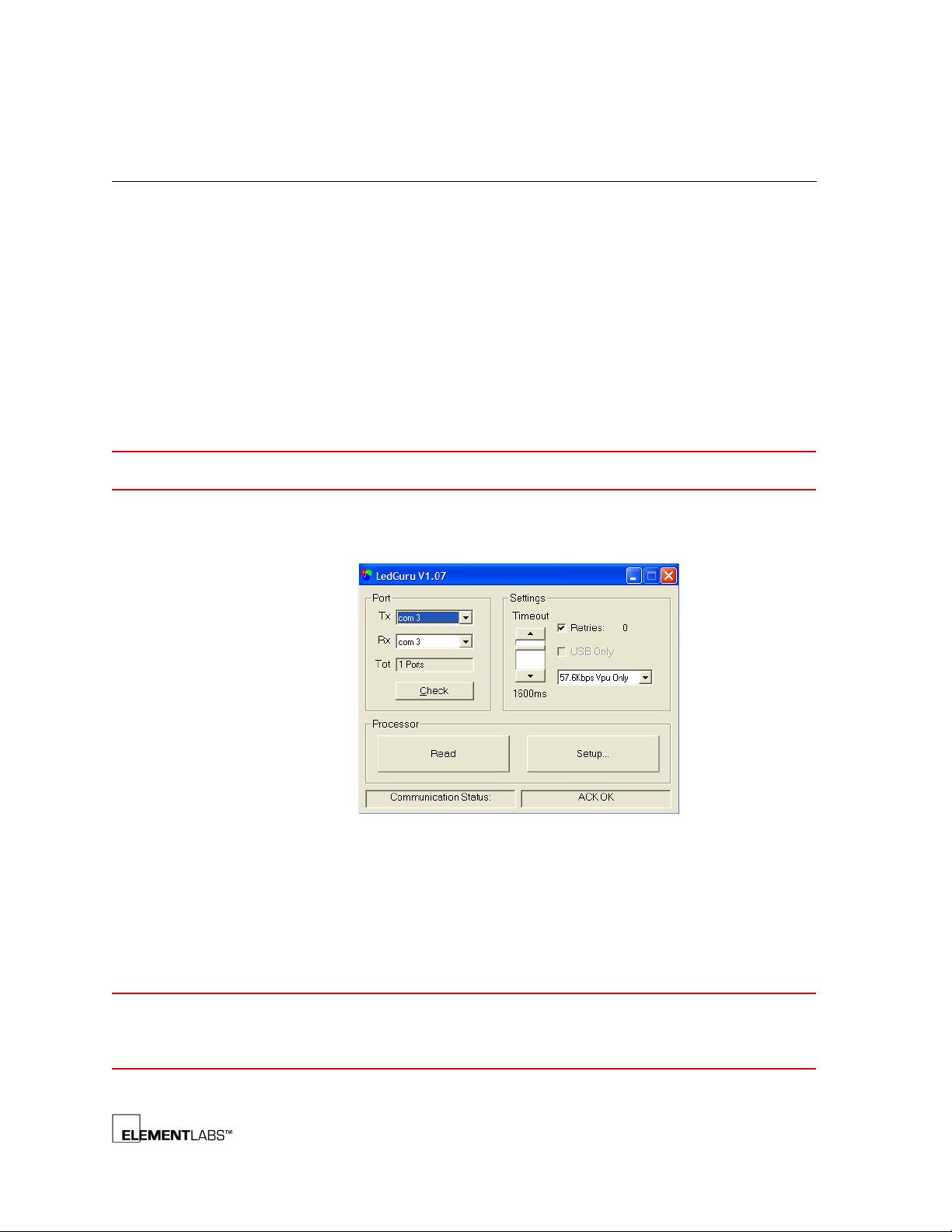
If LedGuru does not find a VP1 connected, the Com Setup screen is displayed as
shown in the following figure.
Figure 3.9
LedGuru Communications Setup Screen
Com ports and baud rates can be changed as required to establish
communications with the VP1. Click Check to repeat the search for a VP1.
NOTE
The default baud rate is 57.6Kbps. However, if a slower rate is required for
communication over a long cable, then speeds down to 9600 can be selected.
Both LedGuru and the VP1 remember the last selected baud rate in non-volatile
memory. Therefore, when connecting to a VP1 for the first time you may need
adjust the baud rate and hit Check to find which baud rate the VP1 is set to.
STEALTH® v2 User’s Guide B-2
Page 42
Input Tab
www.shsglobal.store
Appendix B
LedGuru Software
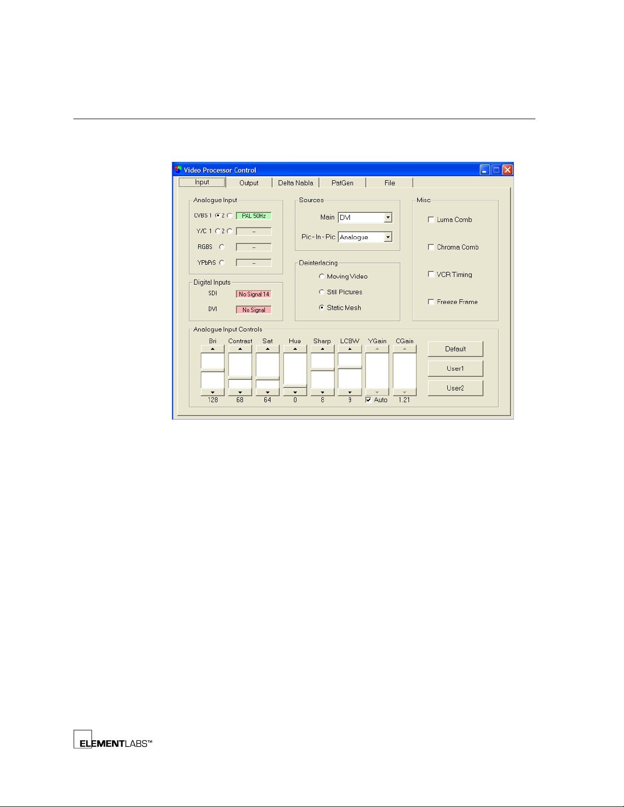
The LedGuru Input tab allows the user to select inputs and adjust various input
parameters.
Figure 3.10
The VP1 will accept three active video inputs simultaneously: analog, SDI and DVI.
Any two of these inputs can be displayed simultaneously using the Main and
Picture-in-Picture scaling channels. Only one analog input can be selected at a
time. The signal indication for the currently selected analog input is updated when
the signal is first selected (continuous signal status polling will be added in a later
release). Note that there is only one analog input channel so only one analog input
type can be monitored at a time.
LedGuru Input Tab
STEALTH® v2 User’s Guide B-3
Page 43
Output Tab
www.shsglobal.store
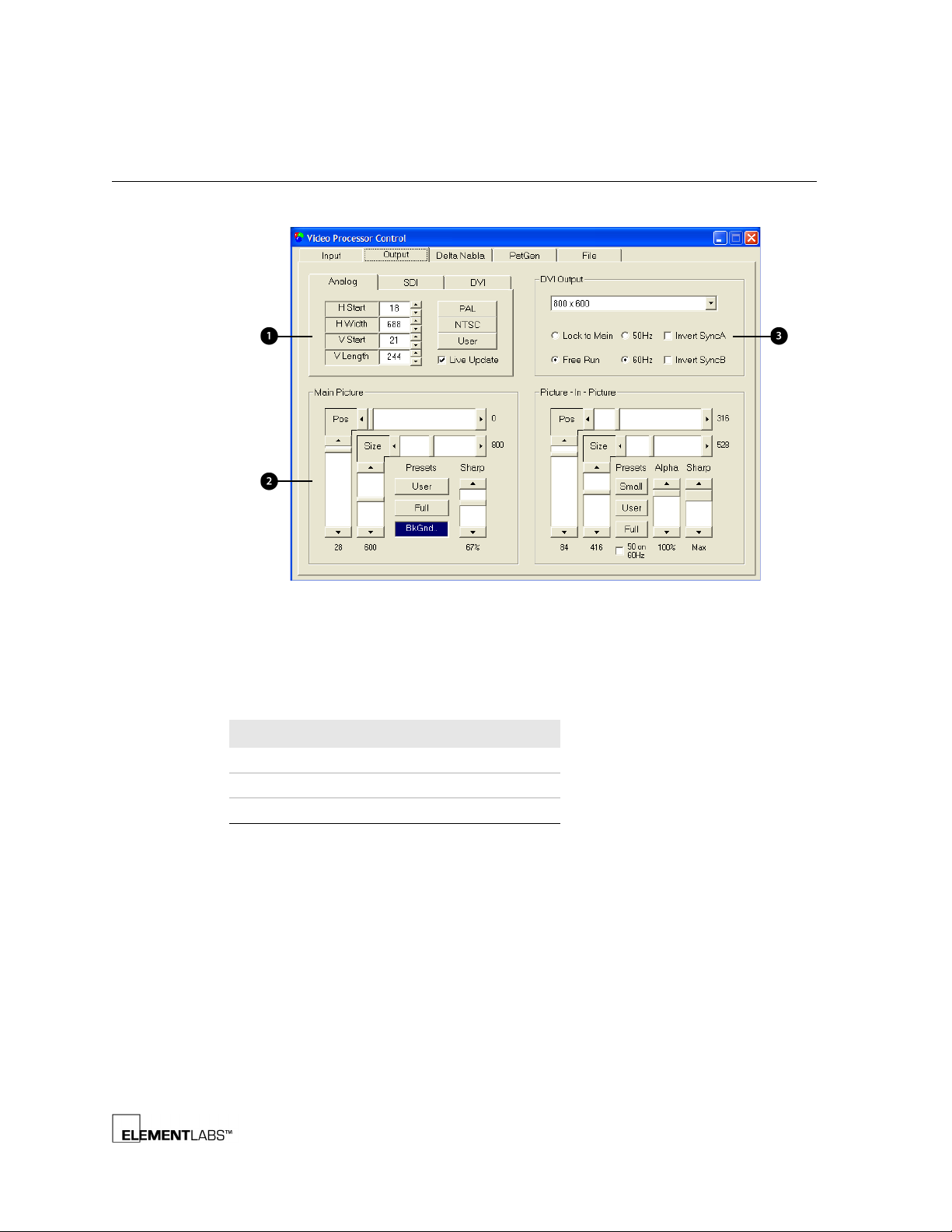
The LedGuru Output tab lets the user adjust output image parameters.
Appendix B
LedGuru Software
Figure 3.11
LedGuru Output Tab
The following table describes the PDB-3 front panel functionality:
Table 3.2
Legend # Item
PDB-3 Front Panel Connector Info
1 Input Cropping Adjustments
2Picture Scaling Adjustments
3DVI Output Adjustments
The Output tab is divided into three sections that are explained below.
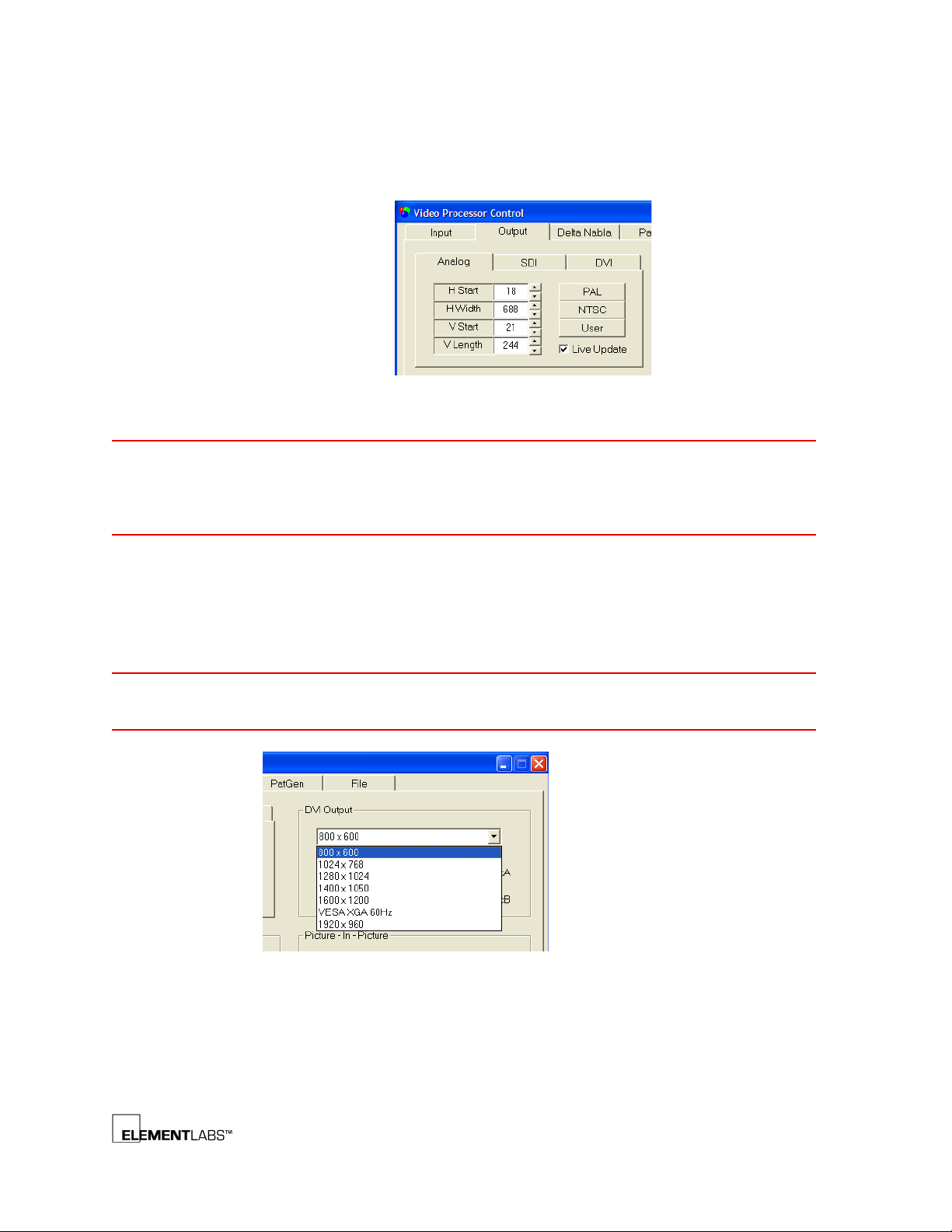
Input Cropping
Adjustments over which part of the input image is selected for output can be
accomplished in the Input Cropping section of the Output tab. For example, you
can crop off the black bands at the top & bottom of certain input video images.
STEALTH® v2 User’s Guide B-4
Page 44
Appendix B
www.shsglobal.store
LedGuru Software
The PAL and NTSC buttons can be used to set default crop values for these input
sources.
NOTE
NOTE
Figure 3.12
LedGuru Input Crop Settings
Care should be taken to ensure that you do not attempt to select an area which is
outside the boundaries of the input image since this will cause a corrupt output.
Make sure that if you increase VStart you also reduce VLength to ensure the
selected image area remains within the input image area.
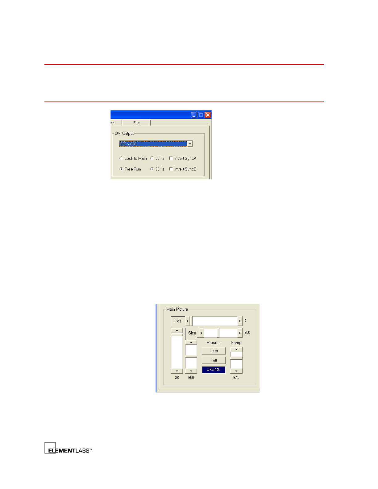
DVI Output
The DVI Output drop down can be used to select various DVI output modes. The
SP1 requires a 1024x768 signal. The other modes are provided for use with video
systems or displays.
The SP1 requires the Invert Sync box to be ticked on the output connected to the
SP1.
Figure 3.13
LedGuru DVI Output Settings
50 / 60 Hz Field Rates
The output field rate should typically be set to match the input field rate – and
Lock to Main should be selected. This ensures the best picture quality – with no
frame dropping or repetition.
STEALTH® v2 User’s Guide B-5
Page 45
Appendix B
www.shsglobal.store
LedGuru Software
NOTE
If the video input is changed from 50Hz to 60Hz you may at first see a juddering or
corrupt output. It is necessary to select the appropriate DVI Output field rate – to
match the input. Then update the Crop settings to match the input by clicking the
appropriate PAL or NTSC crop buttons.
Figure 3.14
LedGuru Field Rate Settings
Frame Rate Conversion
It is possible to convert between 50 and 60Hz output by selecting the Free Run DVI
output mode, then selecting either 50Hz or 60Hz output as required. In free-run
mode the VP1 will drop or repeat frames as necessary to match the input and
output field rates.
Picture Scaling
The size, position and sharpness of the output image can be adjusted using the
Main Picture Scaling section of the Output tab.
Clicking the Full button causes the image size to reset to fill the entire output
frame. Shift-clicking the User button saves the current size settings. Subsequently
clicking the button will recall the saved size settings.
Figure 3.15
LedGuru Picture Scaling Settings
STEALTH® v2 User’s Guide B-6
Page 46
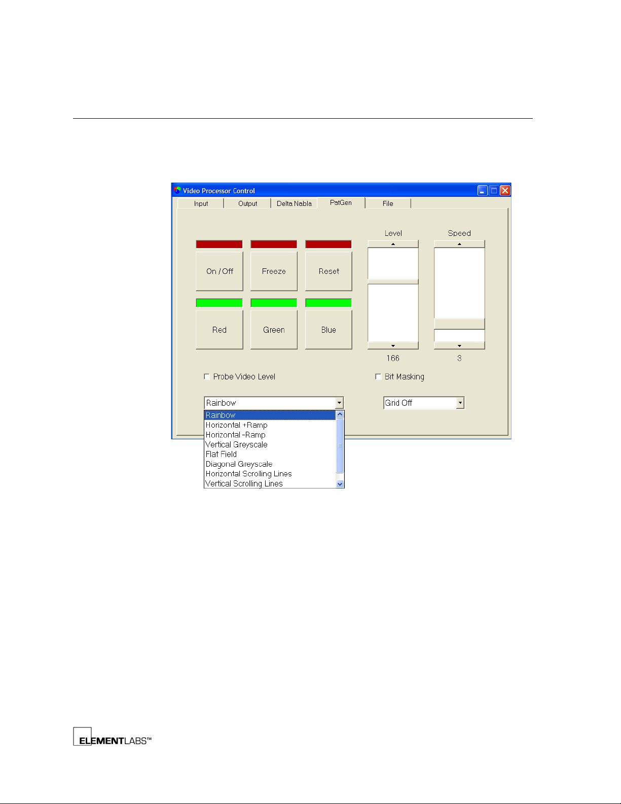
Pattern Generator
www.shsglobal.store
The internal pattern generator can be used to display various test patterns to help
identify and locate screen faults.
Most of the controls are self-explanatory.
Appendix B
LedGuru Software
Figure 3.16
When Probe Video Level is selected only the parts of the video image which have
an 8-bit video data value equal to the current Level slider setting will be displayed
at max video level (255). This allows the user to visually probe the video levels
being displayed on screen. This is useful when adjusting the video black level and
contrast controls since it shows if any parts of the output image are clipping (>255)
or if the black level is incorrectly set.
When Bit Masking is selected, the 8-bit video data is ‘ANDed’ with the Level slider
value before display. This allows the user to isolate single greyscale bits of video.
For instance, if Level is set to 128 and Bit Masking is selected, then only the MSB of
the incoming video signal will be displayed. This is useful to isolate faults which
only affect one greyscale bit within the video signal.
LedGuru Pattern Generator Tab
STEALTH® v2 User’s Guide B-7
Page 47
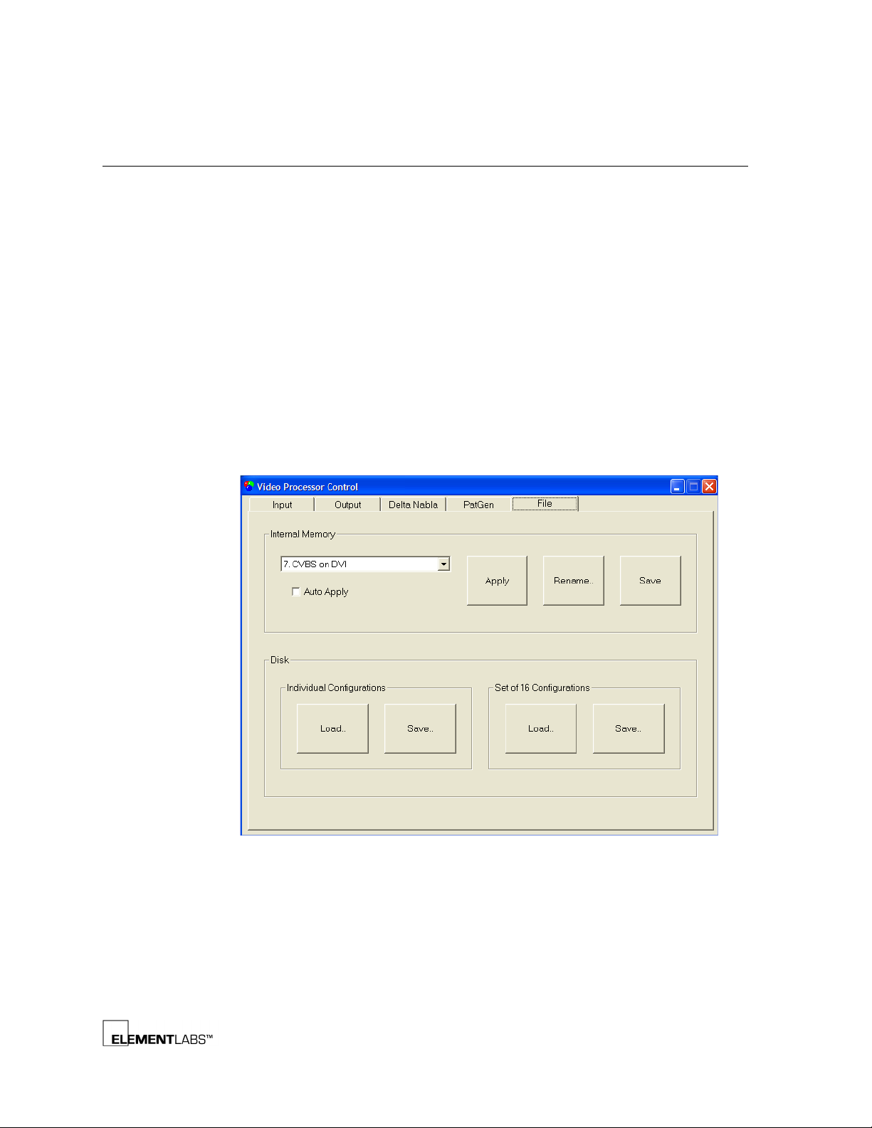
File Load Save
www.shsglobal.store
The File Load/Save page allows the user to load and save VP1 setups to disk or
internal memory.
The VP1 stores all settings and adjustments in an active internal memory. This
memory is automatically restored when the VP1 boots up. All user adjustments are
automatically stored in the active memory.
The VP1 also provides 16 internal memory slots. These can be used to store
complete VP1 setups for later recall. The LedGuru internal memory frame allows
the user to manage these memories.
The current active memory settings can be saved to the currently selected internal
memory slot by clicking Internal Memory / Save. This will overwrite any existing
settings stored in the memory slot.
When Apply is clicked the currently selected internal memory is copied into the
active memory – overwriting any existing settings in the active memory.
Appendix B
LedGuru Software
Figure 3.17
The current active memory settings can be individually saved or loaded to/from
disk. In addition complete sets of 16 internal memory configs can be loaded and
saved from/to disk.
LedGuru File Tab
STEALTH® v2 User’s Guide B-8
Page 48

A PPENDIX
www.shsglobal.store
Appendix C
A
PPLICATION
This chapter offers you some hints and notes on using STEALTH. The following
information is discussed:
N
OTES
• SP1 Vertical Offset
, (p. C-2)
STEALTH® v2 User’s Guide C-1
Page 49

SP1 Vertical Offset
www.shsglobal.store
The SP1 provides 2 fiber outputs, each with a resolution of 1024x256. The vertical
offsets for each fiber output port is limited by the lowest offset of it’s corresponding
DD1 output channel. Vertical offsets are changed via the SP1 front panel menus.
If any of the DD1 channels are set to a vertical offset of 0, whether they are used or
not, that fiber output will only display the first 256 vertical pixels. In order to move
the fiber output down to the 257th pixel or lower, all corresponding DD1 output
channels must be offset as well via the SP1 front panel menus.
For example, a 19 panel high screen should use the following SP1 settings:
Menu Item Settings Notes
DD1 Image Offset 0,0
CH 1-1 0, 0 panels 1-5
CH 1-2 0, 80 panels 6-10
CH 1-3 0, 160 panels 11-15
CH 1-4 0, 0 unused
CH 1-5 0, 0 unused
CH 1-6 0, 0 unused
CH 2-1 0, 240 panels 16-19
CH 2-2 0, 240 unused, but must be set to move fiber output
CH 2-3 0, 240 unused, but must be set to move fiber output
CH 2-4 0, 240 unused, but must be set to move fiber output
CH 2-5 0, 240 unused, but must be set to move fiber output
CH 2-6 0, 240 unused, but must be set to move fiber output
Appendix C
Application Notes
For more information on the SP1, refer to SP1 – Signal Processing Unit
STEALTH® v2 User’s Guide C-2
, (p. 2-4).
Page 50

I
www.shsglobal.store
NDEX
Numerics
48VDC, 2-9
A
Aperture Ratio, A-7
B
Basic Signal Flow, 1-3
Bezel Color, A-7
Block Size, 2-7
Brightness, 2-4, 2-6
C
Cable Attachment, 3-3
CEE 17, 2-11
Change Data Mode (SP1), 2-4, 2-5
Cheeseborough Clamp, 3-3
Coaxial In, 2-14
Coaxial Out, 2-14
Colors, A-7
Com Mode, 2-7
Component, 1-2, 2-2, A-2
Component Video Input, 2-3
Composite, 1-2, 2-2, A-2
Composite Video Input, 2-3
D
Daisy-Chained, 3-9
Data Connection, 3-9
Data Input Cable, 3-5
Data Input Jack, 3-5
Data Output, 2-8, 2-12, 2-14
Data Supply Unit, 2-9
DC Output Panel, 2-9
DD1, 1-2, 2-4
Front Panel, 2-8
Rear Panel Connections, 2-8
Specifications, A-4
Digital Visual Interface (DVI), 1-2
Dimensions, A-2, A-3, A-4, A-5, A-6, A-7
Display Mode, 2-6
DSU, 1-3, 2-9, 2-12
Front Panel, 2-14
Signal and Control Connections, 2-15
DVI, 1-2, 2-2, 2-5
In, 2-3, 2-5
Monitor, 2-5
Out, 2-3, 2-5
DVI-D, 2-2
E
EU 240V Power, 2-11
F
Fiber In, 2-8
Fiber Optic, 2-8
Fiber Optic Cable, 2-8
Fiber Out, 2-5, C-2
Flashing Red LED, 2-8
Folding STEALTH Panels, 3-8
G
Gamma, 2-4, 2-6
Grip Lock, 3-3
Ground, 2-11
H
Hardware Components, 1-2
HD-SDI, 1-2, 2-2, A-2
HD-SDI Resolution, 2-2
Header Assembly, 3-3
Header Bar, 3-3
Header Details, 3-4
Hinge Assembly, 3-6
Hinge Connection, 3-7
Horizontal Adjustment, 3-3
Horizontal Offset, 2-6
Hot Legs, 2-11
I
IEC 60309, 2-11
L
LEDs, 2-2
Link, 2-8
Link Direction, 2-7
LTW Adaptor, 2-14
LTW Connector, 2-9, 3-5, 3-9
LTW Jack, 3-9
STEALTH® v2 User’s Guide IX-1
Page 51

M
www.shsglobal.store
Maximum Display Area, 2-8
Mounting Holes, 3-5
Multiple Headers, 3-3, 3-4
Multiple STEALTH Panels, 3-6
N
NEMA L6-30, 2-11, A-5
Nits, A-7
O
Offset, 2-4, 2-6
Output, A-7
Output A-F, 2-8
Output Resolution, 1-2
P
PC Com Mode, 2-7
PDB to STEALTH Power
Connections, 2-10
PDB-3, 1-3, 2-9
Front Panel, 2-9
Rear, 2-10
PDB-3 Specifications, A-5
Pigtail, 3-9
Pixel Pitch, A-7
Power and Data Distribution, 2-9
Power Connection, 2-10, 3-9
Power Input, 2-10
Power Input Cable, 3-5
Power Input Connector (PDB-3), 2-11
Power Input Jack, 3-5
Power Supplies, 2-10
Processing Components, 2-1
R
Relay Box, 2-8
Removable Power Supplies, 2-10
Resolution, A-7
RGB Video Input, 2-3
RGBS, 2-3
RS232, 2-3, 2-5
S
Scan Boards, 2-12
Screen Brightness, 2-4
SDI, 1-2, 2-2, 2-3, A-2
SDI Input, 2-3
SD-SDI, 1-2, 2-2, A-2
Select Item Mode (SP1), 2-4, 2-5
Sensor, 2-8
Serial Control, 2-2, 2-3
Serial Digital Interface Input, 2-3
Signal and Control Connections, 2-15
Signal Flow, 1-3
Signal Processing Unit, 2-4
Solid Red LED, 2-8
SP1, 1-2, 2-4, 2-8
Cascade, 2-6
Front Panel, 2-4
Front Panel Buttons, 2-5
ID, 2-6
Menus, 2-6
Rear Panel Connections, 2-5
Setup Menus, 2-4
Specifications, A-3
Version, 2-7
Vertical Offset, C-2
Speakon Connectors, 2-9
Specifications, A-1
DD1, A-4
PDB-3, A-5
SP1, A-3
STEALTH Panel, A-7
VP1, A-2
ST Connector, 2-8
STEALTH
Header, 3-3
Header Details, 3-4
Panel, 1-2, 1-3, 2-12, 3-2, 3-5
Panel Specifications, A-7
System, 1-2, 1-3, 2-1
System Specifications, A-1
S-Video, 1-2, 2-2, A-2
Sync, 1-2
System Information, 2-7
STEALTH® v2 User’s Guide IX-2
Page 52

T
www.shsglobal.store
Test Pattern (DSU), 2-6
Test Patterns, 2-4
Transparency, A-7
U
US 120/208V Power, 2-11
V
v2.5 Hinge, 3-3, 3-6
Vertical Offset, 2-6, C-2
Vertical Sync, 1-2
Video Input Signal Formats, 1-2
Video Processing Unit, 2-2
Video Signals, 2-2
VP1, 1-2, 2-2
Front Panel, 2-2
LEDs, 2-2
Rear Panel, 2-3
Specifications, A-2
Video Signal Input Types, 2-2
W
White Balance, 2-7
X
XLR Connector, 2-14
Y
Y, Pr (R-Y), Pb (B-Y), 2-3
Y/C Video Input, 2-3
STEALTH® v2 User’s Guide IX-3
 Loading...