

Page 1

Page 2
FCC compliance statement
This device complies with part 15 of the FCC rules. Operation is subject to the following two conditions: (1) This device
may not cause harmful interference, and (2) this device must accept any interference received, including interference
that may cause undesired operation.
NOTE: This equipment has been tested and found to comply with the limits for a Class B digital device, pursuant to
Part 15 of the FCC Rules. These limits are designed to provide reasonable protection against harmful interference in
a residentpial installation. This equipment generates, uses and can radiate radio frequency energy and, if not installed
and used in accordance with the instructions, may cause harmful interference to radio communications. However,
there is no guarantee that interference will not occur in a particular installation. If this equipment does cause harmful
interference to radio or television reception, which can be determined by turning the equipment off and on, the user
is encouraged to try to correct the interference by one or more of the following measures:
• Reorient or relocate the receiving antenna.
• Increase the separation between the equipment and receiver.
• Connect the equipment into an outlet on a circuit different from that to which the receiver is connected.
• Consult the dealer or an experienced radio/TV technician for help.
European Union regulation compliance statement
This product has been tested to comply with the 2004/108/EC EMC Directive and the 72/23/EC Low Voltage directive.
his symbol indicates that your product must be disposed of properly according to local laws and regu-
T
lations.
The included switched-mode power supply is CEC Level IV compliant.
The device contains a non rechargable lithium perchlorate battery cell that may need to be recycled separately depending on local environmental laws. If the battery needs replacing, please contact Elektron or a local professional
technician for servicing.
Page 3

INTRODUCTION...........................................................................................................1-1
CONVENTIONS IN THIS MANUAL..................................................................................................... 1-1
THE PHILOSOPHY OF THE MONOMACHINE ...........................................................1-2
KEEP IN MIND .................................................................................................................................... 1-2
IGHLIGHTS....................................................................................................................................... 1-2
H
USER INTERFACE AND CONNECTORS....................................................................1-3
FRONT / MAIN CONTROL PANEL ..................................................................................................... 1-3
KEYBOARD INTERFACE, SFX-6........................................................................................................ 1-5
REAR CONNECTORS ........................................................................................................................ 1-6
ADDITIONAL REAR CONNECTORS, SFX-6...................................................................................... 1-7
RACK MOUNT KIT (SFX-60MKII ACCESSORY)................................................................................ 1-7
RACK MOUNT KIT ASSEMBLY..................................................................................................... 1-7
CONNECTING THE UNIT ................................................................................................................... 1-7
CARE INSTRUCTIONS ....................................................................................................................... 1-8
THE LCD USER INTERFACE ......................................................................................1-9
LAYER EDIT AND WINDOWS ............................................................................................................ 1-9
QUICK START ............................................................................................................1-10
SELECTING AND PLAYING A PATTERN......................................................................................... 1-10
LAYING IN MULTI TRIG MODE...................................................................................................... 1-11
P
EXPLORING A PATTERN ................................................................................................................. 1-11
DIFFERENT TYPES OF RECORDING............................................................................................. 1-11
OVERVIEW OF GRID RECORDING MODE................................................................................ 1-11
OVERVIEW OF LIVE RECORDING MODE ................................................................................. 1-12
PARAMETER LOCKS .................................................................................................................. 1-12
MONOMACHINE OVERVIEW ....................................................................................1-14
CHOOSE YOUR WAY OF WORKING............................................................................................... 1-14
SIX INDIVIDUAL TRACKS ........................................................................................................... 1-14
SIX TRACK SEQUENCING.......................................................................................................... 1-14
MIDI SEQUENCING ..................................................................................................................... 1-14
POLY MODE................................................................................................................................. 1-14
MULTI TRIG MODE...................................................................................................................... 1-14
MULTI MAP MODE....................................................................................................................... 1-14
MONOMACHINE SYNTHESIS ARRANGEMENT......................................................1-16
MONOMACHINE KITS ...................................................................................................................... 1-17
HE LINK BETWEEN KITS AND PATTERNS................................................................................... 1-17
T
LOADING A KIT............................................................................................................................ 1-18
LOADING AN EMPTY KIT............................................................................................................ 1-18
SAVING AND NAMING A KIT ...................................................................................................... 1-18
UNDO KIT..................................................................................................................................... 1-19
COPY KIT ..................................................................................................................................... 1-20
CLEAR KIT ................................................................................................................................... 1-20
KIT EDITING...................................................................................................................................... 1-21
ASSIGNING A MACHINE TO A TRACK ...................................................................................... 1-21
COPY MACHINE .......................................................................................................................... 1-22
CLEAR MACHINE ........................................................................................................................ 1-23
SETTING THE MIX BUS .............................................................................................................. 1-23
PARAMETER EDITING ..................................................................................................................... 1-24
TRACK EFFECTS ......................................................................................................1-25
LEVEL................................................................................................................................................ 1-25
MPLIFICATION PAGE..................................................................................................................... 1-25
A
1 of 6
Page 4

AMPLIFIER ENVELOPE............................................................................................................... 1-25
DISTORTION................................................................................................................................ 1-26
TRACK VOLUME.......................................................................................................................... 1-27
PAN............................................................................................................................................... 1-28
PORTAMENTO............................................................................................................................. 1-28
FILTER PAGE .................................................................................................................................... 1-28
BASIC FILTER CONTROLS......................................................................................................... 1-29
FILTER ENVELOPE ..................................................................................................................... 1-30
FILTER TRACKING ...................................................................................................................... 1-30
EFFECTS PAGE................................................................................................................................ 1-31
EQ................................................................................................................................................. 1-31
SAMPLE RATE REDUCTION....................................................................................................... 1-31
DELAY .......................................................................................................................................... 1-32
LOW FREQUENCY OSCILLATORS.......................................................................... 1-34
LFO CONTROLS .......................................................................................................................... 1-34
ADDITIONAL KIT SETTINGS ....................................................................................1-37
ASSIGN ............................................................................................................................................. 1-37
OYSTICK .................................................................................................................................... 1-38
J
VELOCITY .................................................................................................................................... 1-38
KEY TRACKING ........................................................................................................................... 1-39
TRIG TRACK SETTINGS .................................................................................................................. 1-39
MULTI TRIG....................................................................................................................................... 1-40
MULTI ENV........................................................................................................................................ 1-42
THE PATTERN SEQUENCER.................................................................................... 1-44
BASIC PATTERN OPERATION......................................................................................................... 1-44
PATTERN SELECTION ................................................................................................................ 1-44
PATTERN CHAINING ................................................................................................................... 1-45
SCALE SETUP ............................................................................................................................. 1-45
COMPOSING A PATTERN ................................................................................................................ 1-46
RECORDING PREPARATIONS ................................................................................................... 1-46
GRID RECORDING ...................................................................................................................... 1-46
LIVE RECORDING ....................................................................................................................... 1-48
STEP RECORDING...................................................................................................................... 1-49
NOTE COPY................................................................................................................................. 1-49
CLEAR NOTE PARAMETER LOCKS........................................................................................... 1-49
TRACK PAGE COPY.................................................................................................................... 1-50
CLEAR TRACK PAGE.................................................................................................................. 1-50
TRACK COPY............................................................................................................................... 1-51
CLEAR TRACK............................................................................................................................. 1-52
PATTERN COPY .......................................................................................................................... 1-52
CLEAR PATTERN......................................................................................................................... 1-53
SUPER COPY .............................................................................................................................. 1-53
SUPER CLEAR............................................................................................................................. 1-54
TEMPO .............................................................................................................................................. 1-54
THE TEMPO SCREEN ................................................................................................................. 1-55
TAP TEMPO ................................................................................................................................. 1-55
EXTERNAL SYNCHRONISATION ............................................................................................... 1-55
PARAMETER LOCKS........................................................................................................................ 1-56
PARAMETER LOCKS IN GRID RECORDING MODE ................................................................. 1-56
PARAMETER LOCKS IN LIVE RECORDING MODE .................................................................. 1-57
ADVANCED SEQUENCER CONTROL............................................................................................. 1-57
TRIG TRACKS.............................................................................................................................. 1-57
2 of 6
Page 5

TRIGLESS TRIGS ........................................................................................................................ 1-58
PITCHLESS TRIGS...................................................................................................................... 1-58
ADDITIONAL SEQUENCER FEATURES ..................................................................1-60
THE ARPEGGIATOR......................................................................................................................... 1-60
A
RPEGGIATOR BASIC SETTINGS ............................................................................................. 1-60
ARPEGGIATOR ENVELOPE TRIGGING SWITCHES................................................................. 1-61
ARPEGGIATOR RHYTHM AND OFFSET TRACK ...................................................................... 1-62
TRANSPOSE..................................................................................................................................... 1-62
SWING............................................................................................................................................... 1-63
THE SWING TRACK .................................................................................................................... 1-64
SLIDE ................................................................................................................................................ 1-65
THE MUTE MODE............................................................................................................................. 1-66
MINIMISING THE MUTE WINDOW ............................................................................................. 1-67
POLY MODE...................................................................................................................................... 1-68
THE MIDI SEQUENCER.............................................................................................1-69
USING THE MIDI SEQUENCER .................................................................................................. 1-69
HE MAIN MIDI SEQUENCER INTERFACE ............................................................................... 1-70
T
COMPARISON WITH THE INTERNAL SEQUENCER ................................................................ 1-70
THE SONG MODE......................................................................................................1-72
LOAD SONG ................................................................................................................................ 1-72
SAVE SONG................................................................................................................................. 1-73
SONG PLAY ................................................................................................................................. 1-74
SONG TRANSPORT .................................................................................................................... 1-74
SONG EDITING............................................................................................................................ 1-75
SONG EDIT TRANSPORT ........................................................................................................... 1-76
SONG LOOPS.............................................................................................................................. 1-77
SONG JUMP ................................................................................................................................ 1-77
SONG HALT ................................................................................................................................. 1-77
SONG TRACK TRANSPOSE ....................................................................................................... 1-78
SONG EXTRA .............................................................................................................................. 1-78
MONOMACHINE ROUTING.......................................................................................1-80
THE MONOMACHINE MIXER ..................................................................................................... 1-80
HE FX MACHINES ..................................................................................................................... 1-80
T
USING THE AUDIO INPUTS........................................................................................................ 1-81
NEIGHBOUR ROUTING .............................................................................................................. 1-82
MIX BUS ROUTING ..................................................................................................................... 1-83
ROUTING MODE AB=MIX ........................................................................................................... 1-84
ROUTING MODE 6xMONO ......................................................................................................... 1-84
GLOBAL SETTINGS ..................................................................................................1-86
TURBO MENU................................................................................................................................... 1-86
AUDIO ............................................................................................................................................... 1-87
MASTER TUNE ............................................................................................................................ 1-87
GLOBAL ROUTING...................................................................................................................... 1-87
CONTROL ......................................................................................................................................... 1-88
MIDI CHANNELS.......................................................................................................................... 1-88
MORE ON THE MONOMACHINE MIDI FUNCTIONALITY ......................................................... 1-89
CONTROL OUT1.......................................................................................................................... 1-90
CONTROL OUT2.......................................................................................................................... 1-91
CONTROL IN................................................................................................................................ 1-91
MULTI MAP EDIT ......................................................................................................................... 1-92
MECHANICAL SETTINGS (MKII UNITS ONLY)............................................................................... 1-93
3 of 6
Page 6

FILE ................................................................................................................................................... 1-94
SYSEX SEND ............................................................................................................................... 1-94
SYSEX RECEIVE ......................................................................................................................... 1-96
DIGIPRO MANAGER (MONOMACHINE SFX-60 MKII ONLY) ......................................................... 1-99
RECEIVE WAVEFORMS.............................................................................................................. 1-99
SEND WAVEFORMS.................................................................................................................. 1-101
ERASE WAVEFORMS................................................................................................................ 1-102
RENAME WAVEFORMS ............................................................................................................ 1-103
MIDI SEQ......................................................................................................................................... 1-104
MIDI SEQ SETTINGS ...................................................................................................................... 1-104
EARLY STARTUP MENU.........................................................................................1-106
TEST MODE .................................................................................................................................... 1-106
MPTY RESET................................................................................................................................ 1-106
E
FACTORY RESET ........................................................................................................................... 1-106
SOFT RESET .................................................................................................................................. 1-106
MIDI UPGRADE............................................................................................................................... 1-107
SEND UPGRADE ............................................................................................................................ 1-107
TECHNICAL INFORMATION ...................................................................................1-109
SPECIFICATIONS SFX-60MKII....................................................................................................... 1-109
DIFFERENCES BETWEEN THE MKI AND MKII MODELS .................................... 1-110
DESIGN ........................................................................................................................................... 1-110
POWER SUPPLY............................................................................................................................. 1-110
SNR RATIO AND OUTPUTS........................................................................................................... 1-110
CREDITS .................................................................................................................. 1-111
PRODUCT DESIGN AND DEVELOPMENT.....................................................................................1-111
INDUSTRIAL DESIGN ......................................................................................................................1-111
ADDITIONAL DESIGN......................................................................................................................1-111
USER’S MANUAL.............................................................................................................................1-111
FACTORY DEFAULT SOUND DESIGN ...........................................................................................1-111
FACTORY WAVEFORMS .................................................................................................................1-111
CONTACT INFORMATION....................................................................................... 1-112
ELEKTRON SUPPORT ................................................................................................................... 1-112
LEKTRON WEBSITE .................................................................................................................... 1-112
E
POSTAL ADDRESS......................................................................................................................... 1-112
APPENDIX A: MACHINE REFERENCE
SUPERWAVE............................................................................................................... A-1
SUPERWAVE SAW “SWAVE-SAW” ....................................................................................................A-1
SUPERWAVE PULSE “SWAVE-PULSE”.............................................................................................A-2
SUPERWAVE ENSEMBLE “SWAVE-ENS” .........................................................................................A-2
SID ............................................................................................................................... A-3
SID 6581 ..............................................................................................................................................A-3
DIGIPRO ...................................................................................................................... A-4
DIGIPRO WAVE “DPRO-WAVE” .........................................................................................................A-4
DIGIPRO BEAT BOX “DPRO-BBOX” ..................................................................................................A-4
DIGIPRO DOUBLEDRAW “DPRO-DDRW” .........................................................................................A-5
DIGIPRO ENSEMBLE “DPRO-DENS” ................................................................................................A-5
FM+.............................................................................................................................. A-6
FM+STATIC “FM+STAT” ......................................................................................................................A-6
M+PARALLELL “FM+PAR”................................................................................................................A-7
F
4 of 6
Page 7

FM+DYNAMIC “FM+DYN”...................................................................................................................A-7
VO ................................................................................................................................ A-8
VO-6 ....................................................................................................................................................A-8
V
O-6 TUTORIAL.............................................................................................................................A-9
GND MACHINES ....................................................................................................... A-10
GROUND “GND” ...............................................................................................................................A-10
SINE WAVE “SIN” ..............................................................................................................................A-10
NOISE “NOIS” ...................................................................................................................................A-10
FX MACHINES........................................................................................................... A-11
THRU................................................................................................................................................. A-11
EVERB ............................................................................................................................................ A-11
R
CHORUS ...........................................................................................................................................A-12
DYNAMIX ..........................................................................................................................................A-12
DYNAMIX TUTORIAL...................................................................................................................A-13
RING MODULATOR ..........................................................................................................................A-13
PHASER ............................................................................................................................................A-13
FLANGER..........................................................................................................................................A-13
APPENDIX B: MIDI CONTROL REFERENCE
MONOMACHINE MIDI SPECIFICATION .......................................................................................B-1
NOTE ON & NOTE OFF MESSAGES............................................................................................B-1
CONTROL CHANGE MESSAGES.................................................................................................B-2
NRPN MAPPING ............................................................................................................................B-5
OTHER MIDI MESSAGES .............................................................................................................B-6
APPENDIX C: SYSEX REFERENCE
INDEX
5 of 6
Page 8

6 of 6
Page 9

INTRODUCTION
INTRODUCTION
Thank you for choosing the Monomachine SFX-6/SFX-60/SFX-60MKII as your companion
for music creation. It is a powerful and intuitive tool for creating sounds, melodies and musical compositions of all kinds. We hope you will have a lot of fun while exploring the vast
possibilities of the Monomachine. To make the most of the SFX-6/SFX-60/SFX-60MKII, we
would like you to carefully read the relevant parts of this manual before operating the
instrument.
CONVENTIONS IN THIS MANUAL
In this manual we have used certain conventions for indicating input using knobs and but-
ons through the user interface. These conventions are listed below.
t
Keys (buttons) are written in upper case with bold style, and they are enclosed in brackets.
For instance, the key “function” on the main panel is written [FUNCTION].
Menu names, certain modes and operations are written in upper case. The SYNTHESIS
menu is an example of that.
Messages visible on the screen will be written in upper case with quotation marks. Like
this, “RECEIVING DUMP”.
Parameter abbreviations as they appear on the screen are written in bold style, for example PTCH
Knobs are written in upper case with bold, italic style. For instance, the LEVEL knob is an
example of this.
LED indicators like the record LED are written <RECORD>.
The following symbols are used throughout the manual:
This symbol indicates information that you need to pay attention to.
This symbol indicates a tip that might make it easier interacting with the SFX-6/
SFX60/SFX-60MKII.
This symbol is used to caution you to protect your hearing (once).
Monomachine SFX-6/SFX-60/SFX-60MKII USER’S MANUAL for operating system version 1.22. This manual (rev
) is copyright © 2001-2010 Elektron Music Machines MAV AB. All reproduction without written authorization is
F
strictly prohibited. The information in this manual may change without notice. Elektron’s product names, logotypes, titles, words or phrases may be registered and protected by Swedish and international law. All other brand
or product names are trademarks or registered trademarks of their respective holders.
1
Page 10

THE PHILOSOPHY OF THE MONOMACHINE
THE PHILOSOPHY OF THE MONOMACHINE
Synthesizers are available in many different types and forms. Nevertheless, for most part
they follow the norm how a synthesizer of its era is expected to be. Development for musical tools generally comes in the form of new synthesis techniques or an increase in polyphony, memory or other quantitative elements. The advances in the music machine world
have brought numerous good inventions for musicians. However, we believe usability is
easily lost in the hunt for the highest specifications.
With the Monomachine we have tried creating a synthesizer free from prejudice, and focus
on what actually spurs creativity without letting technology stand in your way. We want to
inspire you to make sounds and music you haven’t even thought of.
We have put all our efforts into exploring, to the fullest extent, the concept we believe is
one of the most creative in the history of synthesizers - the monophonic synthesizer with a
tightly integrated sequencer. The Monomachine offers ground breaking sound synthesis
machines, divided into five Monosynths, together with dedicated track effects. The sound
synthesis tracks are controlled with the world’s most advanced pattern based sequencer,
inspired by the concept found in grid programmed drum machines.
KEEP IN MIND
The Monomachine is a very multifaceted synthesizer. Depending on how you choose to
se it certain aspects of it will be more important to you. We have combined many new cre-
u
ative approaches with what we enjoy most in the tradition of synthesizers.
Try to find your own way of working, whether it being using the song sequencer to build
complete songs, building patterns for real-time manipulation using the MULTI TRIG function, or using your favourite sound in POLY mode. This user’s manual will guide you
through all the functions and give some hints on relevant applications.
HIGHLIGHTS
• 6 Track Internal Sequencer with sound synthesis
• 6 Track External MIDI Sequencer
• 5x Monosynths: SuperWave, SID, DigiPRO, FM+, VO
• Dynamically controlled Stereo effects.
• 6x Tape-style Tempo synced delays
• 18x Tempo synced LFO's
• Full real-time control
• User waveforms (SFX-60MKII only)
• Man-Machine potential
2
Page 11
USER INTERFACE AND CONNECTORS
&&&*&*&'&)&(
&,
&
,
-
.
&%
&-
+*)('
USER INTERFACE AND CONNECTORS
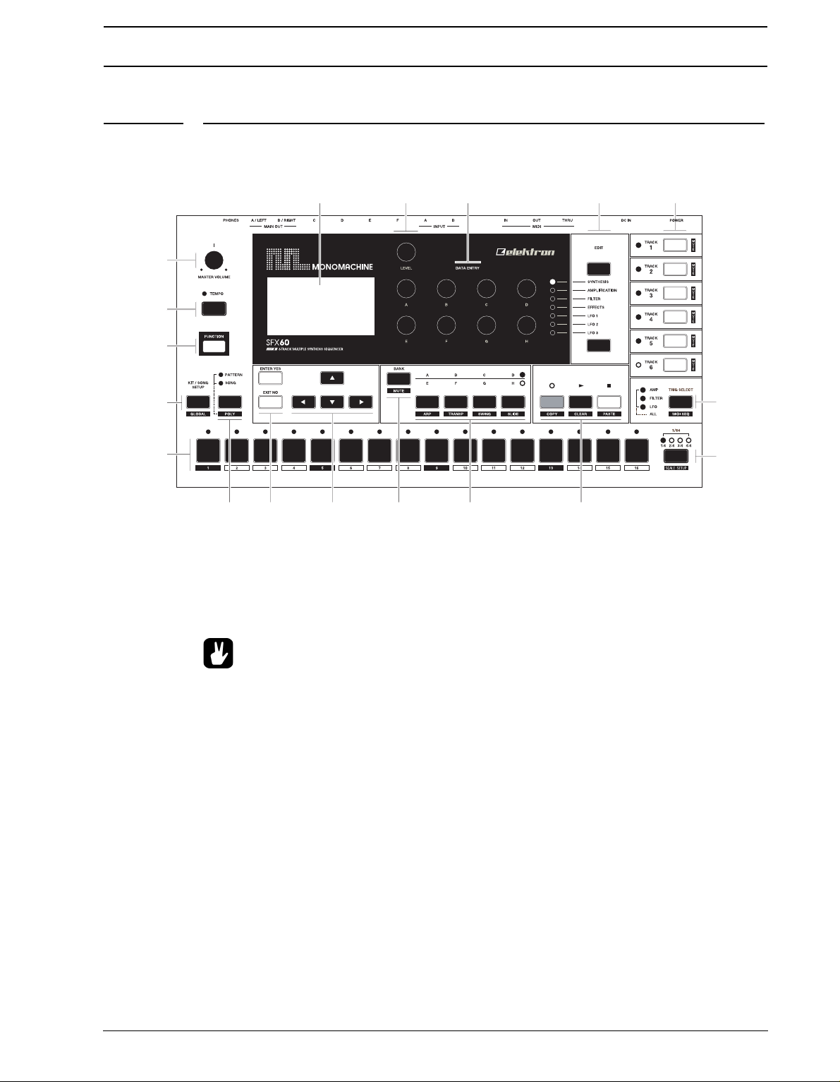
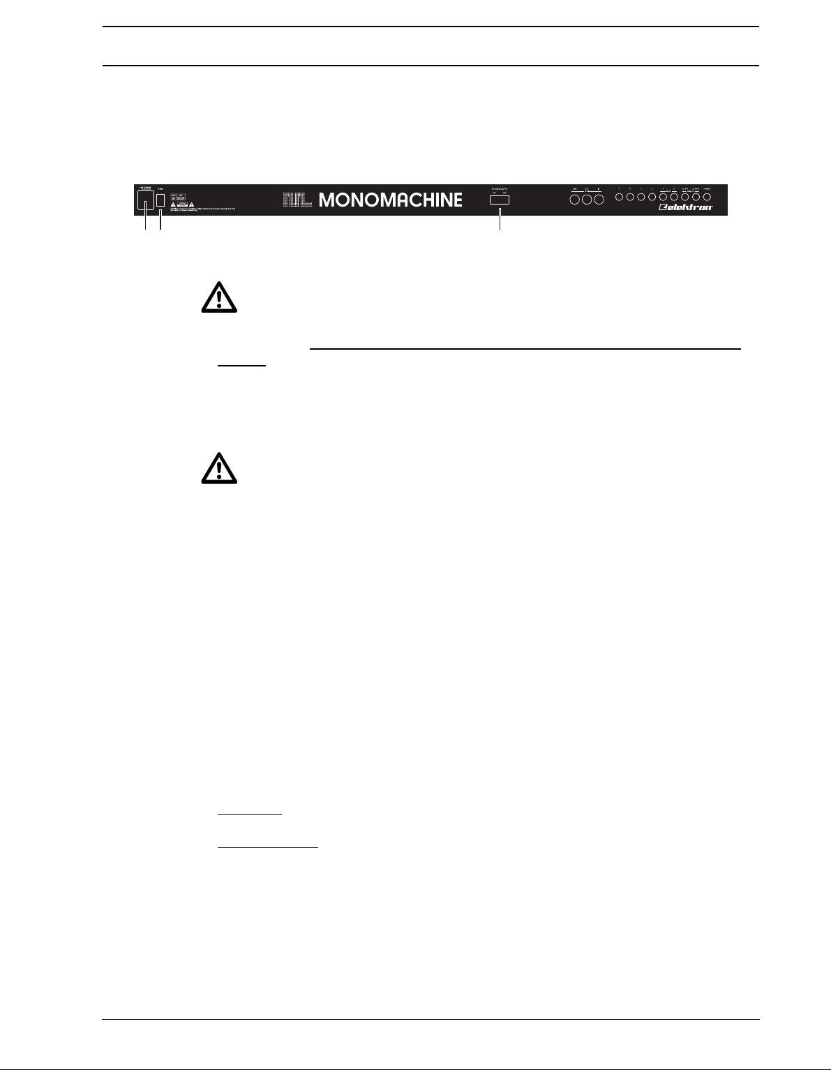
FRONT / MAIN CONTROL PANEL
The Monomachine SFX-60 MKII front panel / SFX-6 main control panel:
1. Master volume control. Sets the volume for the main output and the headphone jack.
2. The LCD graphical interface display.
3. LEVEL k
4. DATA ENTRY
nob. Sets the overall volume level of the track in focus.
knobs. Used for tweaking parameters for the machines and effects.
• The DATA ENTRY and LEVEL knobs allow accelerated editing by pressing the
knob while turning it.
5. [DATA PAGE] selection keys. These keys are used for browsing through the seven
DATA pages. The current selection is indicated by the <DATA PAGE> LED’s to the left of
these keys.
Press both [DATA PAGE] keys simultaneously to open the MULTI ENV window.
6. [TRACK] keys 1-6. These keys are used for selecting which track is in focus of editing.
The secondary function is to mute or activate the track. The <TRACK> LED’s are
located to the left of the [TRACK] keys. These indicate which tracks are active or muted,
and also which track is in the editing focus. The LED colours indicate the following:
Green = Active, Non-lit = Muted, Red = Active in focus, Yellow = Muted in focus
7. [TEMPO] key. Press to bring up the tempo window for adjustment. The current tempo is
always indicated by the speed of the flashing of the <TEMPO> LED. While holding
[FUNCTION] you can use [TEMPO] for tapping the tempo.
8. [FUNCTION] key. Press and hold it for accessing the secondary function of another key.
9. [KIT/SONG] k
ey. Opens the kit menu, or the song menu if in song mode. The secondary
function is calling the [GLOBAL] menu.
3
Page 12

USER INTERFACE AND CONNECTORS
10.[TRIG] k
eys 1 to 16. Main functions of these keys are as keyboard for trigging notes,
and for editing notes in GRID RECORDING mode. They are also used for choosing patterns, if pressed while holding one of the [BANK] keys. When functioning as a keyboard,
the notes are played with velocity 80. Hold [FUNCTION] while playing to play with full
velocity (127).
11.[PATTERN/SONG] key. Switches between pattern and song sequencer mode. The cur-
rent sequencer mode is indicated by the <PATTERN> and <SONG> LED’s. The secondary function is to set the unit in [POLY] mode.
12.[ENTER/YES] and [EXIT/NO] keys. Used for entering and exiting menus and for con-
firming choices or aborting functions.
13.The [
ARROW] keys. Used for menu navigation. The [ARROW] keys are individually
named [UP], [DOWN], [LEFT] and [RIGHT].
In the main interface screen [UP] and [DOWN] are used for setting the octave for the
[TRIG] keys.
14.[BANK GROUP] key. Used for switching between bank group A to D and E to H. The
<BANK GROUP> LED’s to the right indicate the current selection. The secondary function is to enter the dedicated [MUTE MODE].
15.[A/E], [B/F], [C/G] and [D/H] [BANK] keys. Hold one of the [BANK] keys and then
press one of the [TRIG] keys to select the pattern (A01-H16) indicated by the label of the
[BANK] key and the <BANK GROUP> LED’s. The secondary functions are to edit the
track settings for the arpeggiator and the transpose, swing and slide functions.
16.[REC], [PLAY], [STOP] keys. The [REC] key is used for toggling GRID RECORDING
mode on/off. [PLAY] Initiates playback of a pattern or song. Pressing [PLAY] a second
time pauses playback. Press [PLAY] while holding [REC] to enter LIVE RECORDING
mode. Press [REC] while holding [STOP] to enter STEP RECORDING mode. [STOP]
halts the playback of a pattern or song. Press [STOP] twice to rewind the song and turn
off all sound and reset various things. In GRID RECORDING mode, the <RECORD>
LED gives a steady light, in LIVE RECORDING it flashes and in STEP RECORDING
mode it double flashes. The secondary functions of these keys are to perform copy,
paste and clear commands.
17.[SCALE] k
ey. In GRID RECORDING mode: switches the track page focus of the [TRIG]
keys if the scale length exceed 16. The trig positions are organised in up to four pages
with 16 positions in each. The <TRACK PAGE> above the [SCALE] key indicate which
page is currently being edited or played. The secondary function is calling the SCALE
SETUP menu.
18.[TRIG SELECT] key. Switches which trig track is programmed from the [TRIG] keys.
The <TRIG TRACK> LED’s to the left indicate the current track selection. The secondary
function is to enter or exit the MIDI SEQ mode.
4
Page 13
USER INTERFACE AND CONNECTORS
1 2
3
4
5
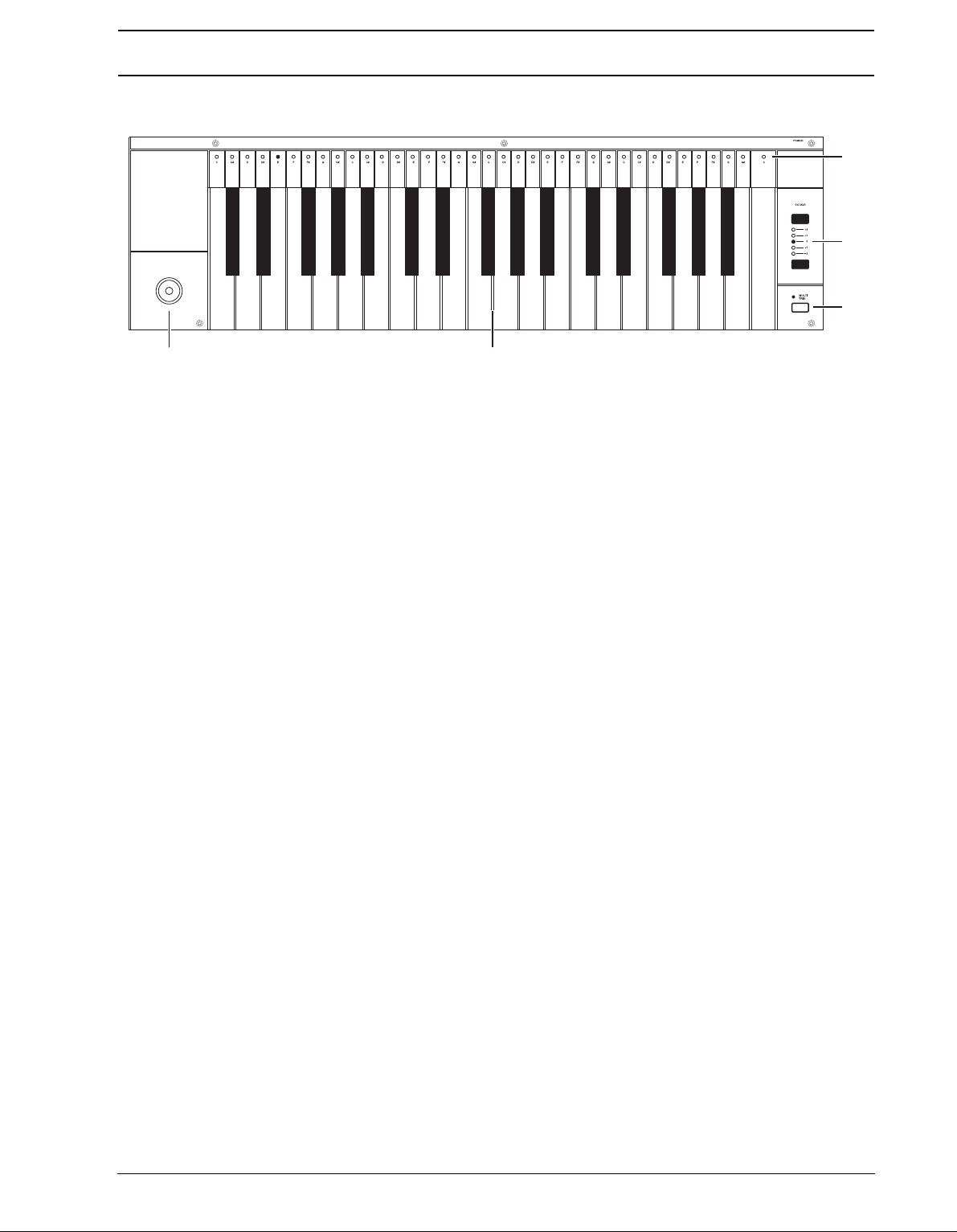
KEYBOARD INTERFACE, SFX-6
1. Joystick, for real-time expression control. The joystick can individually control parame-
ers for all tracks.
t
2. Keyboard, for real-time playing and for use in the GRID RECORDING and LIVE
RECORDING modes.
3. [MULTI TRIG] key, used for toggling the MULTI TRIG mode. The current state of the
MULTI TRIG mode is being indicated by the <MULTI TRIG> LED above. The secondary
function of this key is to toggle the MULTI MAP mode. MULTI MAP mode is indicated by
the <MULTI TRIG> LED flashing. Read more about these modes of operation in the section “MULTI TRIG” on page 40 .
4. [OCTAVE] keys. Control which octaves the keyboard is playing, and which notes are
represented on the <KEYBOARD> LED’s.
5. <KEYBOARD> LED’s. Shows the notes being played on the active track, or pro-
grammed on a step selected in GRID RECORDING mode.
5
Page 14
USER INTERFACE AND CONNECTORS
&
H;M"+%
',)+*(
H;M"+%B@>>
&,)+*('
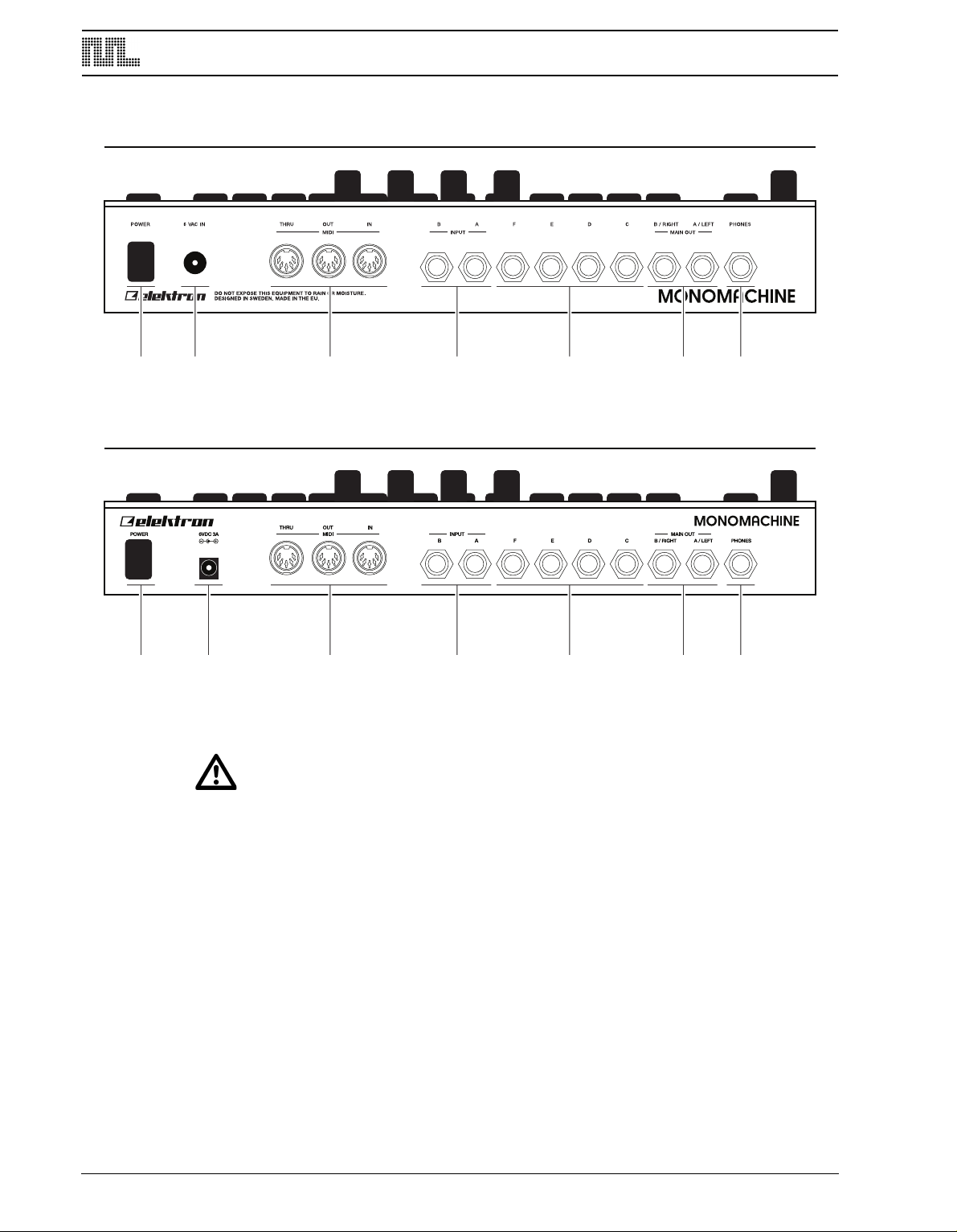
REAR CONNECTORS
1. Power On/Off switch.
2. Power in.
• Caution! Use only an Elektron-approved power supply with your Monomachine
SFX-60 MKII. It allows the unit to be used all over the globe without the need of
voltage converters. If you need a new power supply the specifications are 6VDC,
3A, 5.5x2.5mm (2.5mm inner diameter) DC power plug (power at center),
ungrounded 2 prong inlet (IEC320-C8). Using the wrong type of adapter may result
in damage to your unit. Damage caused by the use of incorrect power supply is
not covered by warranty. If you are unsure about your power supply, please contact Elektron support.
• Note that the MKI models require a different power supply compared to the MKII
models. Please see “DIFFERENCES BETWEEN THE MKI AND MKII MODELS” on
page 109 for detailed info about the specifications of the power supply that should
be used with the MKI models of the Monomachine SFX-60 MKII.
3. MIDI Thru/Out/In
4. Audio Input B/A
5. Individual Audio Outputs F/E/D/C
6
Page 15
USER INTERFACE AND CONNECTORS
1 2 3
6. Main/Individual Audio Outputs B/A
7. Stereo Headphone Outputs (Amplified copy of output AB)
ADDITIONAL REAR CONNECTORS, SFX-6
1. AC 115/230V 50/60Hz Input with integrated fuse holder and spare fuse storage.
• Caution! Although the Monomachine SFX-6 can accept both 115 and 230 Volts
main current, both the voltage selector and the fuse need to be matched to the
voltage. The fuse holder has two sections. The inner is the one currently in use.
For 115V operation the fuse should be specified as 250mA, 125V. For 230V operation the fuse should be specified as 125mA, 250V.
2. Power On/Off switch.
3. Voltage selector.
• Caution! If you want to change the voltage for the Monomachine, please take
notice of the warning found in the first point of this section.
RACK MOUNT KIT (SFX-60MKII ACCESSORY)
The Monomachine SFX-60MKII can be rack mounted in a standard 19” rack, using the
SFX-60/SPS-1 rack mount kit which is ordered separately. When rack mounted, the SFX60 MKII occupies four standard height units plus additional space needed to accommodate
cables plugged into the unit at the back.
RACK MOUNT KIT ASSEMBLY
Make sure that you use a Philips screwdriver of the right size, and in good condition. Use
the included M3x6mm size screws to secure the rack mount consoles on each side of the
SFX-60 MKII. Make sure that all screws are fastened for secure operation of the unit.
CONNECTING THE UNIT
Follow the basic guide below to power up your unit for the first time.
1. For SFX-6
voltage selector on the back of your SFX-6.
For SFX-60MKII: Connect the supplied DC adapter to a wall socket, and connect the
small plug into the rear of the unit.
2. Connect the Main Audio Out A/B from the Monomachine to your mixer or amplifier, and/
or connect a pair of stereo headphones to the Headphone Output.
3. If MIDI control is desired, connect the MIDI OUT from the Monomachine to the MIDI IN
of the device you wish to send data to. Connect the MIDI IN of the Monomachine to the
MIDI OUT of device you wish to receive data from. The MIDI THRU port is “echoing” the
data coming in from the MIDI IN port, so it can be used for daisy chaining other MIDI
units.
: Insert the supplied power cord in a grounded wall socket, specified as the
7
Page 16

USER INTERFACE AND CONNECTORS
4. Switch all units on.
5. If you do not have any previous experience of the Monomachine we suggest that you fol-
ow the “QUICK START” on page 10.
l
CARE INSTRUCTIONS
To ensure many years of trouble free operation, please follow the advice below:
• Never use any aggressive cleaners on the casing or the LCD overlay. Remove
dust, dirt and fingerprints with a soft dry cloth. More persistent dirt can be
removed with a slightly damp cloth using only water.
• Never use sharp objects near the display to avoid scratches or damage. Also
void applying any pressure to the display itself.
a
• When transporting the Monomachine, try to use the box in which it was originally
shipped with the padding supplied, or equivalent packaging.
• Make sure that you place the unit on a stable surface before use. If you mount the
unit in a rack, be sure to tighten all four screws in the rack mount holes.
• The memory used for storing patches and kits is powered by a battery inside the
unit. It will hold data for at least 6 years before needing replacement. If the battery
needs replacement, the “BATTERY LOW” message will appear in the display. Contact Elektron support or your nearest repair center.
• Turn off the machine when not in use.
8
Page 17
THE LCD USER INTERFACE
THE LCD USER INTERFACE
The center of the Monomachine SFX-6/SFX-60MKII editing is the LCD graphical interface
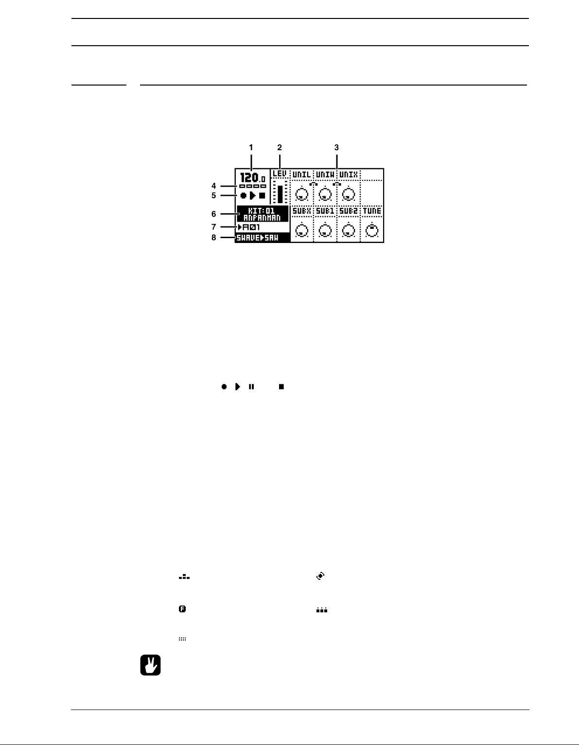
display. The interface screen for the SYNTHESIS page is printed below:
1. The current tempo. This will show “EXT” when synced to external tempo.
2. Level bar showing the selected volume level of the machine on the track in focus.
3. Up to eight parameters. They correspond to the layout of the 8 D
The little dot in the circle indicates the current parameter value. If an knob isn’t represented it means it serves no function at that particular screen. Above the graphical representation of the knobs are up to four characters, the abbreviation for the parameter the
knob controls.
4. Four rectangular boxes showing the playback position in the pattern page.
5. The playback/recording status shown by the standard “record”, “play”, “pause” and
“stop” symbols; , , and .
6. Name and number of the current kit.
7. The index of the current pattern, ranging from A01 to H16.
8. Specification of the Mono-synth and machine of the track in focus.
ATA ENTRY knobs.
LAYER EDIT AND WINDOWS
When a function which puts a window on top of the main interface screen is opened, the
unction of certain buttons and/or knobs will change. The buttons that are not used or
f
blocked can still be used to control the layer underneath. For example, when you have
called the tempo function it will make use of the LEVEL knob, but you can still use the
DATA ENTRY knobs to control the track in focus. When a window has functions mapped to
such interface controls, help is provided at the bottom of the window in the form of icons
representing these controls. The icons are:
The arrow buttons The LEVEL knob
The [FUNCTION] key The [TRIG] keys
The DATA ENTRY knobs
• All windows can be closed using the [EXIT/NO] key.
9
Page 18
QUICK START
QUICK START
This quick start will guide you through some of the basic operations to get you started using
the Monomachine. First connect your unit as described in section “CONNECTING THE
UNIT”, on page 7.
• The DATA ENTRY knobs have accelerated editing when being pressed. By default,
the knobs increase/decrease the parameter value in steps of +1/-1. When pressed,
the step length is higher, allowing quicker adjustments.
This guide assumes you have a Monomachine SFX-6 Keyboard or SFX-60MKII tabletop
module with a MIDI keyboard connected. If you have a SFX-60MKII you need to take care
to set the midi keyboard to play on the correct MIDI channel. When we refer to play a
sound in MULTI TRIG mode, a MIDI keyboard should be sending on the multi trig channel.
By default this is set to MIDI channel 7. When playing on a specific track we recommend
using the auto track channel which will switch focus depending on which track is selected
with the [TRACK] keys. By default the auto channel is assigned to MIDI channel 9. Please
refer to section “MIDI CHANNELS”, on page 88 for more information on the MIDI channel
assignment of the Monomachine.
SELECTING AND PLAYING A PATTERN
1. Verify that the <PATTERN> LED is lit and the <SONG LED> is not. If this isn’t the case,
press the [PATTERN/SONG].
2. Check the <BANK GROUP> LED to see if bank group A-D or E-H is active. If needed
press [BANK GROUP] key to toggle the active bank group. For this demonstration use
group A-D.
3. To select pattern A01, press and hold the pattern selection key [
[TRIG] key 1. You can see the index of the currently selected pattern in the lower left
corner of the display. Each pattern automatically loads the kit it is linked with. The name
of the kit is also shown in the display.
4. To listen to the pattern, press the [PLAY] key. The pattern starts playing and loops back
to the beginning again when it has reached its end. Pressing [PLAY] while playing
pauses the playback.
5. To change patterns during playback, simply select a pattern the same way as in step 3.
The display will show the selected pattern next to the current one, but with an arrow
pointing between them. This indicates that once the current pattern has played to its
end, the new selected pattern will start playing.
6. To stop the playback of the pattern, press the [STOP]
key.
A/E] and then press the
10
Page 19

QUICK START
PLAYING IN MULTI TRIG MODE
1. Select a pattern, ranging from A01-D16. All the Monomachine presets are located in this
ange. Make sure the sequencer is stopped.
r
2. Enter MULTI TRIG mode. On SFX-6 press the [MULTI TRIG] key and check that the
<MULTI TRIG> LED is lit with a steady light. For SFX-60 MKII select the multi trig channel on your MIDI keyboard.
3. Play some notes!
4. Depending on the trig mode selected in the kit a number of things could happen. Please
refer to section “MULTI TRIG”, on page 40 for the full story.
EXPLORING A PATTERN
1. Select a pattern as previously described.
2. Make sure the sequencer is stopped and that MULTI TRIG mode is switched off on the
FX-6 (<MULTI TRIG> LED not lit) and that the sequencer is not in GRID RECORDING
S
mode (<REC> LED not lit). Use the auto channel if using an external MIDI control keyboard.
3. Select one of the six tracks as the active track by pressing a [TRACK] key.
4. For each track the machine loaded is displayed in the lower left corner of the display.
5. Play some notes on each of the tracks, either using the keyboard or the [TRIG] keys.
Note that it’s possible that not all tracks will sound, the track can be an FX that needs
input from another track or silenced due to the output assigning, machine selection or
track effect settings. If you don’t hear anything, try selecting another track.
6. Use the [DATA PAGE] keys to navigate between the DATA pages. The <DATA PAGE>
LED’s will indicate the current selection. Select the SYNTHESIS page.
7. Now, turn any of the DATA ENTRY knobs to tweak the machine synthesis parameters
on the selected track. You can change any parameters without fear of losing presets or
other kits stored, as the changes will not be saved if you don’t save the kit. The parameters presented on the SYNTHESIS page are specific to the machine loaded. See Appendix A for information about the parameters and functions of the machines.
8. Use the [DATA PAGE]
FILTER and EFFECTS pages and explore the wide range of sound shaping tools available. You can find information about the track effects on page 25.
keys to continue to the DATA pages named AMPLIFICATION,
DIFFERENT TYPES OF RECORDING
OVERVIEW OF GRID RECORDING MODE
You can input notes into a pattern of the sequencer, both while the sequencer is running
and when it is stopped. First select the pattern you wish to edit. You might want to select an
empty pattern, as all changes are made “live” to the pattern. As factory default, patterns
E01-H16 are empty.
1. If you wish you can change the kit assigned to the pattern by, press the [KIT] key, then
select LOAD in the menu, and select the kit you prefer from the list presented.
2. Press the [RECORD] key to enter GRID RECORDING mode. The <RECORD> LED
should be firmly lit.
11
Page 20
QUICK START
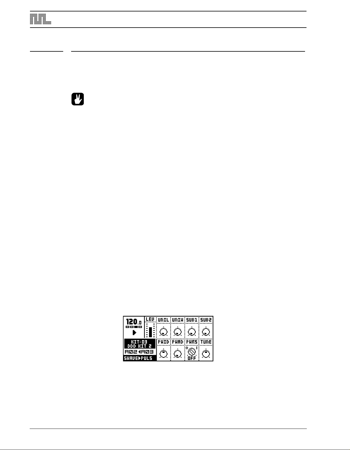
3. Choose to active a track using the [TRACK]
keys. Below is a screen shot of how the
SYNTHESIS page could look like after selecting a track.
4. Press a [
TRIG] key to add a note trig. A note trig is indicated by a red <TRIG> LED.
Pressing the same [TRIG] key once more removes the note trig.
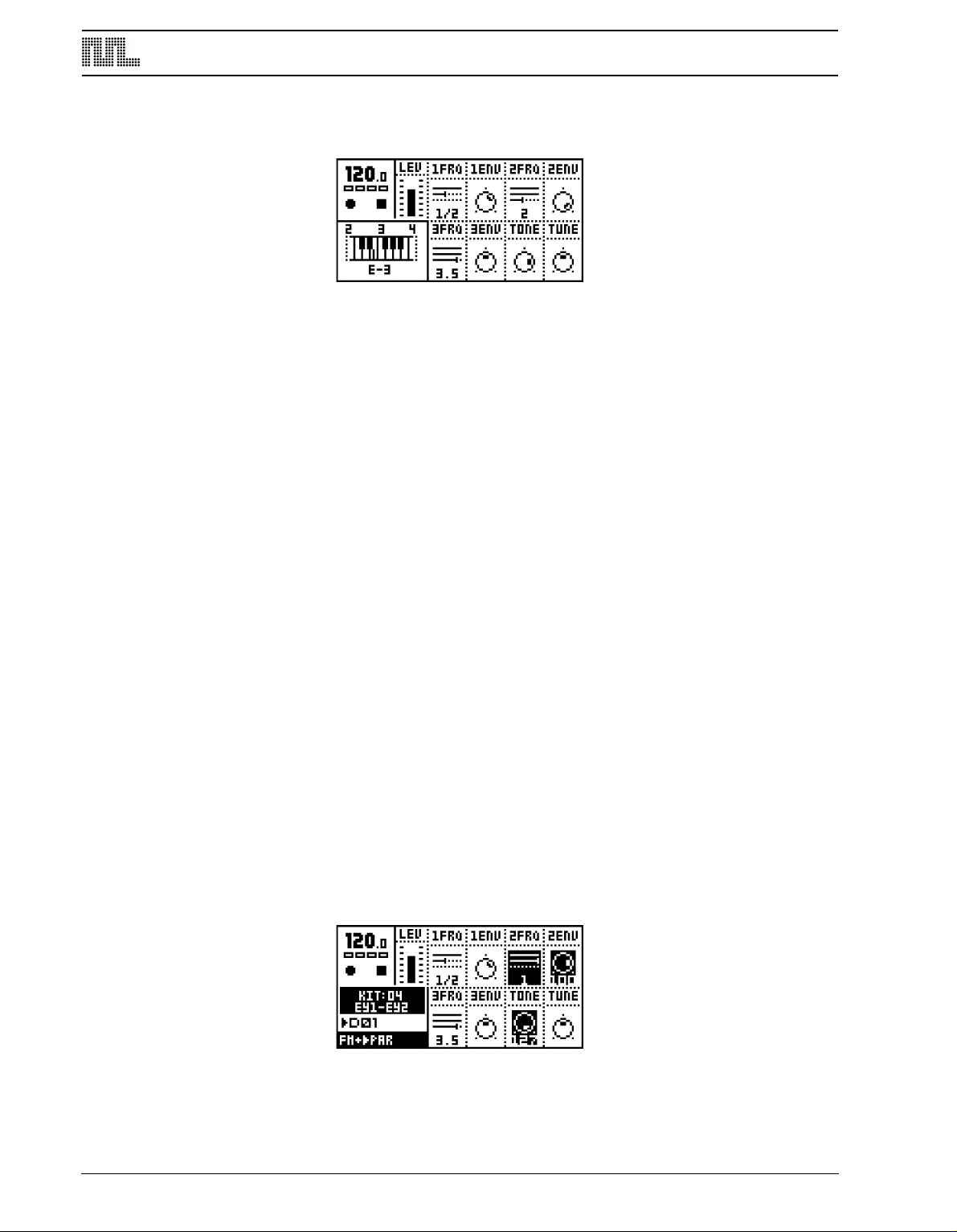
5. To change the pitch of a note, press and hold the [TRIG] key. You will see a mini key-
board pop up in the lower left corner of the screen. Either input the new note on the keyboard or use the [ARROW] keys to select the new note. When done release the [TRIG]
key.
6. To enter a note off trig, press a [TRIG] key while holding the [FUNCTION] key. A Note
Off is indicated by a yellow <TRIG> LED. To remove a note off the same [TRIG] key
must be pressed twice.
OVERVIEW OF LIVE RECORDING MODE
The LIVE RECORDING mode allows you to record notes in real-time while the pattern is
playing.
To enter this mode, press and hold [RECORD] and then [PLAY].You can now play notes on
the track you want to record, using either the [TRIG KEYS] or a keyboard. All played notes
will be quantised to the closest trig step.
If a note is played on a position where there already was a note programmed the new note
will replace the note on that step.
To erase notes in LIVE RECORDING mode hold [EXIT/NO] while the notes you want to
remove are heard.
The pattern will loop and be ready for further recording until you press the [STOP] key.
PARAMETER LOCKS
A parameter lock is a parameter locked to a certain value for a specific step. Parameter
locks can be programmed in GRID RECORDING mode and recorded in LIVE RECORDING mode. Parameter locks are a very important part of creating unique and dynamic patterns.
12
To lock parameters on a specific step in the track in GRID RECORDING mode, hold a
[TRIG] key and turn or click a DATA ENTRY knob. The parameter connected to the knob
will be inverted to indicate that it now is has a parameter lock. The corresponding <TRIG>
LED will flash rapidly to indicate that a parameter is locked for that step.
Page 21

QUICK START
In LIVE RECORDING mode, you can lock parameters by turning a knob while recording.
Parameters can be locked for any parameter and track. To lock parameters for a new track,
select that track with the [TRACK] button and repeat the steps above.
To remove a single lock in GRID RECORDING mode, press and hold the [TRIG] key and
click the knob connected to the parameter you wish to remove. You will see that the
inverted square around the parameter is removed. To remove all parameter locks for a trig,
hold the [TRIG] key and press [CLEAR]. The locks are also cleared when the note is
removed.
13
Page 22

MONOMACHINE OVERVIEW
MONOMACHINE OVERVIEW
The sound generating structure of the Monomachine differs in many ways from what is
common for contemporary sound synthesizers and sequencers. The SFX-6/SFX-60MKII
offers six tracks of audio synthesis/FX, effects and sequencing. All six tracks can be
equipped with a sound generating or sound effecting machine of your choice, Track Effect
engine including amplifier envelope, LP/BP/HP filter, synchronised tape-style delay, three
LFO’s and the most refined step sequencer. Please refer to Figure 1, “Monomachine sound
synthesis overview,” on page 15 for an overview of the general structure of the Monomachine.
CHOOSE YOUR WAY OF WORKING
The Monomachine offers you many ways of working. The six tracks of synthesis can be
pproached in several ways. Some suggestions how you could organise your work is
a
described below. All the techniques presented will be discussed in detail later in this manual.
SIX INDIVIDUAL TRACKS
Each of the six tracks can be programmed with individual sound generating machines and
sound and effects settings. Using the Monomachine this way offers you access to six independent tracks of monophonic synthesis. All tracks can also be externally controlled by
their assigned MIDI channels if preferred.
SIX TRACK SEQUENCING
The six tracks can be controlled by the Monomachine sequencer. In addition to the traditional pitch and note on/off commands, it allows direct control over all sound generating
parameters and envelope trigs.
MIDI SEQUENCING
Six additional tracks of polyphonic MIDI sequencing for controlling external gear are lined
up beside the sequencer for the internal sound generating tracks.
POLY MODE
By entering POLY MODE the Monomachine dedicates all six sound generating tracks to
offer one track with six-voice polyphony.
MULTI TRIG MODE
In MULTI TRIG mode, all six sound generating tracks are controlled simultanously from a
single control source. The sequencer can be a part of the control, and your sequences can
be transposed in real-time. This way you can construct the most dynamic and complex
monophonic super-sounds imaginable.
MULTI MAP MODE
Using the MULTI MAP mode you can lay out your sequences over a keyboard, for live or
studio use.
14
Page 23
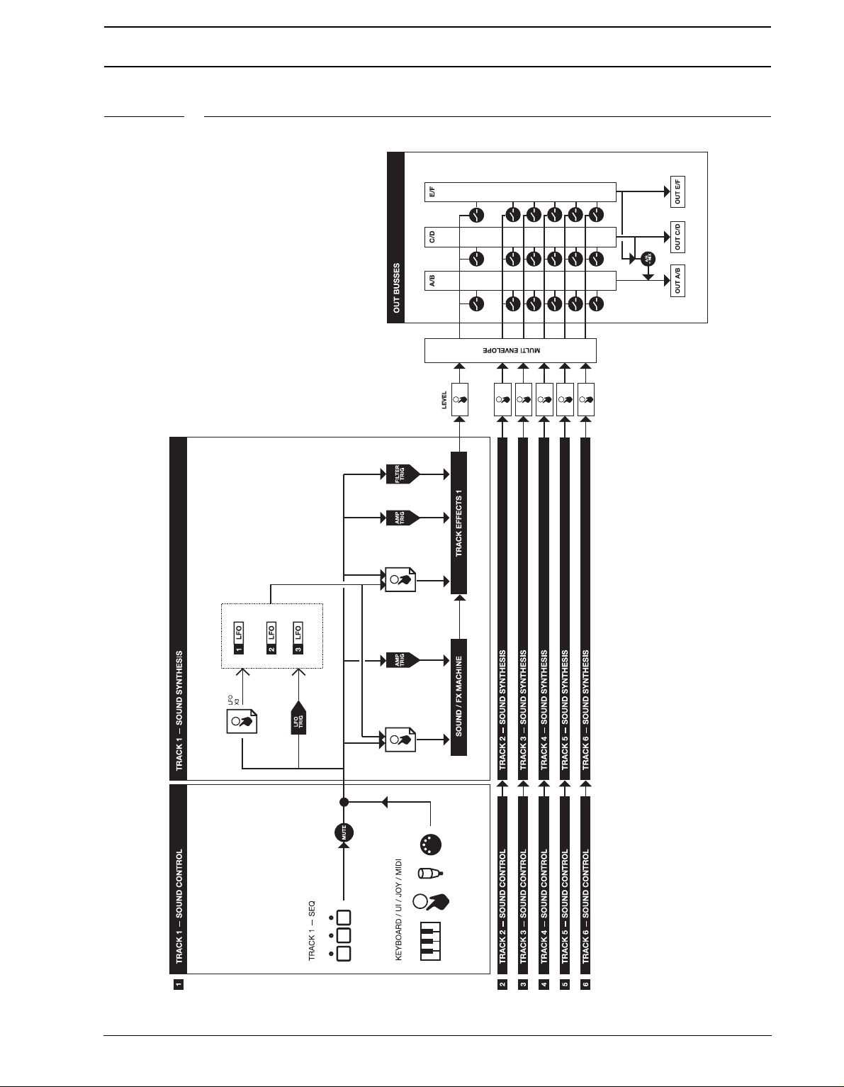
MONOMACHINE OVERVIEW
FIGURE 1. Monomachine sound synthesis overview
15
Page 24

MONOMACHINE SYNTHESIS ARRANGEMENT
MONOMACHINE SYNTHESIS ARRANGEMENT
The basic sound generating unit in the Monomachine is called a machine. Each machine is
designed for generating sounds from a specific technique or method, such as analogue
style pulse, SID MOS 6581 or dynamic FM. The sound generating machines allow you to
get many different starting points with varied sound characteristics.
The machines are grouped in so called Mono-synths. It can be viewed as if the machines in
a Mono-synth belong to the same family. For example, in the FM+ family there are a total of
3 machines for static, parallel and dynamic FM synthesis. Despite the fact that each
machine is based on the family synthesis, each machine can have a unique parameter set.
The parameters are selected individually to give the user the best control of the machines.
There is a special Mono-synth named FX. The machines in this family do not generate
sounds, but offer effects for other tracks.
Description of Mono-synths and their parameters are covered in Appendix A.
Each of the six tracks can have any machine assigned to it. The assignment of machines
and their parameter settings are collected in kits. Editing the kits is discussed in section
“KIT EDITING”, on page 21.
All six tracks have their dedicated effect modules. The track effect system consists of the
parameters found in the AMPLIFICATION, FILTER and EFFECT pages. Each track effect
system delivers hi/lo/band-pass resonant 24-db filter with envelope and individual Q-control, 1-band eq, sample rate reduction, distortion and tempo synchronised tape-style delay.
You will also find controls for left/right-pan and portamento speed among the the track
effects. The track effects are explained in depth in section “TRACK EFFECTS”, on
page 25.
Each track offers three powerful Low Frequency Oscillators (LFO’s). The three LFO’s offer
identical functionality, and can be assigned to any machine, track effect or LFO parameter.
You will find more information about the LFO’s on page 34.
16
Page 25

MONOMACHINE SYNTHESIS ARRANGEMENT
MONOMACHINE KITS
The Monomachine does not arrange sounds in what is commonly referred to as “patches”.
he Monomachine equivalence of a “patch” depends on which way you are using it.
T
• If you use the six tracks as individual synthesizers, or in POLY mode, then you
could see a kit as carrying six “patches”. The kit would then be the equivalence to
what in common synthesizer terms is referred to as a “performance”.
• If you use the MULTI TRIG mode, then all six tracks would be trigged from the
Multi Trig track. A kit would then be the direct equivalence of what is commonly
referred to as a “patch”.
• If you use the MULTI TRIG mode and incorporate the sequencer, then your “patch”
ould incorporate both the kit and the sequencer pattern from which it is linked.
w
If you are used to the structure of ordinary synthesizers, the Monomachine way of structuring sounds in patterns and kit might be confusing at first. Hopefully, after some time of use
you will appreciate the flexibility and ease of use of the Monomachine implementation.
THE LINK BETWEEN KITS AND PATTERNS
Each pattern with data is associated with a certain kit, which will be recalled when the pattern is played. This way, you know playing a certain pattern always gives the same result,
and that the parameter locks make sense.
• Be careful to save any changes you have made to your kit that you want to keep.
Changing pattern might change kit and then you will lose the old kit settings.
• If two patterns use the same kit, the kit will not be reloaded when changing pat-
tern.
As a reference, Monomachine kits hold the information specified below:
• The machines selected for each of the 6 tracks
• Parameter settings for the 6 machines
• Parameter settings for the 6 Track Effects
• Parameter settings for the 6x3 LFO’s
• Parameter settings for the 6 MIDI sequencer tracks
• Input and output routings for the 6 tracks.
• Trig track and multi trig settings for the 6 tracks.
• Parameters for the Multi-envelope.
• The kit name
ll kits are battery backed and user definable. A total of 128 user kits can be stored in
A
memory.
17
Page 26
MONOMACHINE SYNTHESIS ARRANGEMENT
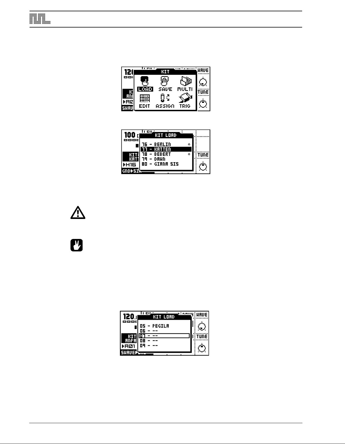
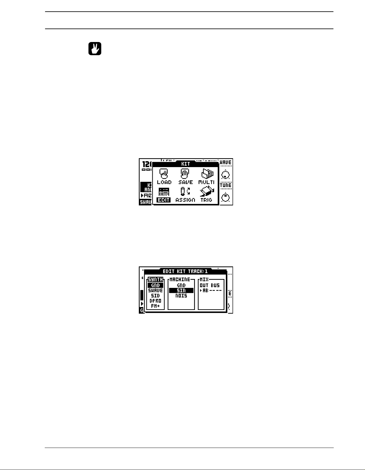
LOADING A KIT
1. Open the KIT window by pressing the [KIT]
[ARROW] keys.
key and select the LOAD icon using the
2. Press [
3. The window presents a list of the kits stored in memory. Use the [UP] and [DOWN] keys
ENTER/YES] to open the LOAD KIT window.
to choose among the 128 kit slots. Press [ENTER/YES] to load the kit of your choice. If
you want to exit without loading a kit, press [EXIT/NO].
• Kits that are not associated with any pattern are distinguished by a little star after
the kit name.
• The kit currently loaded is indicated by an inverted selection box. The focus, when
moved away from the kit currently loaded, is a hollow square box.
LOADING AN EMPTY KIT
To get a clean kit, open the KIT LOAD window as described above and load a position
where no kit was previously saved. The empty positions are indicated with “--” as the kits in
the figure below.
18
After loading an empty kit, you will get six tracks loaded with the GND>SIN machine, and
all track effects and other parameters reset to default values.
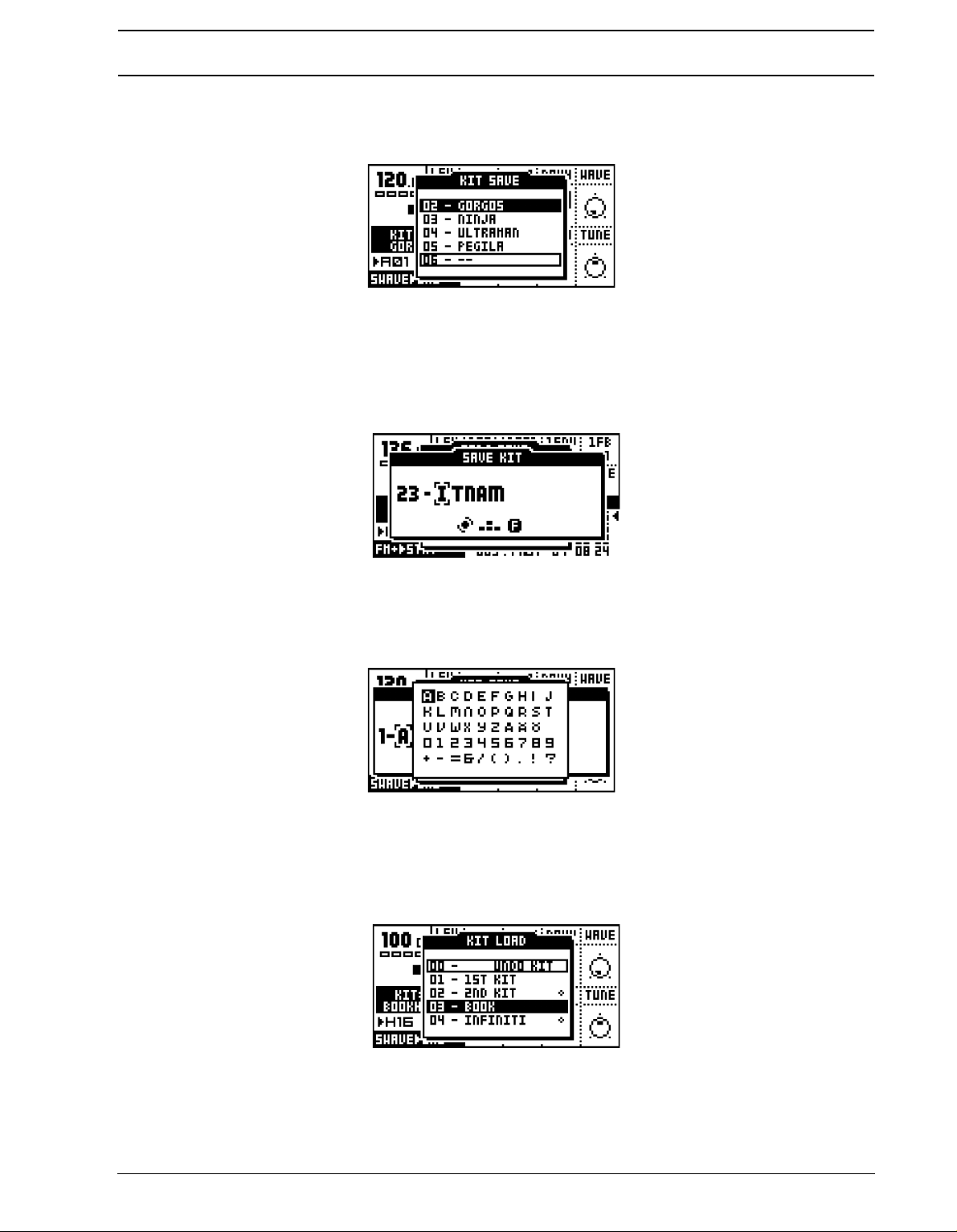
SAVING AND NAMING A KIT
1. Open the KIT window.
Page 27
MONOMACHINE SYNTHESIS ARRANGEMENT
2. Use the arrow keys to move to the “SAVE” icon. Press [
ENTER/YES] to open the KIT
SAVE menu.
3. The screen presents a list of the kits stored in memory. Use the [
UP] and [DOWN] keys
to choose from the 128 kit slots. Press [ENTER/YES] to select the slot where you want
to save your kit.
4. The next window appearing will allow you to name the kit. Use the LEVEL knob or the
[UP] and [DOWN] keys to cycle through the letters. The [LEFT] and [RIGHT] keys move
the cursor backwards and forwards on the line.
5. Pressing the [FUNCTION] key gives access to the “high score” selection method, in
which you see all characters at the same time. Keep the [FUNCTION] key held while
navigating using the [ARROW] keys. Release the [FUNCTION] key, when you have
located the letter of your choice.
6. When the kit name is complete, press [ENTER/YES]
7. If you want to exit without saving the kit, press [EXIT/NO].
to save it.
UNDO KIT
There is a special kit in the first position of the kit list named the “UNDO KIT”.
When you have made unsaved changes to a kit and a new one is loaded, the unsaved old
kit will be stored in the “UNDO KIT” position. When saving a kit over an occupied position in
the kit list, the overwritten kit will also be saved in the “UNDO KIT”.
19
Page 28
MONOMACHINE SYNTHESIS ARRANGEMENT
You can load the “UNDO KIT” to restore your most recent unintentionally lost kit. This can
be useful when accidentally changing pattern and the kit is changed so that your unsaved
changes are lost. When you have restored your kit using the undo kit, don’t forget to save
it.
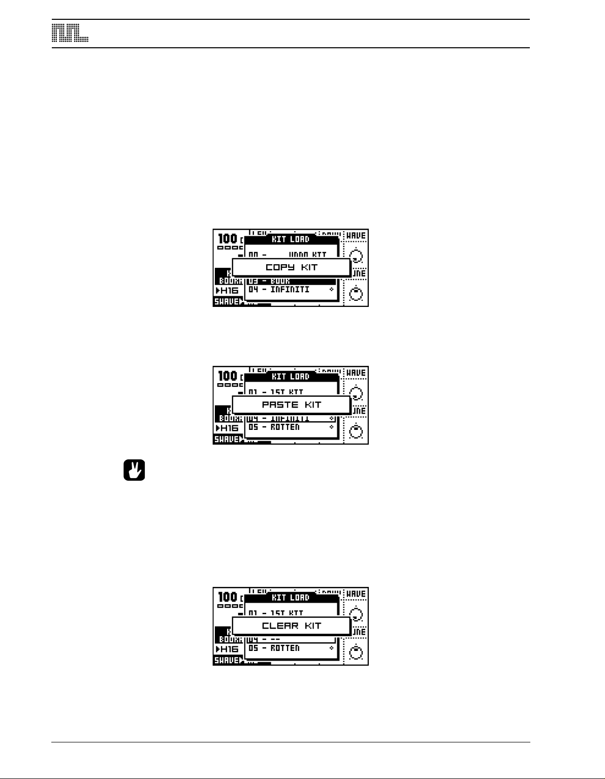
COPY KIT
When in the KIT SAVE or KIT LOAD menus you can copy and paste kits. For loading a kit,
see section “LOADING A KIT”, on page 18. For saving a kit, see section “SAVING AND
NAMING A KIT”, on page 18.
1. When you are in either the KIT SAVE or KIT LOAD menus, select the kit you want to
c
opy, hold down the [FUNCTION] key and press the [RECORD] button. A message say-
ing “COPY KIT” appears.
2. Use the [UP] and [DOWN] keys to scroll to the slot you want to copy the kit to.
3. To paste the kit into the slot, hold [FUNCTION] and press the [STOP] button. The mes-
sage “PASTE KIT” appears.
20
• If you want to undo the action, press the [FUNCTION] + [STOP] buttons again. The
message saying “UNDO KIT” indicates that the paste operation has been undone.
CLEAR KIT
You can also clear kits while in the KIT SAVE or KIT LOAD menus.
1. Select the kit you want to clear, hold down the [FUNCTION] key and press the [PLAY]
button. A message saying “CLEAR KIT” appears.
Page 29
MONOMACHINE SYNTHESIS ARRANGEMENT
• It is also possible to undo this operation. To undo the action, hold the function
[FUNCTION] button and press the [PLAY] button. The message saying “UNDO
KIT” indicates that the clear operation has been undone.
KIT EDITING
You can either create your kit from scratch, or modify an existing one and then save it to a
new position. To load an empty kit, see section “LOADING AN EMPTY KIT”, on page 18.
ASSIGNING A MACHINE TO A TRACK
If you want to create a kit from scratch, follow the instructions below.
1. Open the KIT window and select EDIT KIT using the [ARROW] k
2. Press [ENTER/YES] to enter the EDIT KIT Menu. The EDIT KIT menu is used for
eys].
changing the machine for the active track, and for specifying audio bus routing. For FX
machines you also select the audio input routing for the machine. Read more about FX
machines and routing in section “MONOMACHINE ROUTING”, on page 80.
The <TRACK> LED’s indicate which track you are editing, and it is also displayed in the
name bar at the top of the window. To change the track in focus, use the [TRACK] keys.
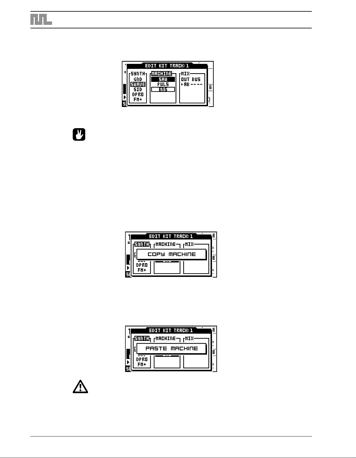
3. Use [LEFT] a
nd [RIGHT] to move between the SYNTH, MACHINE and MIX columns.
[LEFT] and [RIGHT] are also used for moving between the OUT BUS positions. You will
notice that the name of the active column is inverted. You can use the [UP] and [DOWN]
arrows to choose from the available menu choices in the column.
To assing a new machine, first move to the SYNTH column with the [LEFT] and [RIGHT]
keys. Select the Mono-synth of your choice by moving the focus using [UP] and
[DOWN].
21
Page 30
MONOMACHINE SYNTHESIS ARRANGEMENT
Press [RIGHT] once to move the focus to the MACHINE column. Select the machine using
[UP] and [DOWN].
Finally you need to press the [ENTER/YES] key to confirm your selection.
• The Mono-synth and the machine currently assigned to the track are indicated by
inverted selection boxes. The focus, when moved away from the machine currently loaded, is a hollow square box. When [ENTER/YES] is pressed, the current
focus will be assigned, thus changing the square hollow focus to the inverted
box.
COPY MACHINE
You can copy one machine and its settings from one track to another. It is also possible to
copy the current machine and its settings to another kit.
1. In the EDIT KIT menu, press and hold [FUNCTION] and then press [RECORD]. A mes-
sage saying “COPY MACHINE” appears.
2. The settings are placed in the machine copy buffer. Now you can either change track
sing the [TRACK] keys, or load a new kit and select a target track in there.
u
3. Once the target track is selected, press and hold [FUNCTION] and then press [STOP] to
paste the machine settings from the copy buffer. A message saying “PASTE MACHINE”
appears.
22
• Any previous machine settings will be overwritten when pasting.
Page 31

MONOMACHINE SYNTHESIS ARRANGEMENT
• Once the machine is copied into the copy buffer, it can be pasted many times to
several tracks or kits. It will stay in the buffer until it is replaced by a new one.
• See section “SUPER COPY”, on page 53 for a variant of the copy operation.
• The UNDO command is available for this operation. Press the [FUNCTION] +
[STOP] once more to undo the paste operation.
CLEAR MACHINE
It is possible to clear a track, so that it is initialised to the default GND SIN machine.
1. In the EDIT KIT menu, press and hold [
machine. A message saying “CLEAR MACHINE appears.
2. A track that you have used the clear machine function on will be displayed like this:
FUNCTION] and then [PLAY] to clear the
• The clear machine operation can be undone by performing the operation one
more time. A message “UNDO MACHINE” will be shown in the display.
SETTING THE MIX BUS
The Mix bus settings are used for routing the track to the three individual mix busses. It is
also used for routing audio to FX machine effects.
When FX machines are not used on any track, and the master routing is not changed from
the default “3xSTEREO”, the OUT BUS selection in the MIX column select to which pair(s)
of stereo outputs the track will be directed.
For more information on FX machines and how the Mix bus routing can benefit them,
please check section “MONOMACHINE ROUTING”, on page 80.
23
Page 32

MONOMACHINE SYNTHESIS ARRANGEMENT
PARAMETER EDITING
Each Monomachine track offers up to 56 parameters for the sound generation and effects.
hey are divided into seven pages with at most eight parameters in each.
T
The sound generating machines form their sound from one page of up to eight parameters,
called the SYNTHESIS parameters. The track effects are composed from 24 parameters,
divided into three pages of AMPLIFICATION, FILTER and EFFECTS. There are also three
LFO pages, these also bring 24 parameters in total.
First, exit all windows using [EXIT/NO] key. Press the [DATA PAGE] keys until the SYN-
THESIS page is chosen. You should see the base window displayed below. The visual
parameter names and symbols will depend on the machine assigned.
Use the [DATA PAGE] keys to browse through the seven available DATA pages. The
<DATA PAGE> LED’s will indicate the current focus and the visual parameters will be
updated depending on the focus.
Turn the DATA ENTRY knobs. The corresponding visual parameter on the LCD screen
should be updated accordingly. Press and turn the DATA ENTRY knobs for accelerated
editing. Just press it to see the numerical value of the parameter.
• If you want to keep the changes you have done to a kit, don’t forget to save it!
The TUNE parameter is available for all synthesis machines. It allows fine pitch tuning of
100 cents up or down.
For information about the various Mono-synths, and their respective machines, please see
Appendix A. Here you will find background information about all the Mono-synths, and
specifications of the parameters of all machines.
For information about the track effects, please refer to section “TRACK EFFECTS”, on
page 25. For information about the LFO’s, please refer to “LOW FREQUENCY OSCILLATORS” on page 34.
24
Page 33
TRACK EFFECTS
)&"%300.
%*45
&2
'*-5&3
%*45035*0/
".1-*'*$"5*0/
&/7&-01&
4".1-&3"5&
3&%6$5*0/
70-6.&
1"/
%&-":-&7&-
TRACK EFFECTS
The track effects are independent effects systems, available to the six tracks as extensions
to the machine synthesis. This chapter is a reference to all the functions you will find on the
AMPLIFICATION, EFFECT and FILTER pages.
The stereo track effects are applied to the sound signal as described in the figure below:
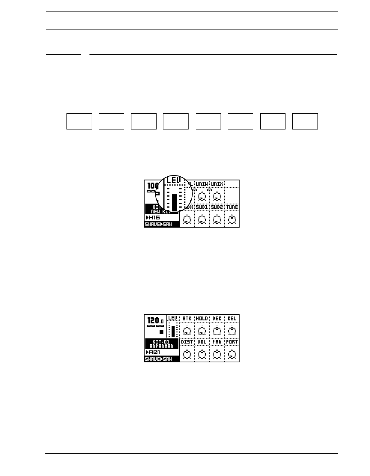
LEVEL
This parameter is available from all DATA pages. You can always reach it with the dedi-
ated LEVEL knob.
c
LEV controls the overall audio level of the track. It is applied at the end of the audio signal
path of the track. The level is designed as a master level control that can not be parameter
locked or assigned as a destination for the LFO’s. If you want to change the volume of a
track, use the track volume parameter on the AMPLIFICATION page. See section “TRACK
VOLUME”, on page 27 for more information on this parameter.
AMPLIFICATION PAGE
In the Amplification page you find the controls for the amplifier envelope (AHDR), distortion,
olume, pan and portamento.
v
AMPLIFIER ENVELOPE
The amplifier envelope is trigged every time an AMP-trig is received. This normally happens when a key has been pressed on the keyboard or if the [TRIG] keys has been
pressed, or if notes have been played from the sequencer or received over MIDI. The
25
Page 34
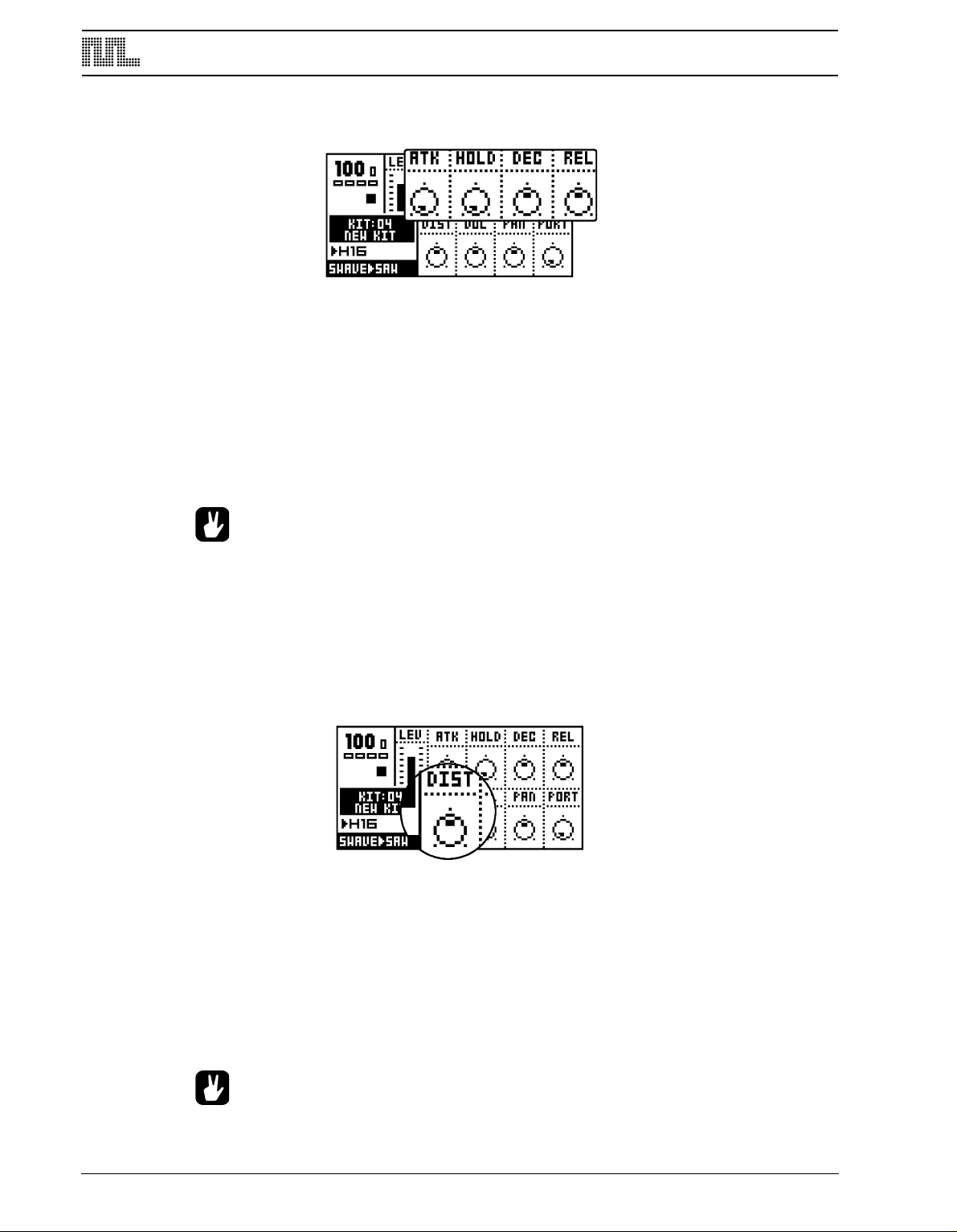
TRACK EFFECTS
AMP-trig can be controlled individually from the sequencer, see section “TRIG TRACKS”,
on page 57 for more information.
ATK (attack). This parameter controls how long time the envelope takes to reach full level.
HOLD (hold) specifies the amount of time the signal is held at full level.
DEC (decay) dictates the amount of time it takes for the audio signal to completely fade out
after the HOLD phase has been passed.
REL (release). If the key played is released at any time (in MIDI this event is named NOTE
OFF), the release phase takes over. The level will then fade by the time specified by the
REL parameter
• The traditional envelope for synthesizers is in the ADSR (attack, decay, sustain,
release) form. For the Monomachine sustain has been exchanged for hold. The
HOLD parameter is very handy when using the sequencer, as it allows you to skip
setting NOTE OFF events in normal use. If you want to simulate ADSR behaviour
you can use the ramp and exp shapes of the LFO’s, with the VOL as destination
parameter.
DISTORTION
Used for adding distortion to a track.
DIST (distortion) controls the signal overload distortion. The distortion is applied as an integrated part of the filter, and controls part of the filter characteristics. It also controls the
headroom for the filter and the EQ.
If the EQ or filter has been used to enhance the signal, the signal might be distorted even
when distortion is set to 0. If you want to remove the overload effect you then need to
increase the headroom by decreasing the distortion parameter below zero. You will hear
the increase in headroom by the signal level decreasing, and the distortion gradually being
removed.
26
• The headroom is not automatically added when the filter Q and EQ are used to
enhance the signal. This is because increasing the headroom means that the
Page 35
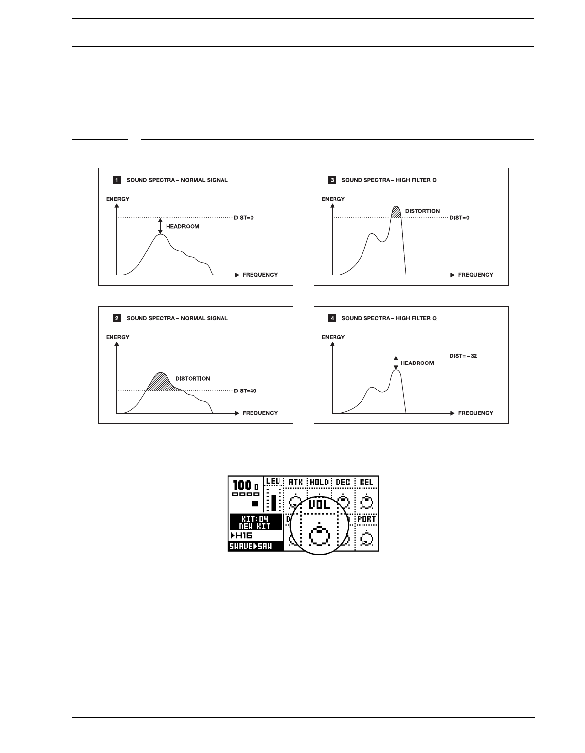
TRACK EFFECTS
audio level decline, and if the audio level would decrease when Q is raised, it
would feel like a loss of bass and a weaker sound. Always leaving full headroom
would result in decreased signal quality, with increased noise. Therefore we allow
you to adjust the distortion to allow for the headroom your sound needs.
FIGURE 2. Simplified visualisation of headroom and distortion
TRACK VOLUME
his volume control is separate from the LEV overall gain control. Track volume can be
T
parameter locked and controlled by the LFO system.
VOL (volume) controls the volume of the track.
27
Page 36
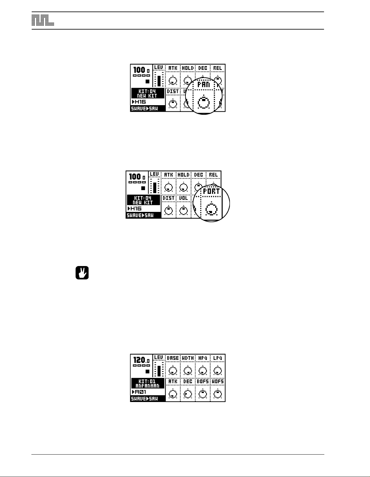
TRACK EFFECTS
PAN
Here the panning for the stereo output is controlled. It operates in stereo when needed
(balance), for example when effecting FX Machines. The default value is center.
PAN (pan) positions the sound in the stereo field. A value of -64 will pan the sound hard
left, a value of + 63 will pan the sound hard right.
PORTAMENTO
Portamento controls the sliding between two consecutive notes played. A slow portamento
speed gives the effect of a slow pitch-glide to the next note.
PORT (portamento) specifies the time it takes for the pitch to slide between any two notes.
See also section “TRIG TRACK SETTINGS”, on page 39 for information on the Trig Portamento setting in the KIT>TRIG menu.
• Use the parameter lock feature in the sequencer to control the portamento speed
individually for separate notes.
• See also section “TRIG TRACK SETTINGS”, on page 39 for information on the
TRIG PORTAMENTO setting in the TRIG menu.
FILTER PAGE
In the Filter page you find the controls for the combined resonant 24dB low/band/high-pass
filter of the Monomachine, including the filter envelope.
28
Page 37
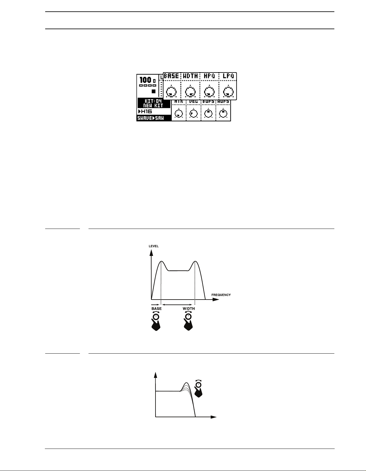
TRACK EFFECTS
FREQUENCY
LPQ
LEVEL
BASIC FILTER CONTROLS
The track effect system offers a resonant 24dB low/high/band-pass filter. The parameters
are untraditional, giving the user control of both the low and high filter cut-offs, as well as a
variable gap band-pass filter.
BASE (filter base) controls the base filter cut-off frequency. When WDTH is set to its maximal value, the BASE parameter functions as the cut off parameter of a high-pass filter.
WDTH (filter width controls the filter gap width, that is the distance between the high pass
and low pass cut-off frequencies. When the BASE is set to its minimum value, the WDTH
parameter functions as the cut off parameter of a low-pass filter.
HPQ (high pass filter Q) controls how much the volume is boosted around the high-pass
cut off frequency.
LPQ (low pass filter Q) controls how much the volume is boosted around the low-pass cut
off frequency.
FIGURE 3. How the BASE and WDTH parameters works.
FIGURE 4. How LPQ affecs the audio signal.
29
Page 38
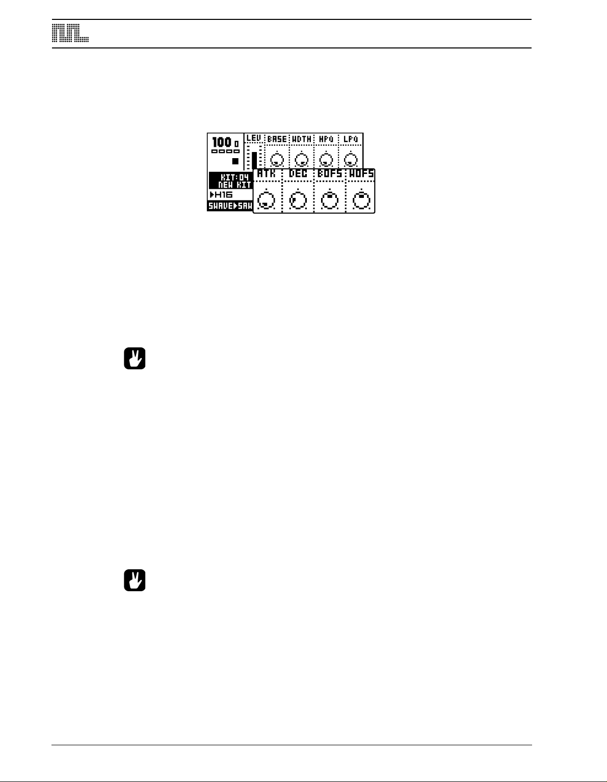
TRACK EFFECTS
FILTER ENVELOPE
The filter envelope is trigged every time a FILTER-trig is received. This normally happens
when a key on the keyboard or one of the [TRIG] keys has been pressed, or played from
the sequencer or received over MIDI. The FILTER-trig can be controlled individually from
the sequencer, see section “TRIG TRACKS”, on page 57 for more information.
ATK (filter envelope attack) controls the attack of the filter envelope
DEC (filter envelope decay) controls the decay of the filter envelope
BOFS (filter base envelope offset) sets the value that will be added to the filter BASE
parameter. BOFS is controlled by ATK and DEC.
WOFS (filter width envelope offset) sets the value that will be added to the filter WDTH
parameter. WOFS is controlled by ATK and DEC.
• To make a familiar “synth-bass” low pass filter bump each time the note is trigged,
set the WDTH to around 64, and turn up the WOFS to around 32. Then turn the
LPQ up until you get the amount of Low Pass filter Q you prefer.
FILTER TRACKING
The filter normally tracks the pitch of the note played. The high pass filter starts cutting two
octaves under the base pitch when the BASE parameter is set to zero.
Both the BASE and the WDTH parameters rise one octave for eight steps. This exact locking of the filter to octaves is useful if you want to use high filter Q settings to be used for
pitch.
The filter tracking can be bypassed for the high pass and the low pass filter individually. You
find the controls for doing this under the KEY tab in the KIT>ASSIGN window, see section
“KEY TRACKING”, on page 39 for more information.
• If you want to use the high pass filter Q as low frequency “loudness” boost, it is
good to turn off the filter tracking parameter HPF.
30
Page 39

TRACK EFFECTS
EFFECTS PAGE
In the EFFECTS page you find the controls for the 1-band EQ, sample rate reduction, and
he tempo-synchronised tape-style delay.
t
EQ
Using the 1-band parametric EQ, you can boost or reduce a certain frequency band.
EQF (EQ frequency) sets the frequency that will be affected by the EQG parameter.
EQG (EQ gain) parameter controls how much the EQ will boost (gain) or reduce the signal
around the EQF frequency. Positive values boost, and negative reduce the signal up to a
maximum of 36dB.
• If you notice signal overload when you boost the signal you might need to
increase your headroom by decreasing the DIST parameter on the Amplification
page. Please see section “DISTORTION”, on page 26 for more information.
SAMPLE RATE REDUCTION
The sample rate reduction effect resamples the signal at a lower sample rate, introducing
aliasing effects which gives a digital “lo-fi” effect.
SRR (sample rate reduction) controls the amount of sample rate reduction down to a lowest of 2.8kHz.
• The sample rate reduction often gives best effect on signals with some, but not
too much, high frequency contents. Sound with too much high frequency information might introduce too much aliasing, resulting in a very disharmonic signal.
31
Page 40
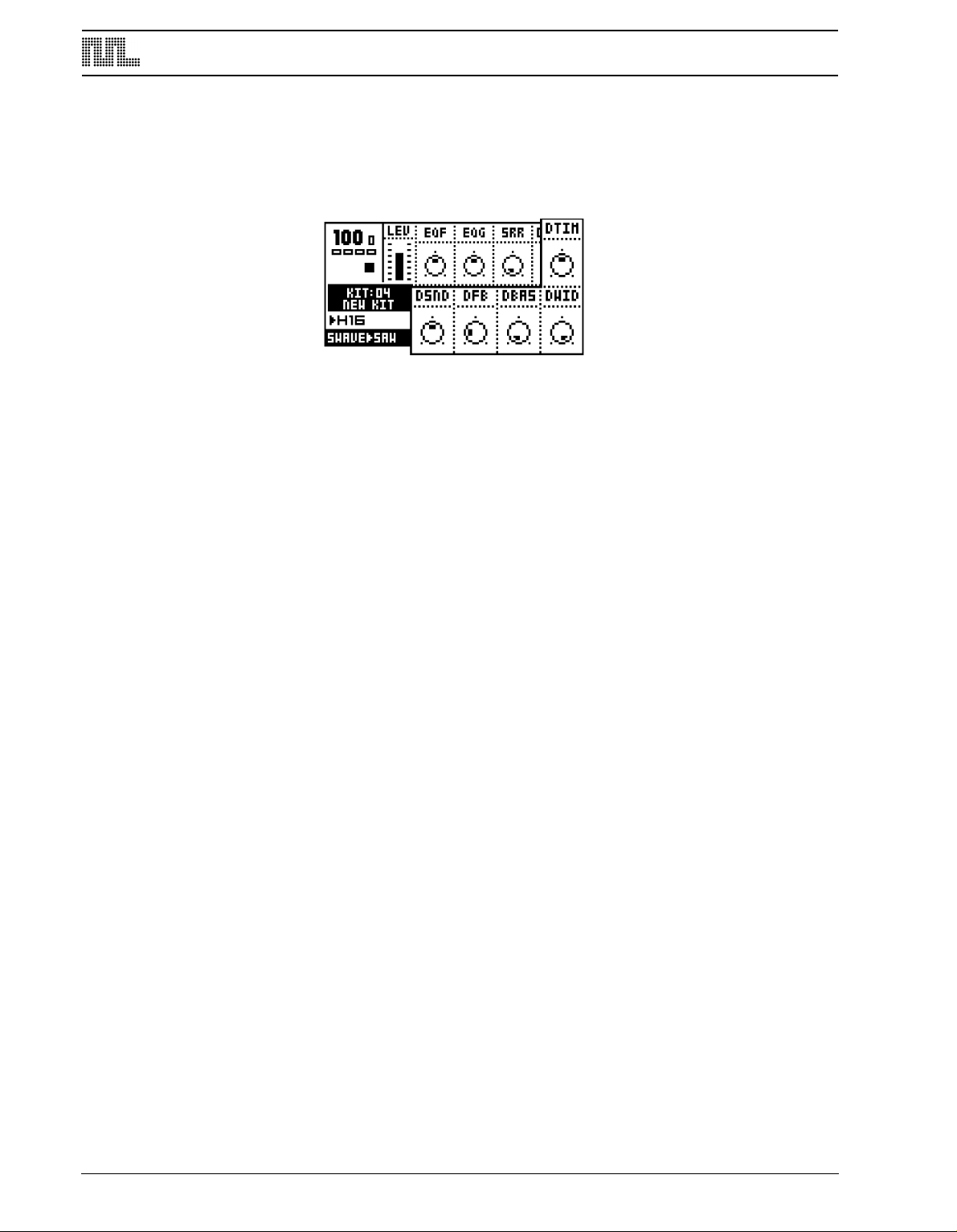
TRACK EFFECTS
DELAY
The delay of the Monomachine is a single tap delay with real-time adjustable delay time.
Some of its functionality can resemble tape loops and solid state CCD delays. The delay
time is always synchronised to the global tempo setting.
DSND (delay send) controls the level of sound that will be sent to the delay loop. To get any
effect from the delay you first need to adjust DSND to some value other than zero and then
generate some sound.
The parameter can be set to positive or negative values. For negative values the stereo
image of the signal will be preserved and for positive values it will be switched left-right.
The feedback loop will also be switched depending if the DSND is set to positive or negative values. This means that you should set negative DSND values to get delay with preserved stereo image, and positive values for ping-pong delay.
DTIM (delay time) controls the delay time of the delay loop. The actual delay time is relative
to the current tempo, and it is measured in 256th notes. For instance, for a one beat delay
(four 16th notes) delay time should be set to 64.
When changing the DTIM parameter or changing the tempo you will hear the contents in
the delay loop speed up or down to adjust to the new tempo set. This behaviour allows the
delay time parameter to be changed at any time, without the typical digital artefacts or brief
silence sometimes experienced when adjusting delay time of digital delays.
DFB (delay feedback) parameter controls how much of the delay output sound will be fed
back into the input of the delay. Using the delay feedback you can make delays with several or infinite echoes.
DBAS (delay filter base) controls the high pass filtering of the signal from the delay feedback loop.
DWID (delay filter width) controls the low pass filtering of the signal from the delay feedback loop, relative the DBAS parameter.
32
Page 41
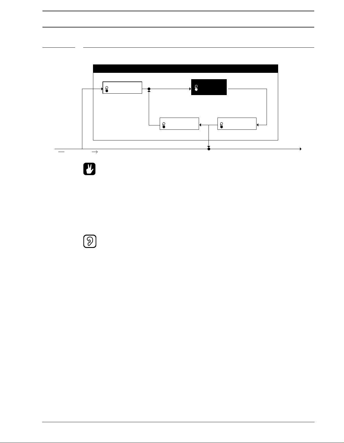
TRACK EFFECTS
DELAY FILTER:
DBAS=FILTER BASE
DWID=FILTER WIDTH
DELAY FEEDBACK:
DFB=DELAY FEEDBACK
%&-":-001
%5*.%&-":5*.&
5"1&41&&%
DELAY SEND LEVEL:
DSND=DELAY SEND
53"$,&''&$5%&-":
"6%*04*(/"-1"5)
FIGURE 5. The function of the delay
• For using the delay for delay-line style sound sculpturing, try setting DTIM very
low together with a DFB value above 32. Then play around with the delay filter settings.
• Try applying an LFO to DTIM for interesting speed-modulating effects!
• Using the DBAS and DWID parameters you can make the delay “echoes” sound
sequentially different as the sound goes round the delay loop. Good for dubinspired delays.
• Watch your tweeters and ears! Feedback values below 64 will cause the sound in
the delay loop to diminish over time, but values above 64 will cause the sound to
grow until maximum audio level is reached and then distort!
33
Page 42

LOW FREQUENCY OSCILLATORS
LOW FREQUENCY OSCILLATORS
Each of the 6 tracks in the Monomachine offers 3 interlaced low frequency oscillators
(LFO’s), which can be used to modulate any track parameter. A typical application of an
LFO is to let it sweep a filter cut-off frequency. The 18 interlaced LFO’s offer 11 waveforms
and 5 trig modes. The LFO’s are tied to their specific tracks, and are shared between the
internal sequencer and the midi sequencer. The speed of the LFO’s is synchronised to the
global tempo.
First select a track using the [TRACK] keys that you want to alter the LFO’s for. Then use
the [DATA PAGE] keys to locate one of the three LFO pages. All the three LFO’s of the
track are identical. The <DATA ENTRY> LED’s indicate which DATA page is currently
selected, and the DATA ENTRY knobs control the parameters of the DATA page selected.
LFO CONTROLS
The three LFO’s of each track are identical. They can control any parameter of the track for
the internal or the MIDI sequencer, as well as the other LFO’s. The LFO control interface is
printed below:
PAGE (page) selects which DATA page the LFO targets.
DEST (destination) chooses the parameter from the DATA page chosen by the PAGE that
is modulated. All seven DATA pages, plus the MIDI sequencer are accessible by the LFO’s.
There’s also a special pitch page, PTCH. If the DEST is PTCH 8 destinations are available,
offering various ranges to allow for both subtle vibrato and full range frequency sweeps.
TRIG (trig mode) is an important parameter for getting the most out of the LFO's. The trig
modes are described in the list below, and their function is visualised in combination with
the waveforms in Figure 3 on page 32.
• FREE = T
he LFO is running continuously, never restarting or stopping.
• TRIG = The waveform is restarted for each LFO-trig, and then runs continuously.
• HOLD = The waveform is running free in the background, but the output LFO level is
latched for each LFO-trig and held still until the next LFO-trig.
• ONE = The waveform is restarted for each LFO-trig, then runs for one cycle and finally
stops and holds the last LFO level.
• HALF = The waveform is restarted for each LFO-trig, then runs for one half cycle and
finally stops and holds the last LFO level.
WAVE (waveform) selects the waveform for the LFO from the eleven shapes available.
There are 5 basic shapes plus mirrored copies of all but the RND random (“RND”) shape.
Select the appropriate waveform with the WAVE knob.
34
MULT (multplier) multplies the SPD parameter by the set amount of times.
Page 43

LOW FREQUENCY OSCILLATORS
&91
J&91
SPD (speed) is a linear controller that sets a base speed that is multiplied with the MULT
parameter, always in relation to the master tempo. The use of both a speed controller and a
multiplier allows a very wide range of speeds, but still provides a high degree of control. To
get the finest resolution keep the MULT parameter set as low as possible.
Increasing SPD values gives shorter LFO cycle times. Each increase of the Multiplier
halves the LFO cycle time. For LFO speed synchronised to straight beats, try setting SPD
to 16, 32, 64 or 127. For example setting the MULT to 2x and SPD to 64 gives a cycle time
of sixteen 16th notes (one full page).
INTL (interlace) is a function taken straight from the Sidstation. Interlace is the process of
alternating the LFO waveform with zero. The speed of the zero-alternating cycles is controlled by the INTL parameter. The interlace is switched off when set to zero.
DPTH (depth) is the amount of the LFO output level that is applied to the target parameter.
Setting DPTH to 127 allows for modulating a parameter to and from any extreme value. For
example, if the target parameter is set to 64 a DPTH setting of 64 is sufficient for modulating the target value to its minimum (0) and maximum (127).
FIGURE 6. Monomachine LFO waveform and trig modes
35
Page 44

LOW FREQUENCY OSCILLATORS
• If you select the same destination for two different LFO tracks their outputs will be
added, making advanced layered LFO’s possible.
• You can create complex modulations by letting an LFO control a parameter of
another one.
• In the Monomachine you can sequence LFO-trig separately from other trigs.
Check page 57 for more information on the trig tracks.
• Interlace can be particularly interesting to use with trigged ramps with pitch as
estination for creating glittery rain-style effects.
d
• For arcade game sounds, use a saw LFO with a DPTH of 127, a MULT of 64x and
modulate PTCH set to 16OCT.
36
Page 45

ADDITIONAL KIT SETTINGS
ADDITIONAL KIT SETTINGS
This chapter deals with all kit settings not covered in the previous chapters.
ASSIGN
This menu allows the joystick, note velocity and note position tracking to be assigned to up
to two parameters of choice. This can allow for a lot of dynamic depth of the sound with little effort.
1. Press the [
2. Press [ENTER/YES] to enter the ASSIGN menu. In the ASSIGN window you will find a
minimum of four and a maximum of six tabs. Navigate between the tabs using the
[LEFT] and [RIGHT] keys. Use the DATA ENTRY knobs to change settings of the
parameters found in the tabs. The settings made here are applied per track. Select
which track you want to edit the assign for with the [TRACK] keys.
All tabs have two rows with three parameters in each in common.
PAGE (page) selects between the seven DATA pages, plus the special pitch destination,
just as on the LFO’s.
KIT] key and navigate to the ASSIGN icon using the [ARROW] keys.
DEST (destination) parameter allows to select one of the eight parameters in the DATA
page chosen by the PAGE parameter.
ADD (add/depth) controls how much of the chosen parameter that will affect the destina-
tion. ADD can be set to positive and negative amounts.
• Setting ADD to +63 or -64 allows for modulating a parameter to any extreme value.
For example, if the target parameter is set to 64 an ADD setting of +32 is sufficient
for modulating the target value to its maximum (127). If the target value is set to
zero, an ADD setting of +64 is needed for the target to be able to reach its maximum value.
37
Page 46

ADDITIONAL KIT SETTINGS
• The copy, clear, paste and undo commands are available in the ASSIGN menu.
ress [FUNCTION] + [REC], [PLAY] and [STOP] to conduct these operations. All
P
tabs are copied as a whole, for easy transformation to other tracks or kits.
JOYSTICK
The first two to four tabs contain the parameters for the joystick.
The first tab can control the right or the left, or both right and left directions of the joystick,
depending of the value of the
MIRR (mirror) dictates how the joystick should react. If MIRR is set to OFF, the right and left
directions of the joystick have individual parameter pages named “JOY R” and “JOY L”. If
MIRR is set to ON, the right and left directions get the same settings. The parameters of
the “JOY RL” page are applied to the right direction, and inverted for the left.
The “JOY U/D” tab has the same function as the “JOY R/L” just described, but controls the
assign for the up and down directions of the joystick.
• Information for the SFX-60MKII, and for controlling the SFX-6 externally:
The Joystick is mapped to Pitch bend for left and right directions, Modulation
Wheel (CTRL CHANGE 1) for upward direction and Breath controller (CTRL
CHANGE 2) for downward direction.
VELOCITY
Key velocity is the name for how hard the key is played on the keyboard, or more correctly,
the amount of time it takes from the key is pressed until it reaches the base. No parameters
additional to the DEST and ADD are found here.
• The key velocity control is mainly for live keyboard playing or sequencing with an
external sequencer. The internal sequencer always plays notes with velocity set to
100. Volume and other parameters are instead usually controlled with the parameter locks.
38
Page 47

ADDITIONAL KIT SETTINGS
KEY TRACKING
The Key Tracking is connected to the note index from the last key pressed. For example, if
C-1 was pressed, the key tracking value will be low, and if C-8 was pressed it would reach
almost its maximum value.
There are two additional parameters on the Key Tracking controlling if the high pass and/or
low pass filter should automatically track the pitch. See page 29 for more information on the
filter.
HPF (High pass filter tracking) disconnects the standard filter tracking of the high pass filter
if set to OFF.
LPF (Low pass filter tracking) disconnects the standard filter tracking of the low pass filter if
set to OFF.
TRIG TRACK SETTINGS
The trig track settings is a group of parameters which affect the way certain aspects of the
s
ound in the track are trigged.
1. You find the TRIG window in the KIT menu. Press the [KIT] key and navigate to the
TRIG icon using the [ARROW] keys.
2. Press [
will find five parameters. Navigate between the parameters using the [UP] and [DOWN]
keys. Use the [LEFT] and [RIGHT] keys to adjust the parameter values.
ENTER/YES] to enter the TRIG TRACK menu. In the TRIG TRACK window you
TRIG POS (trig position) allows you to forward the notes being played on the current track
to another. For example, if you edit TRIG POS for track 1, and set it to point to track 3, then
track 3 will also play notes that are sent to track 1. You can chain TRIG POS, so that several tracks can be trigged from one.
39
Page 48

ADDITIONAL KIT SETTINGS
PORTAMENTO (portamento has two options. ALWAYS means the portamento will always
be active, gliding between all notes played. ONLY LEGATO makes the portamento active
only when playing overlapped so called legato notes.
LEGATO TRIG MODES The three parameters at the bottom of the window control which of
the AMP, FILTER and LFO trigs will be active for notes played legato.
• For a staccato bass sound it is useful for all trigs to be activated, so the sound will
sound the same, even if two notes are played overlapped by mistake. But for a
lead sound it might be better to not initiate any trigs for notes played legato.
MULTI TRIG
The Multi Trig is a link between the synthesis and the sequencer of the Monomachine.
Using the keyboard MULTI TRIG mode on the SFX-6, or the Multi Trig MIDI channel (see
"MULTI TRIG" on page 89 for more information) you can make advanced monophonic
arrangements. All tracks can unite their efforts in creating one dynamic sound, and the
sequencer can be part of the arrangement.
1. Press the [KIT] key and navigate to the MULTI trig icon using the [ARROW] keys.
2. Press [ENTER/YES] to enter the MULTI TRIG window. Navigate between the available
selections using the [UP] and [DOWN] keys.
In the MULTI TRIG window you will find one main tab named “MULTI MODE” with four
options. To the right there is room for an additional context tab with extra settings for some
selections of the first tab. Navigate between the tabs, and inside the context tab (when
available) using the [LEFT] and [RIGHT] keys. Use the [UP] and [DOWN] keys to adjust
the parameter values. Selections in the MULTI MODE tab need to be confirmed with the
[ENTER/YES] key, whereas the selections in the context tab are effecting immediately.
40
Page 49
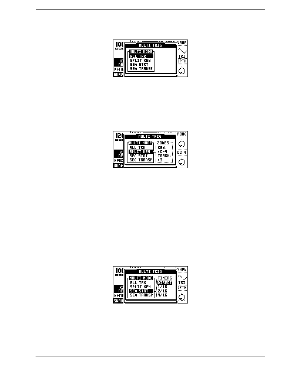
ADDITIONAL KIT SETTINGS
ALL TRK (all track) makes the multi trig channel control all six tracks at once.
Note events received on the multi trig channel will be distributed to all six tracks for parallel
mono operation. The joystick controllers, velocity and key tracking will control all tracks
simultaneously, as assigned in the Assign window (see page 37). The Multi Env is applied
to the All Track MULTI TRIG mode (see page 42). There is no context tab for the All Track
selection.
SPLIT KEY (split mode) allows you to split the keyboard in two zones, each controlling part
of the tracks.
There is an additional tab for the split mode, called ZONES. From the ZONES tab you control which tracks will be devoted to the upper and the lower part of the keyboard, and where
the split point is located on the keyboard.
The TRACK parameter controls which will be the first track to be controlled by the upper
part of the keyboard. All tracks above this one will be controlled by the upper part and the
rest by the lower.
The KEY parameter controls which key is the first to control the upper part of the tracks. All
keys from this one will be directed to control the upper section of the tracks.
For example the settings KEY: C-4 and TRACK: 3 plays tracks 3 to 6 from C-4 and up and
tracks 1 to 2 below C-4.
SEQ START (sequencer start) makes the sequence restart for each note played. The
sequence will be transposed based on which note is played. The original pitch will be
invoked on C-4. The multi envelope is trigged when notes are played (see page 42).
41
Page 50
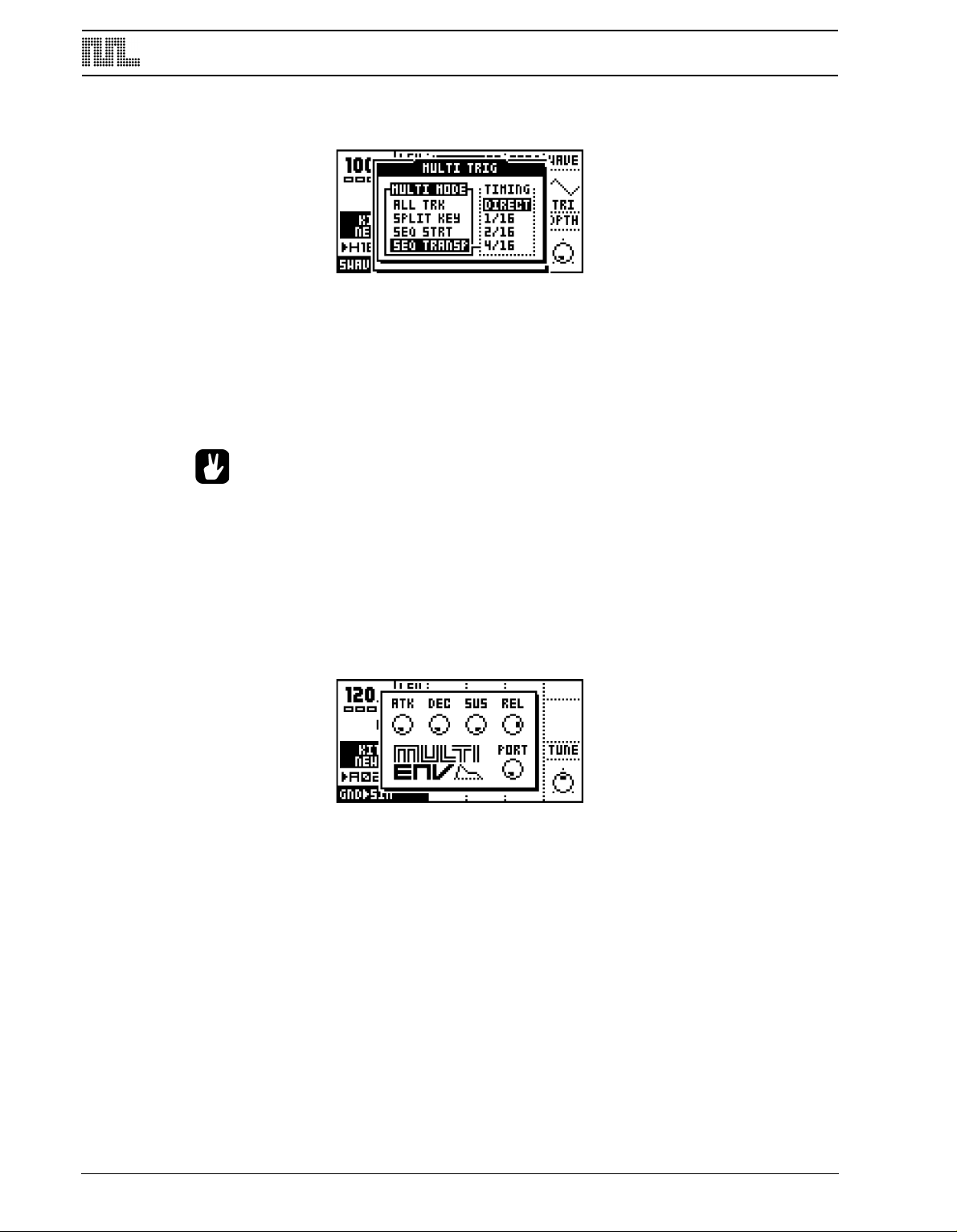
ADDITIONAL KIT SETTINGS
SEQ TRNSP (sequencer transpose) makes a sequence start and transposes the
sequence for the first note received on the multi trig channel.
Subsequent notes will only transpose the sequence and trig the multi envelope, so that the
sequence loop is never broken.
The action of the SEQ START and SEQ TRNSP modes can be delayed to an even bar of
the loop. This is controlled by the context menu named TIMING. If you want to stay in the
beat, set the TIMING parameter to what you prefer. A setting of 16/16 delays the action
until a full page of 16 trigs is played (four beats) in normal tempo mode.
• All arpeggiators of the tracks retain their function in the All Track MULTI TRIG
mode. Interesting results can be yield with different arpeggiator settings and
speeds for the tracks that then are activated in parallel from the Multi Trig channel.
MULTI ENV
The multi envelope is an additional envelope applied to all the tracks in the MULTI TRIG
modes excluding the SPLIT mode. You reach it by pressing both the [DATA PAGE] keys
simultaneously.
The multi envelope is a standard ADSR envelope that is applied on top of the track envelopes, allowing all the tracks to be treated as one massive monophonic track. Note that you
will only hear the effects of the multi envelope when sound are played from the multi trig
channel, and not from the SPLIT mode.
ATK (attack) dictates the amount of time it take for the audio to rise to full volume after
pressing a key.
DEC (decay) sets the time it takes for the sound, after the attack phase, to reach the sustain level.
SUS (sustain) is the signal level during the time a key is being held.
42
REL (release) sets the time it takes for the signal to decay to zero, once the key has been
released.(127 means infinite time to decay)
Page 51

ADDITIONAL KIT SETTINGS
PORT (portamento) sets the amount time it will take the for pitch of the sequence to slide
between two different notes.
• Sound played on the individual tracks while the multi trig is active will be under
the influence of the multi envelope, so the sound level might be lower than usual.
• If you prefer to let the effect of the Multi Env be inaudible, apply settings of ATK 0,
DEC 127, SUS 127 and REL 127.
43
Page 52
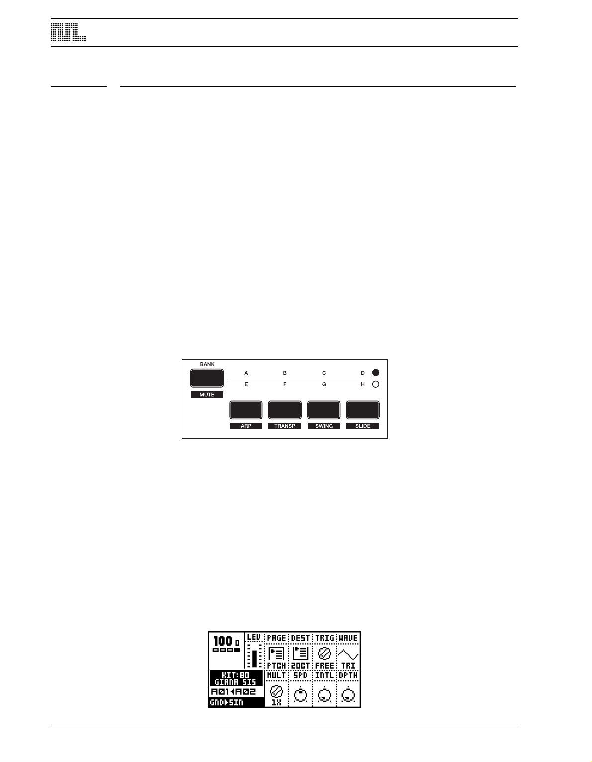
THE PATTERN SEQUENCER
THE PATTERN SEQUENCER
The pattern step sequencer is a central part of the Monomachine sound. It is designed to
be an inspirational tool for pattern based music, or a component in the creation of dynamic
multi-track monophonic sounds.
The sequencer is designed both for live and studio use. The patterns can either be trigged
individually from the user interface or by MIDI commands or they can be linked together
with pattern chaining or in song mode.
BASIC PATTERN OPERATION
The sequencer has several modes of operation, in this chapter we will start by looking at
ow you select and record patterns. Please prepare by following the instructions below.
h
1. First make sure that the <PATTERN> LED is lit and the <SONG> LED is unlit. If neces-
sary toggle it by pressing the [PATTERN/SONG] key.
2. Check that the <MULTI TRIG> LED is unlit so that you are not in MULTI TRIG mode. If
necessary, toggle it by pressing the [MULTI TRIG] key. (SFX-6 only)
3. For external control we recommend using the MIDI auto track channel (see "AUTO
TRACK CH" on page 89). On the SFX-60 MKII you can use an external MIDI keyboard
on this channel when we refer to the keyboard.
44
PATTERN SELECTION
The Monomachine offers 8 banks with 16 patterns in each. The banks are named by the
index A,B,C,D,E,F,G,H. The [BANK GROUP] key selects between pattern bank groups A
to D and E to H. The <BANK GROUP> LED’s indicate the current bank group selection.
1. To select a pattern, press and hold the bank key while pressing a [
TRIG] key. For select-
ing pattern A05, first make sure the bank LED’s indicate that bank group A to D are
selected, then press and hold key [A/E] while pressing the fifth [TRIG] key.
2. While the [BANK] keys are pressed you can tell which patterns are used by the 16
<TRIG> LED’s. LED’s that are red indicate that the corresponding pattern contains data.
If pattern selection is done while the sequencer is playing, the selected pattern will not be
active until the current pattern has played to its end. You will see the index of the pattern to
be played next blinking to the right of the current pattern..
Page 53
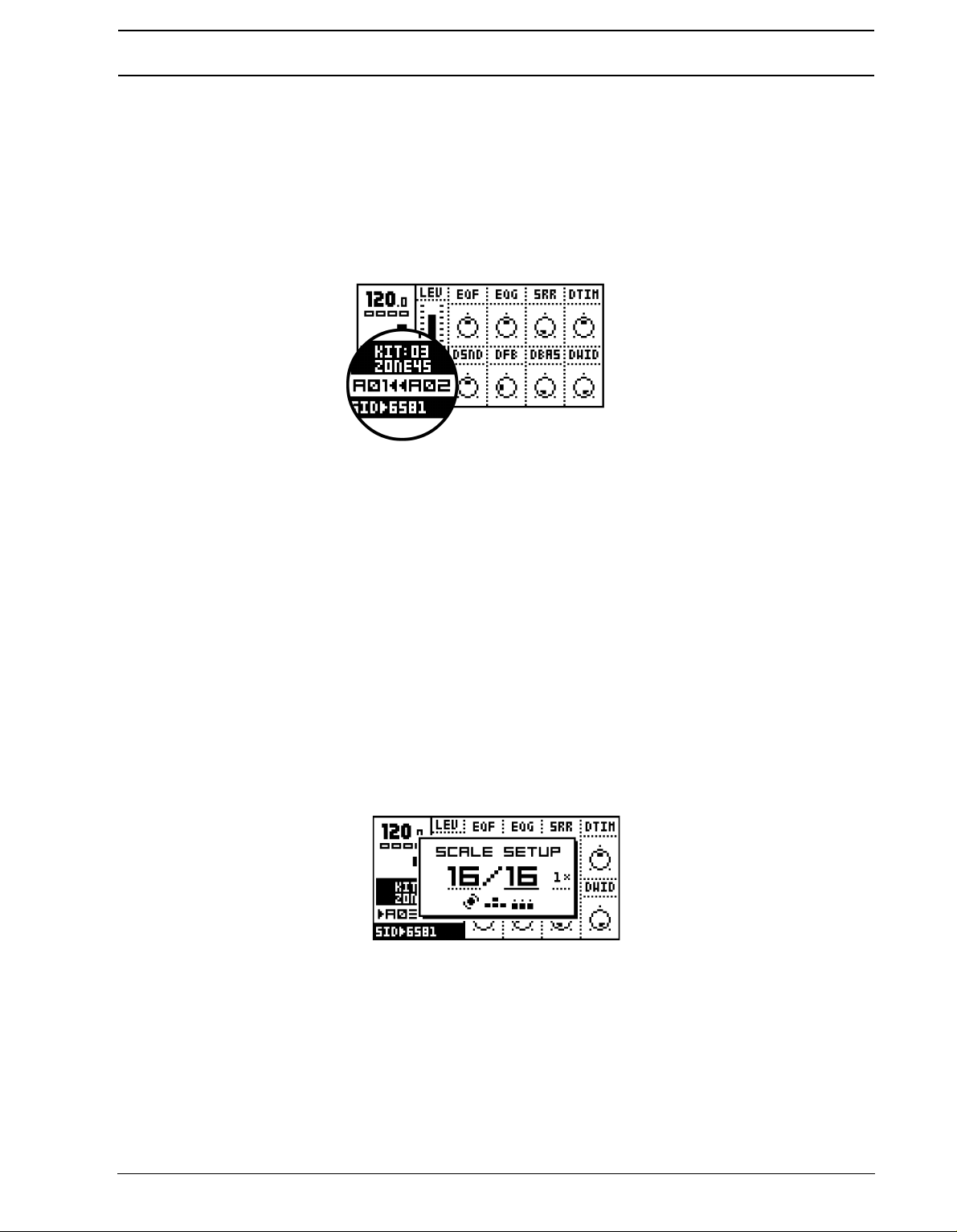
THE PATTERN SEQUENCER
PATTERN CHAINING
You can use pattern chaining to cue up patterns to be played after one another in a loop,
like a simple live sequencer for patterns. In pattern mode, hold a [BANK] button and then
press the [TRIG] key for the pattern you want to be first in the chain. As long as you keep
the first [TRIG] key down, subsequent [TRIG] keys pressed will add patterns to the end of
the chain. It is only possible to chain patterns from one bank, and each pattern may only be
chained once.
Chaining is indicated by a double arrow between the current and the next pattern.
[STOP] will reset the pattern chain to the beginning. Pressing [STOP] twice will exit the
pattern chaining and return to normal operation. Selecting a new pattern exits pattern
chaining as well.
SCALE SETUP
By default the length of a pattern is 4/4 bars, built from 16 steps. We refer to these 16 steps
as one page. A pattern can be extended to up to 64 steps, which uses a maximum of four
pages. All tracks share the same scale length, and are always played in sync.
In GRID RECORDING The [SCALE] key is used to cycle between the active pages, and
the <TRACK PAGE> LED’s indicate which one is currently being edited. When not in GRID
RECORDING mode the LED’s for the available pages for the track are lit with a steady
light. The LED for the page currently playing is flashing.
Press the [SCALE SETUP] key while holding [FUNCTION] to open the SCALE SETUP
window. From here you can set the scale length and playback speed of the pattern currently selected.
There are three parameters available in the SCALE SETUP window. The underlined focus
is moved with the [LEFT] and [RIGHT] keys.
1. The first parameter sets the total number of steps of the pattern. Use [
UP] and [DOWN]
to increase/decrease the number of steps. The LEVEL knob is also controlling this
parameter, and the [TRIG] keys can be used as well to set the end step.
2. The second parameter sets the scale length in divisions of 16 (one full page). If the scale
length is higher than 16 the [SCALE] key need to be used in GRID RECORDING mode
to toggle the focus of the [TRIG] keys between the pages.
45
Page 54

THE PATTERN SEQUENCER
3. The third parameter is the tempo multiplier. There are four possible settings, “1X”, “2X”,
3/4X” and “3/2X”. 2X allows a pattern to be played back at twice the global tempo. 3/4X
“
allows a pattern to be played back at three quarters of the global tempo. 3/2X will play
back a pattern twice as fast as the 3/4X setting. Double speed is useful for increasing the
step resolution to 32th notes. Three quarter-speed is useful when the Monomachine is
playing alongside other instruments set to the same BPM and you want the Monomachine to play triplets.
• Even though you set a pattern to have a certain length using scale setup, you can
change this row by row in the song editor. See section “THE SONG MODE”, on
page 72 for more information.
• The [SCALE] key offers a quick way to cycle the scale length in steps of 16.
• When changing the scale length so more pages come in use, lower pages will
automatically be copied to higher, but only if nothing so far has been programmed
on the pages added. Pages can also be manually copied, see section “TRACK
PAGE COPY”, on page 50.
• The default scale length is 16 which gives the time signature 4/4. Setting the scale
length to 32 gives the double length of the pattern with 4/4 signature.
COMPOSING A PATTERN
This chapter will take you through the details how to create a pattern in GRID RECORDING, LIVE RECORDING and STEP RECORDING mode.
RECORDING PREPARATIONS
Follow the steps below before continuing with any pattern composing.
1. Close all windows that might be open using the [EXIT/NO] key.
2. For SFX-6: Check that the <MULTI TRIG> LED is unlit. Press the [
switch it off if needed.
3. Check that one and only one of the <DATA ENTRY> LED’s are lit. If the four top LED’s
are lit you need to exit the MIDI SEQ mode by pressing [TRIG SELECT] while holding
[FUNCTION].
4. Select a pattern as described in section “PATTERN SELECTION”, on page 44. We rec-
ommend starting with an empty pattern. All patterns in banks E-H are empty as factory
default.
5. Select a kit for the pattern as described in section “LOADING A KIT”, on page 18.
6. Select the track you wish to edit using the [TRACK] keys. Check that the track makes
sound by trigging it using either the Keyboard or the [TRIG] keys.
7. Verify that all the <TRIG TRACK> LED’s are lit. Press the [TRIG SELECT] key to cycle
until all <TRIG TRACK> LED’s are lit if needed.
GRID RECORDING
Grid recording is a method of percussion composing that first was used in vintage drum
machines. In the Monomachine it has been adapted and extended to fit intuitive pattern
based arrangements of melodies and rhythms. In the default GRID RECORDING state, the
16 [TRIG] keys represent 1 page of 16th notes.
MULTI TRIG] key to
46
1. Perform the recording preparations as described in the previous section.
Page 55

THE PATTERN SEQUENCER
2. Enter GRID RECORDING mode by pressing the [
RECORD] key. The <RECORD> LED
above the key should now be firmly lit.
3. You can press [PLAY] if you prefer to listen to the pattern playing while composing. It will
loop over and over, until you press [STOP] to stop the playback or [PLAY] to pause it.
4. Press a [TRIG] key to set a note trig for the corresponding step. The <TRIG> LED’s indi-
cates which steps contain note trigs. You will see that the LED above the [TRIG] key
lights up with a red light as you press it. You can remove a note trig by pressing the corresponding [TRIG] key one more time. The LED should now be switched off.
5. While holding a [
TRIG] key you can see a mini-keyboard appearing after a short delay. It
is located in the lower left corner of the LCD interface. This mini-keyboard indicates the
pitch of the note, both by a marker on the mini-keyboard and the note printed below. The
<KEYBOARD> LED’s of the SFX-6 also indicate the pitch programmed.
6. There are two methods for adjusting the pitch of a trig. You can either press a key on the
keyboard while holding the [TRIG] key to set the pitch indicated by the keyboard key.
You can also use the [ARROW] keys to adjust the pitch programmed while holding the
[TRIG] key. Holding [FUNCTION] while pressing the [RIGHT] or [LEFT] key adjusts the
pitch one full octave up or down.
7. You can set NOTE OFF trigs by pressing the [
TRIG] key while holding [FUNCTION].
NOTE OFF trigs are events that tell that the key is lift up, starting the Release phase of
the Amplitude Envelope (see page 25). NOTE OFF are indicated with yellow <TRIG>
LED’s.
8. Chords can also be programmed. These can be used for POLY mode (see section
“POLY MODE”, on page 68) and trigging the arpeggiator (see section “THE ARPEGGIATOR”, on page 60). If not in POLY mode and if the arpeggiator is not activated, only the
base pitch will sound. You can program chords with the keyboard by pressing more keys
while holding the first base pitch key. The mini-keyboard shows chord-notes as dots. A
scroll list will appear below the mini-keyboard and the base pitch. This list can also be
edited using the [ARROW] keys. Press [ENTER/YES] to enter the list if no chord key is
yet entered.
47
Page 56
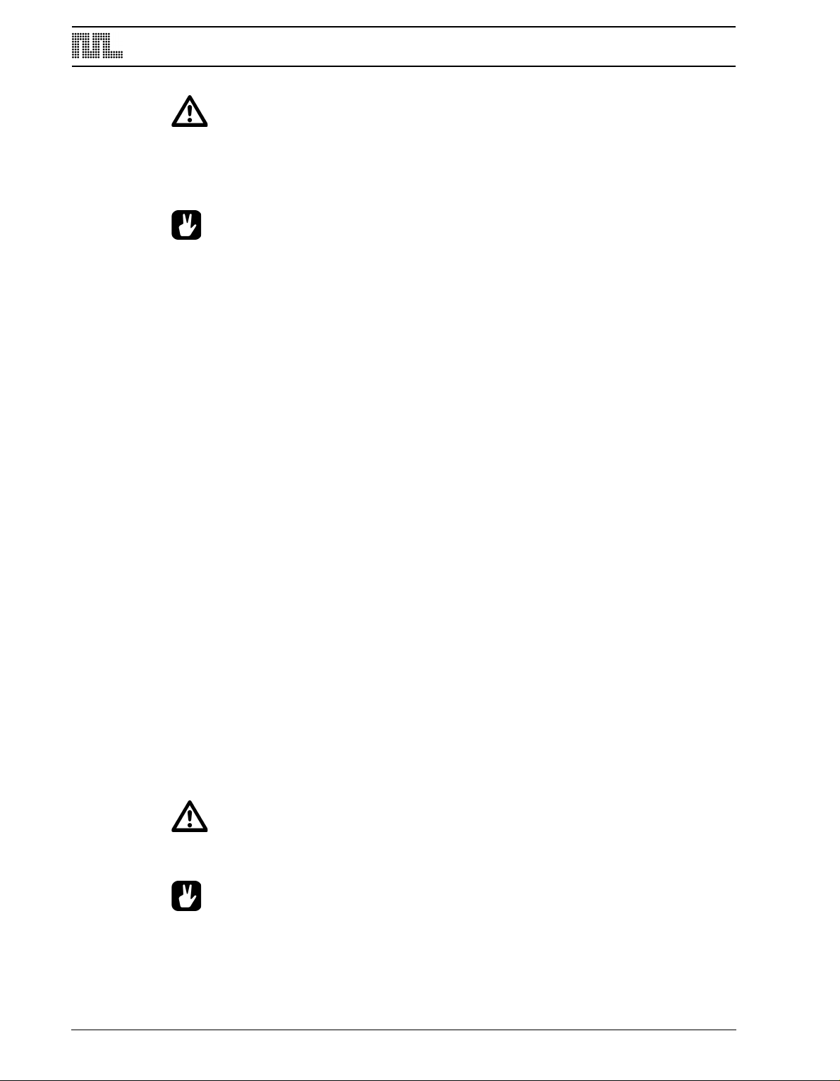
THE PATTERN SEQUENCER
• In the Monomachine, you work directly in the pattern memory. There is no need to
save patterns. If you wish to keep the pattern intact you will have to copy it to
another pattern before you begin editing it. See section “PATTERN COPY”, on
page 52 for more information on copying patterns.
• In GRID RECORDING mode, pressing keys [LEFT] and [RIGHT] while holding
[FUNCTION] rotates the trigs and locks of the track one step.
• You can avoid general need of NOTE OFF trigs by making good use of the HOLD
parameter (see section “AMPLIFIER ENVELOPE”, on page 25).
• Depending on the scale setup, you might have a longer pattern than what is possi-
ble to edit with the 16 LED’s and [TRIG] keys. In that case, you need to use the
[SCALE] key to change between the pages. See section “SCALE SETUP”, on
page 45 for more information.
• The copy, clear, paste and undo functions operate on a specific track when in
GRID RECORDING mode. See section “TRACK COPY” on page 51.
• The copy, clear, paste and undo functions operate on the full pattern when not in
GRID RECORDING mode. See section “PATTERN COPY” on page 52.
LIVE RECORDING
The second method of recording notes in the sequencer is by recording them live while
playing. You can record both from the keyboard and the [TRIG] keys.
1. Begin with following the instruction in section “RECORDING PREPARATIONS”, on
page 46.
2. To start recording in LIVE RECORDING mode, hold [RECORD] while pressing [PLAY].
This starts the sequencer recording and the record LED will start flashing.
3. You can now play notes on the keyboard or the [
and recorded to the closest trig step in the pattern. If a note is played on a step where
there already was a note programmed the new note will replace the old note.
4. Chords can also be recorded in the sequencer. They will only make effect when in POLY
mode (see section “POLY MODE”, on page 68) or when the arpeggiator (see section
“THE ARPEGGIATOR”, on page 60) is active.
5. To erase notes on LIVE RECORDING mode hold [EXIT/NO] when the notes you want to
remove are played.
6. The pattern will loop and be ready for further recording until you press the [STOP] key.
TRIG] keys, and they will be quantised
• All live recorded data will be quantised to the current scale resolution (16th or
32th notes).
48
• If you want to edit the recorded notes, you can use grid recording as described in
section “GRID RECORDING”, on page 46.
Page 57
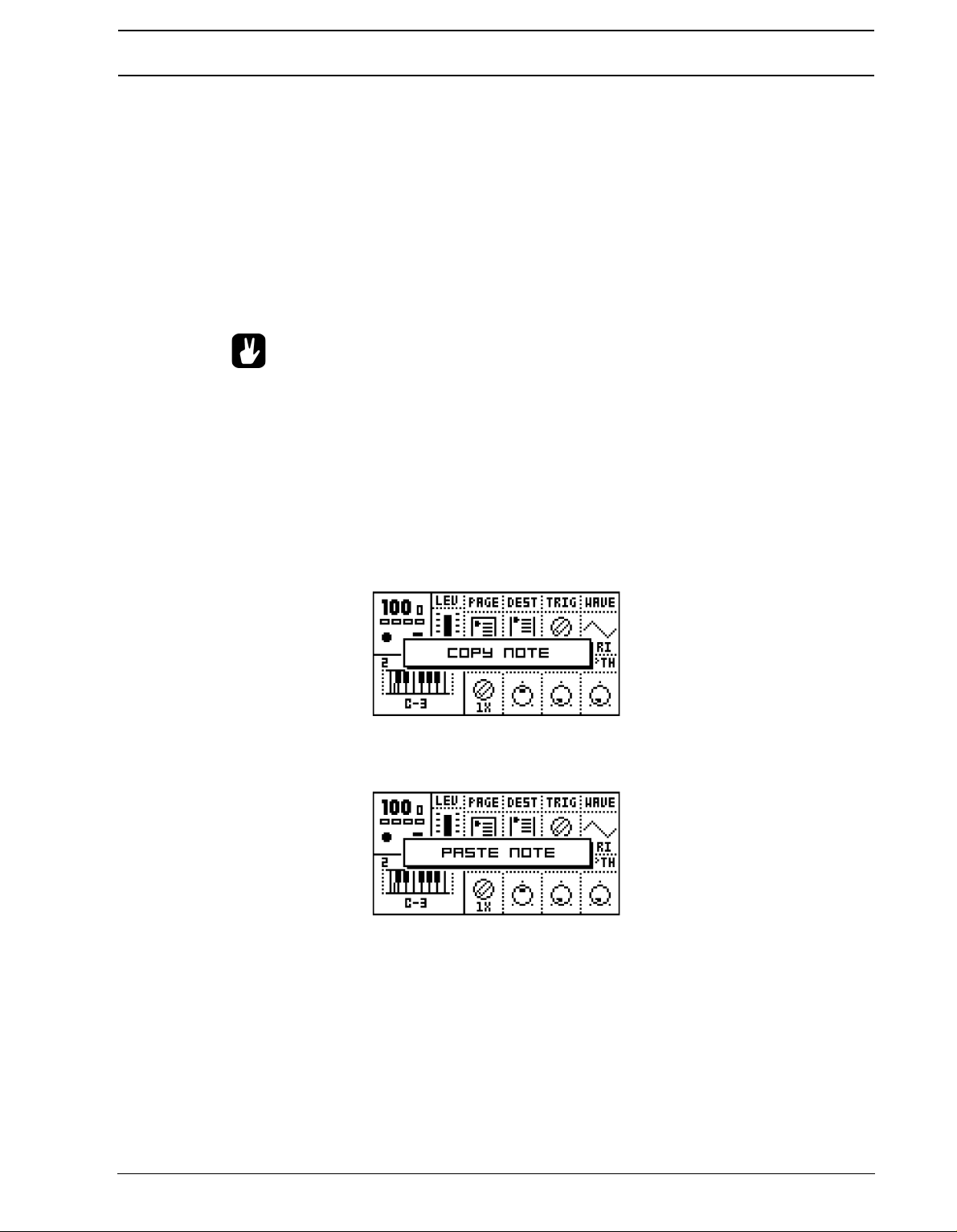
THE PATTERN SEQUENCER
STEP RECORDING
The third method of recording notes differs a bit from the other two methods as data is input
on a step by step basis. You can input notes from the keyboard and the [TRIG] keys
1. Begin with following the instruction in section “RECORDING PREPARATIONS”, on
p
age 46.
2. To enter STEP RECORDING mode, press [REC] and [STOP] at the same time.
3. The pattern will start on the first step of the sequencer. From here the active position will
automatically advance one step forward when a note or chord is programmed.
4. You can use the [LEFT] and [RIGHT] keys to move the editing focus of the pattern.
ress the [EXIT/NO] key to program a NOTE OFF, press [ENTER/YES] to clear a note.
P
• Use the step recording method as an experimental way of creating patterns. Inter-
esting results can be had!
NOTE COPY
It is possible to copy a note trig, complete with all parameter lock settings, and paste it to a
new location in the track.
1. Make sure you are in GRID RECORDING mode, indicated by the <RECORD> LED giv-
ing off a steady light.
2. Press and hold the note trig you want to copy and press the [RECORD] key. A message
“COPY NOTE” will appear.
3. Hold the [TRIG]
key correspondning to the location you want to paste the note to and
press the [STOP] key to complete the paste operation. A message “PASTE NOTE” will
be shown.
CLEAR NOTE PARAMETER LOCKS
Instead of removing the parameter locks from a note you can also use the clear note locks
command.
1. Make sure you are in GRID RECORDING mode. The <RECORD> LED should be lit.
49
Page 58

THE PATTERN SEQUENCER
2. Hold and press the [
TRIG] key you whose content you want to clear. Then press [PLAY]
to clear the note. The message “CLEAR NOTE LOCKS” will appear.
The clear note lock operation can be undone by performing the clear note operation one
more time. The message “UNDO NOTE LOCKS” will be shown in the display.
TRACK PAGE COPY
In GRID RECORDING mode you can copy one page of trig data and paste it to another
page.
1. Make sure you are in GRID RECORDING mode, indicated by the <RECORD> LED giv-
ng off a steady light. Select the source track using the [TRACK] keys.
i
2. Select which page you want to copy by pressing the [SCALE SETUP] key.
3. When you have chosen the page you want to copy, hold the [SCALE SETUP] key and
press [REC]. The message “COPY PAGE” page will appear.
4. Select the pattern page you want to paste the copied page into by pressing the [SCALE
SETUP] key. Paste the data by holding [SCALE SETUP] and then pressing the [STOP]
key. A message saying “PASTE PAGE” will be shown in the display
• Page copy operates on trigs, pitches and parameter locks. Pasting data into a
track overwrites any previous notes, data and parameter locks.
• The track page paste operation can be undone by holding down the [SCALE
SETUP] key while pressing the [STOP] key. A message saying ”UNDO PAGE” will
be shown in the display.
CLEAR TRACK PAGE
It is also possible to clear a track page.
50
Page 59

THE PATTERN SEQUENCER
1. Make sure you are in GRID RECORDING mode.
2. When you are on the track you wish to clear, press and hold [SCALE SETUP].
Then
press [PLAY] to clear the track. The message “CLEAR PAGE” will appear.
• The clear track page operation can be undone by holding the [SCALE KEY] and
pressing the [PLAY] key directly after the clear operation. The message “UNDO
PAGE” will be shown in the display.
TRACK COPY
In GRID RECORDING mode, it is possible to copy the contents of one track to another.
1. Make sure you are in GRID RECORDING mode, indicated by the <RECORD> LED giv-
ing off a steady light. Select the source track pressing the appropriate [TRACK] key.
2. Press [REC] while holding [FUNCTION] to copy the data of the track.The message
“COPY TRACK” will be shown in the display.
3. Select the destination track using the [
4. Paste the data by pressing and holding [FUNCTION] and then pressing the [STOP] key.
TRACK] wheel.
A message saying “PASTE TRACK” will be shown in the display.
• The track data copied consists of notes, parameter locks, the machine selection,
DATA pages and arpeggiator, transpose, swing and slide settings.
• Pasting data into a track overwrites any previous notes, data and parameter locks.
• The paste track operation can be undone by holding down the [FUNCTION] key
while pressing the [STOP] key. A message saying “UNDO TRACK” will be shown
in the display.
51
Page 60

THE PATTERN SEQUENCER
CLEAR TRACK
While in GRID RECORDING mode, it is possible to clear a track.
1. Make sure you are in GRID RECORDING mode. The <RECORD> LED should be lit.
2. When you are on the track you wish to clear, press and hold [FUNCTION].
Then press
[PLAY] to clear the track. The message “CLEAR TRACK” will appear.
• The clear track operation can be undone by performing the clear track operation
one more time. The message “UNDO TRACK” will be shown in the display.
PATTERN COPY
To copy the contents of a pattern to another pattern location, follow the steps below.
1. Make sure that the <RECORD> LED is not lit, so you are not in GRID RECORDING
mode.
2. Select the source pattern by using the [
BANK] and [TRIG] keys. Hold [FUNCTION] and
then press [REC]. A message “COPY PATTERN” will be shown in the display.
3. Choose the pattern where you wish to paste your pattern data.
4. Paste the data by holding [FUNCTION] and then pressing the [STOP] key. A message
“PASTE PATTERN” will be shown in the display.
52
• Pasting data into a pattern overwrites any previous data in the pattern.
• The pattern data that is copied consists of notes, parameter locks, the kit associa-
tion, MIDI sequencer notes and arpeggiato, transpose, swing and slide settings
for all six tracks.
Page 61

THE PATTERN SEQUENCER
• The paste pattern operation can be undone by holding the [FUNCTION] key and
then pressing the [STOP] key. A message saying “UNDO PATTERN” will be shown
in the display.
CLEAR PATTERN
It is also possible to completely clear a pattern of all its content.
1. Make sure you are not in GRID RECORDING mode. The <RECORD> LED should be
ot be lit.
n
2. When you have chosen the pattern you wish to clear, press and hold [FUNCTION] and
then press [PLAY] to clear the pattern. The message “CLEAR PATTERN” will appear
• The clear pattern operation can be undone by performing the clear pattern opera-
tion one more time. The message “UNDO PATTERN” will be shown in the display.
• Pattern clear clears everything, except the kit association.
SUPER COPY
For track, pattern and machine copy operations the default copy behaviour can be replaced
by the super copy function.
1. Hold the [
expand to a larger one including a selection box.
2. You can now release [FUNCTION] while holding [REC]. While still holding [REC], use
the [UP] and [DOWN] keys to manoeuvre the inverted selection box.
3. When [REC] is released the selected copy action will be performed.
4. Paste the data by pressing [FUNCTION] and [STOP]. If you chose to paste a copied
pattern, a window showing “PASTE PATTERN” will appear.
FUNCTION] and [REC] for around a second and the default message-box will
53
Page 62

THE PATTERN SEQUENCER
• Melody copy is a special copy function which copies all pitch data from the track,
but excludes parameter locks and machine selection and settings. Use this to
transport a melody between tracks you are using different machines for.
• The MACHINE selection is a shortcut for copying the machine selection and all
DATA pages, which is normally performed from the EDIT KIT window.
• All super copy functions are delayed until the [REC], [PLAY] or [STOP] key is
released. So even if you get the message “CLEAR PATTERN” it is not performed
until the [REC], [PLAY] or [STOP] key is released, so that you get the chance to
change the default action in the selection box.
• The SUPER COPY screen can only be called when in pattern, grid edit and kit edit
odes.
m
• You can cancel super copy/clear/paste by pressing the [EXIT/NO] key.
• The super paste operation can be undone by performing the super paste opera-
tion one more time. The message “UNDO PATTERN” will be shown in the display
(if a pattern has been copied).
SUPER CLEAR
For track, pattern and machine clear operations the default clear behavior can be replaced
by the super clear function.
1. Hold the [FUNCTION] and [PLAY] for around a second and the default message-box
will expand to a larger one including a selection box.
2. You can now release [
the [UP] and [DOWN] keys to manoeuvre the selection box.
3. When [PLAY] is released the selected clear action will be performed.
FUNCTION] while holding [PLAY]. While still holding [PLAY], use
• The super clear operation can be undone by performing the super clear operation
one more time. An undo message will be shown in the display.
TEMPO
The tempo in the Monomachine is a global parameter. It is however not stored in the global
slots (see page 86). The tempo will control the playback speed of the patterns and also
tempo synchronised parameters in the Monomachine, such as the HOLD parameter, the
delay and LFO speeds and some machine parameters.
54
The tempo is controlled from the TEMPO screen, and can also be set by the song
sequencer.
Page 63

THE PATTERN SEQUENCER
THE TEMPO SCREEN
The tempo screen is opened by pressing the [TEMPO] key.
From here you can use the LEVEL knob to change the current tempo in integer steps. The
[UP] and [DOWN] arrow keys change the decimal part of the tempo. Holding [FUNCTION]
while editing the tempo will delay the change of tempo until you release the [FUNCTION]
key.
• You can temporarily shift the tempo up or down by 10% by pressing the [LEFT] or
[RIGHT] arrow keys. This is very handy when manually syncing your Monomachine to a turntable or a laptop. Note that you do not necessarily need to be in the
TEMPO screen to perform this tempo shift.
TAP TEMPO
To tap a tempo, hold the [FUNCTION] key and tap the [TEMPO] key in a steady rhythm.
After four consecutive taps the average tempo of the taps will be set as the current tempo
and it will be shown in the tap tempo window. You can continue tapping the [TEMPO] key,
and the taps will be used for refine the average tempo. A maximum of 16 tempo taps are
considered.
EXTERNAL SYNCHRONISATION
The Monomachine can be set to either internal or external synchronisation. When in internal clock mode the SFX-6/SFX-60MKII can output a high quality MIDI clock through the
MIDI OUT port. This can be used for keeping external gear in sync with the Monomachine.
When in external MIDI clock synchronisation mode the Monomachine will stay in sync with
an external MIDI clock if present. When in external clock mode the tempo in the upper left
corner of the base LCD screen will show “EXT” for external synchronisation. The tempo
screen will show the current average tempo. The tempo displayed in the tempo screen is
only an average calculation. Even though it might appear to vary the Monomachine is
tightly locked to each MIDI clock signal received.
Read more about how to set the external synchronisation of the Monomachine in section
“CONTROL IN”, on page 91.
55
Page 64

THE PATTERN SEQUENCER
• The tempo is not stored in patterns or kits. However, songs can store tempo
changes.
PARAMETER LOCKS
One major advantage of the Monomachine is the straightforward method to lock parameter
settings to specific trigs steps. These snapshots are called parameter locks.
A lock is a snapshot of a parameter setting. It changes the parameter value from its original
value stored in the kit, but only for that note trigging. The parameter will change back to its
default state for the next trig if no further parameter locks are made for that note and
parameter.
Parameter locks can be programmed in both GRID RECORDING and LIVE RECORDING
mode and all parameters of the DATA pages can be locked. Parameter locks are an important tool for creating unique dynamic soundscapes with the Monomachine.
PARAMETER LOCKS IN GRID RECORDING MODE
To program parameter locks in GRID RECORDING mode, follow the steps below.
1. Begin with following the instruction in section “RECORDING PREPARATIONS”, on
age 46.
p
2. Enter GRID RECORDING mode by pressing the [REC] key. The <RECORD> LED
above the key should now be firmly lit.
3. Press and hold a [TRIG] key for the step where you want to add a lock. Note that if there
is a trig already set for the step it is not removed if you keep the [TRIG] held down until
you see the mini-keyboard.
4. While holding the [
TRIG] key, you can now tweak the parameter of your choice with the
appropriate DATA ENTRY knob. You can tell that the parameter has been locked by the
parameter being inverted on the LCD. Also, the <TRIG> LED above the parameter
locked note will flash, indicating that parameters have been locked. You can also click
the knob corresponding to an unlocked parameter to lock it to its current value. When the
[TRIG] key is released, the trig for that step will hold the parameters that you just programmed. The parameter will be held until a new trig is played.
56
5. If you want to view the current parameter lock settings for a step, hold the [TRIG] key
until you see the mini-keyboard appear. Locked parameters are inverted.
6. Remove a single parameter lock by clicking the DATA ENTRY knob while holding the
[TRIG] key.
7. To remove all parameter locks for a step, hold the [
8. You can copy a trig step, including pitch and all parameter locks. To do this, press and
TRIG] key and press the [PLAY] key.
hold the [TRIG] key for the step you want to copy, and press the [COPY] to perform the
Page 65
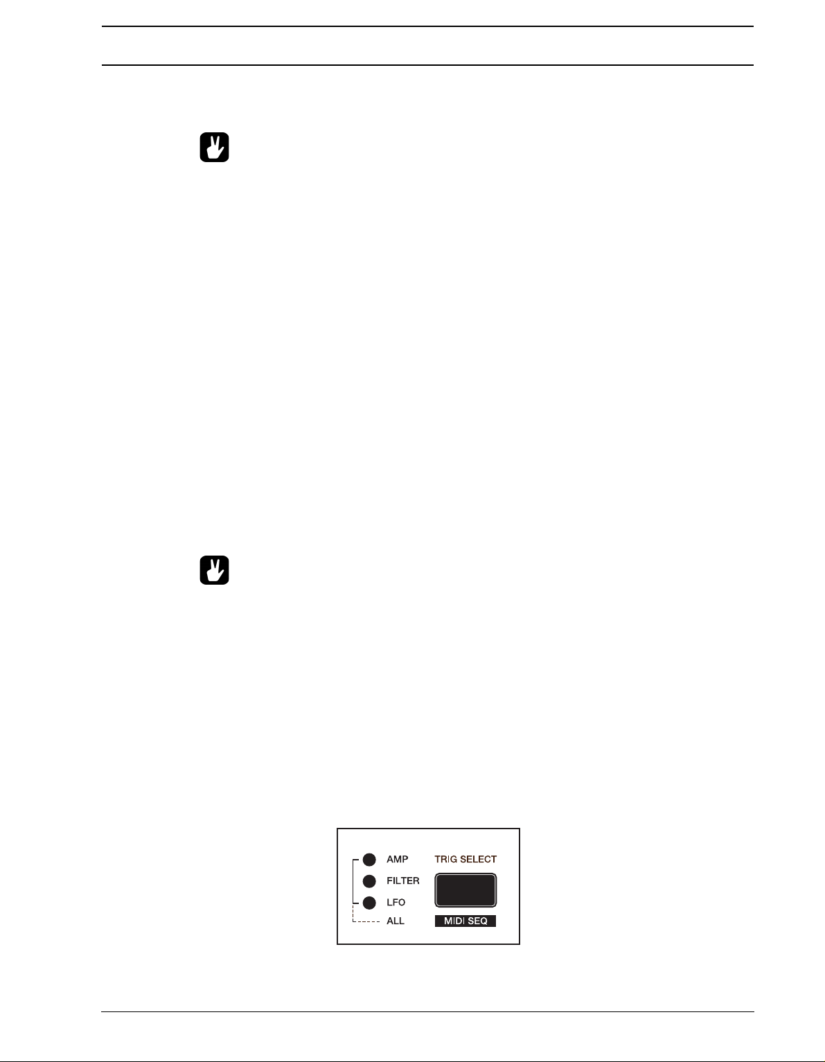
THE PATTERN SEQUENCER
note copy. Then hold the [TRIG] key for the step you want to paste the trig to, and press
[STOP] to perform the paste note operation.
• In GRID RECORDING mode, you can verify which steps have parameter locks by
looking at the <TRIG> LED’s. A firmly lit <TRIG> LED means that the corresponding step has no parameters locked, whereas a rapid interval flash indicates it does
have one or more parameter locks.
• A pattern can have a total of 62 individually locked parameters divided freely
etween all tracks and parameters. When a parameter is locked on one step, that
b
parameter can be locked to individual values on all the steps of the track.
PARAMETER LOCKS IN LIVE RECORDING MODE
In LIVE RECORDING mode, you can record parameter locks in real-time. To do this, follow
the steps below:
1. Begin with following the instruction in section “RECORDING PREPARATIONS”, on
page 46
2. To start recording in LIVE RECORDING mode, hold [REC] and then press [PLAY]. This
starts the sequencer recording and the record LED will start flashing.
3. Record parameter locks by adjusting the corresponding DATA ENTRY knob while the
sequencer is playing and recording. When changing a parameter, the parameter lock will
be set to the next trig step played on the track. If a parameter is not changed between
two trigs no parameter lock will be recorded for that step.
4. To remove parameter locks you need to enter GRID RECORDING mode and follow the
instructions in “PARAMETER LOCKS IN GRID RECORDING MODE” on page 56
• It is often a good idea to edit and fine tune the parameter locks in GRID RECORD-
ING mode, after recording them in LIVE RECORDING mode.
ADVANCED SEQUENCER CONTROL
For users that seek the most control over the creative process the Monomachine offer
unique sequencer features for fine tuned sequencing.
TRIG TRACKS
For each track you have access to three individual sub tracks named trig tracks, offering
individual control over the amplitude envelope, the filter envelope and the LFO trigs. This
means you can separate pitch changes from envelopes and LFO trigging, allowing for very
in-depth track sequencing.
57
Page 66

THE PATTERN SEQUENCER
Traditionally synthesizers retrig all envelopes when a NOTE ON event (a key pressed on
the keyboard) occurs. In the Monomachine NOTE ON events can be split up, allowing you
to trig the amplitude envelope (AMP trig),filter envelope (FILTER trig) or the LFO’s (LFO
trig) at any step of the sequence. Please refer to the first two illustrations in Figure 7, “Trig
track illustrations,” on page 59.
The [TRIG SELECT] key cycles between which trig track is being programmed, and the
<TRIG TRACK> LED’s indicate the current active selection. All three <TRICK TRACK>
LED’s lit means the ALL mode, where trigs for all three trig tracks are set. The four states
are listed below:
• ALL - T
pressed add or remove trigs on all three Trig tracks, and a pitch is added as default.
his is the default state where all <TRIG TRACK> LED’s are lit. [TRIG] keys
• AMP - Only adds or removes trigs on the AMP Trig track. No pitch is added as default.
• FILTER - Only adds or removes trigs on the FILTER Trig track. No pitch is added as
default.
• LFO - Only adds or removes trigs on the LFO Trig track. No pitch is added as default.
When trig track AMP, FILTER or LFO is selected, the <TRIG> LED’s are lit red if a trig is set
for the corresponding step on the trig track selected. The <TRIG> LED’s are green if the
trig is not set for the trig track selected, but on some other trig track (or if it has a Trigless
Trig, see section “TRIGLESS TRIGS”, on page 58). For example, a FILTER trig will be indicated with a green <TRIG> LED when the AMP trig track is active, given an AMP trig is not
placed on the same step.
When Trig Track ALL is selected, the <TRIG> LED’s are lit red if a trig is set on all AMP,
FILTER and LFO Trig Tracks. If one or more of them are missing then it is lit green. Steps
with NOTE OFF events are lit yellow.
TRIGLESS TRIGS
It is possible to change pitch or make parameter locks, even without trigging any envelopes. But since pitch and parameter locks are set with a [TRIG] key pressed, and trigs are
added when the [TRIG] key is pressed you need to insert a trigless trig first.
58
The quickest way to do this is to press the [TRIG] key twice while holding [FUNCTION].
The corresponding <TRIG> LED will then first turn yellow (NOTE OFF) and then green
which indicates it is a trigless trig. You can now hold the [TRIG] key and program a pitch or
parameter lock as normal, but no envelopes will be trigged. You can add these later using
the trig track functions as described in the previous section.
Normal trigs can also be converted into trigless trigs by removing the AMP, FILTER and
LFO trigs manually using the trig track functions.
PITCHLESS TRIGS
You can easily remove the pitch from a trig by pressing [EXIT/NO] while holding the [TRIG]
key. The pitch from the previous note will then continue to sound for the trig.
Page 67
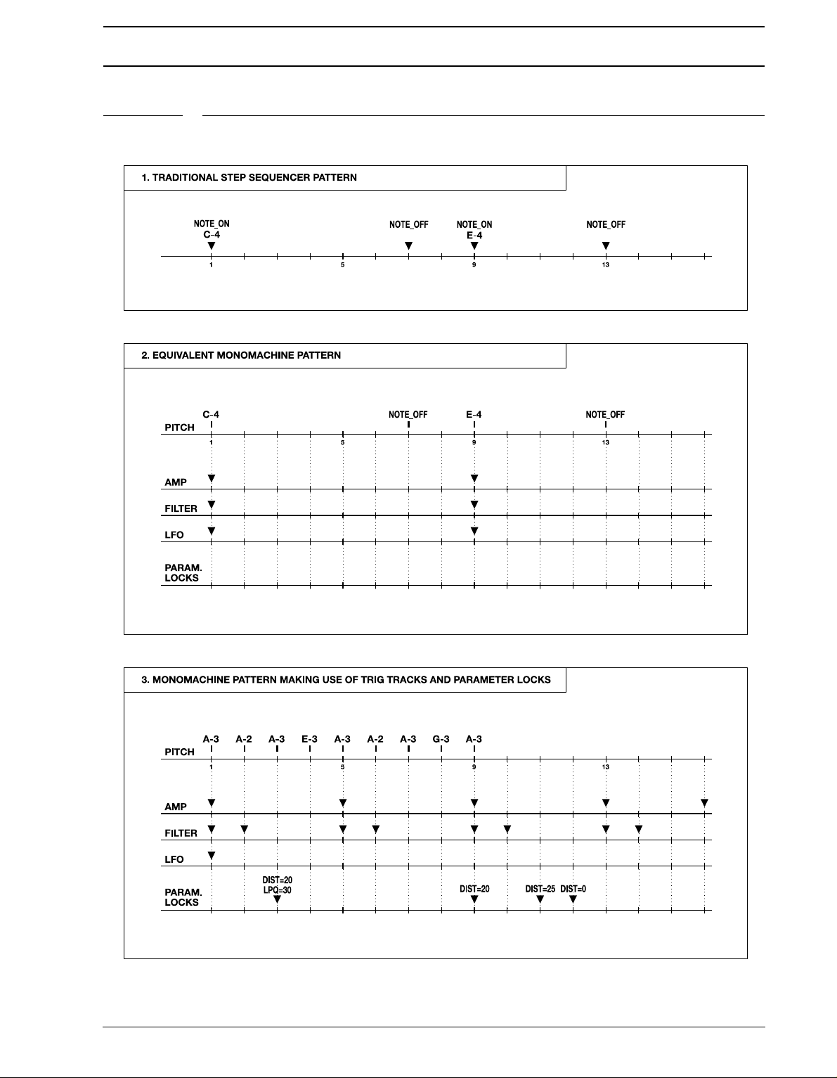
THE PATTERN SEQUENCER
FIGURE 7. Trig track illustrations
59
Page 68
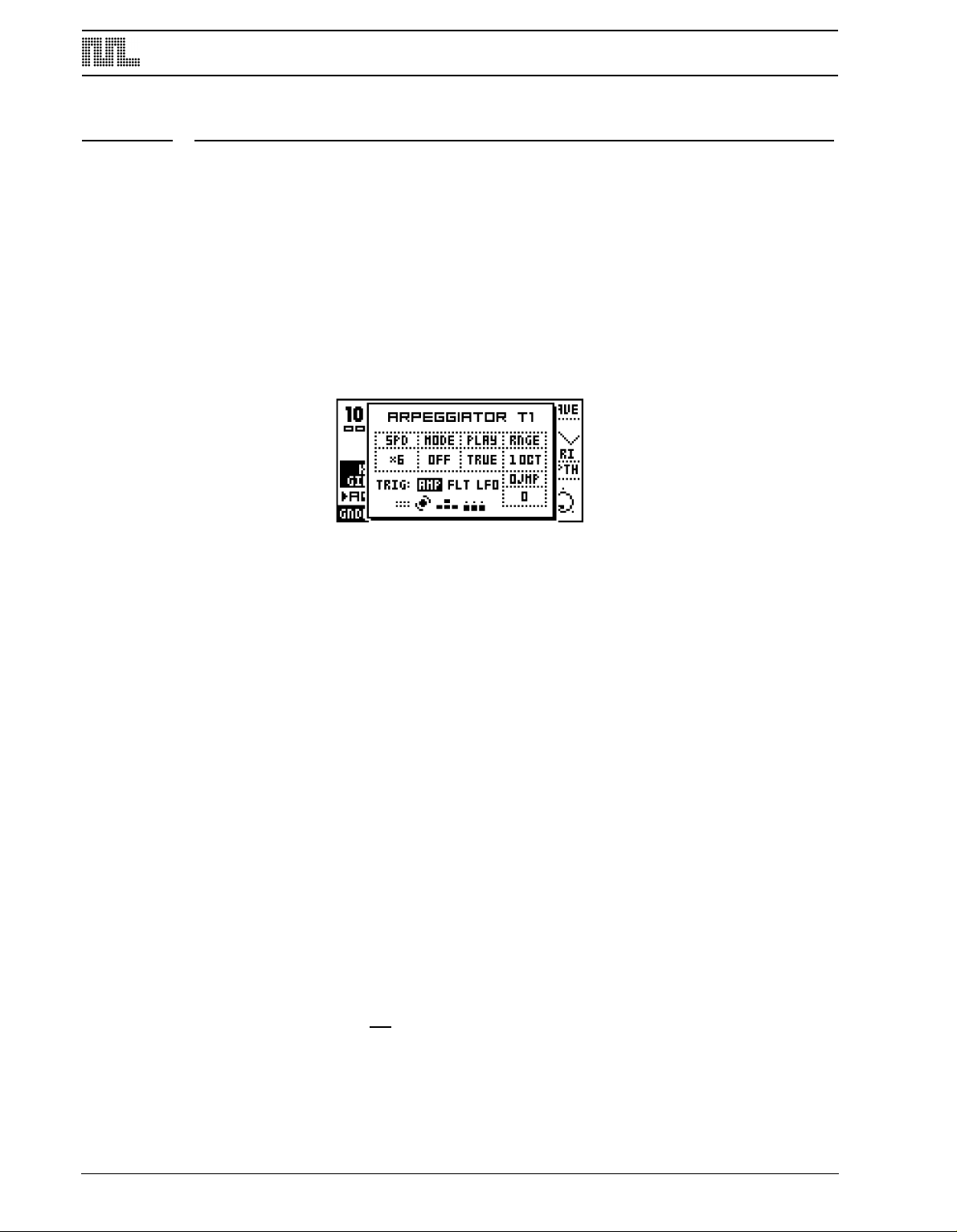
ADDITIONAL SEQUENCER FEATURES
ADDITIONAL SEQUENCER FEATURES
THE ARPEGGIATOR
Each track of the Monomachine (including the MIDI sequencer tracks) offers an advanced
arpeggiator. The arpeggiator is a note processor that generates rhythmic note patterns
from the arpeggiator settings and notes played. Most commonly arpeggiators are used for
making automated real-time monophonic cycled notes based on the chord played.
ARPEGGIATOR BASIC SETTINGS
Each pattern offers 12 arpeggiators, one per track.
1. The arpeggiator window is opened by pressing [
2. Select the track you want to edit the arpeggiator for using the [TRACK] keys.
Press [MIDI SEQ] while holding [FUNCTION] to edit the MIDI sequencer arpeggiators (see
page 60 for more information on the MIDI sequencer).
The parameters are controlled using the DATA ENTRY knobs A-D and H.
SPD (speed) sets the speed of the arpeggiator. It is synchronised to the global tempo. A
speed setting of 6 equals one 16th note, 12 equals 8th and so on.
MODE (mode) selects between four arpeggiator modes. Assuming you start with a uninitialised arpeggiator, you need to change the MODE from the the default value OFF to
either KEY, SID or ADD.
• OFF - D
eactivates the arpeggiator.
ARP] while holding [FUNCTION].
• KEY - The arpeggiator operates on the keys currently played. This is the way an
arpeggiator traditionally works. When the first note is pressed the arpeggiator is activated and start playing the note repeatedly with the timing specified by the SPD parameter. When more notes are added the arpeggiator cycles between playing them. When
keys are released they are removed from the arpeggiator cycle. When all keys are
released the arpeggiator stops.
• SID - Keys pressed stay in the arpeggiator cycle even after a NOTE OFF command.
This mode replicates the operation of the arpeggiator of the SidStation synthesizer.
When only one key is pressed the arpeggiator is not activated. When more than one key
is pressed the arpeggiator is activated and start playing the notes in cycle. When keys
are released they are not removed from the cycle, but continue being played. The notes
stay in the cycle until a new note is pressed. This way an arpeggiated chord can be held
without keys being pressed down, while preparing for another chord. Stop the arpeggiato
by pressing either one single key or pressing [STOP].
• ADD - In this mode no notes are removed from the arpeggiator cycle until all keys are
eleased. The arpeggiator start when the first key is pressed, and more notes can be
r
60
Page 69

ADDITIONAL SEQUENCER FEATURES
added to the cycle by pressing and releasing keys while still at least one key is pressed.
This way you can build up large note-cycles quickly in auto-play sequencer style. The
arpeggiator stops when all keys are released.
PLAY (play direction) selects between five modes of arpeggiator playback.
• TRUE - T
he arpeggiator plays the notes in the same order they were played.
• UP - The arpeggiator sorts the notes and plays them upwards, in rising order.
• DOWN - The arpeggiator sorts the notes and plays them downwards, in descending
order.
• CYCLE - T
downwards.
he arpeggiator sorts the notes and plays them cycling first upwards then
• RND - The arpeggiator plays the notes in random order.
RNGE (octave range) controls the octave range. If the parameter is set higher than the
default “1 OCT”, the arpeggiator will repeat the cycles in higher octaves repeatedly up to
the specified setting.
OJMP (octave jump) tells the sequencer where in the arpeggiator chord the octave jump is
made. '0' means after the full chord has played. '1' means one step before the end of the
chord. '2' means two steps before the end of the chord and so on.
• To activate the arpeggiator in a track, enter chords!
• To activate the arpeggiator on the SFX-60MKII module without an external MIDI
keyboard added, you can hold [FUNCTION] while pressing the [TRIG] keys.
• Copy, clear, paste and undo functions are available to the arpeggiato settings
using [FUNCTION]+[REC]/[PLAY]/[STOP]
• To create computer-game-like arpeggiato chords, set SPD to a low value, select
ode SID and turn off AMP FLT and LFO trigging as described in the section
m
below.
ARPEGGIATOR ENVELOPE TRIGGING SWITCHES
You will find three switches that control the envelope trigging of the arpeggiator below the
four parameters described in “ARPEGGIATOR BASIC SETTINGS“. You move the focus
square to the right of the “TRIG:” label with the [LEFT] and [RIGHT] keys, and adjust the
settings with [UP] and [DOWN].
• AMP = Amplitude envelope
• FLT = Filter envelope
• LFO = LFO envelope
If the label is displayed the envelope trigging connection is switched ON, and if “---” is
shown it is switched OFF. If trigging is ON for an envelope, it will be trigged for each note
played by the arpeggiator. All envelopes are always trigged when the first note of the
arpeggiato is played.
61
Page 70
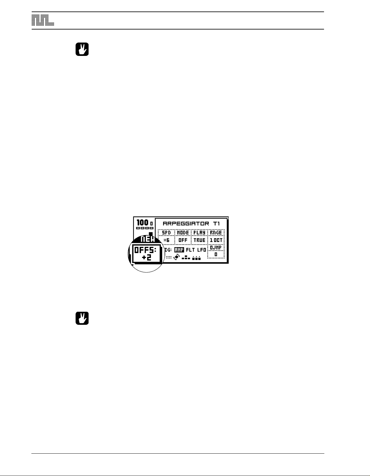
ADDITIONAL SEQUENCER FEATURES
• It can be useful to turn all envelope trigging off for fast arpeggiato speeds, and
allow the envelopes to give the impression of the arpeggiated chord as one
sound.
• If you are using a trigged LFO for a slow modulation of a parameter it can be use-
ful to turn off LFO Envelope Trigging in the arpeggiator to let the LFO modulate
without being restarted for each note.
• The envelope trigging switches are not available in the MIDI sequencer arpeggia-
ors, as MIDI do not allow for such type of extended control.
t
ARPEGGIATOR RHYTHM AND OFFSET TRACK
The arpeggiator offers a rhythm and offset track of up to sixteen steps. This can be used to
make rhythmic arpeggiator patterns, one-finger melodies or very wild out-of-control
arpeggiator patterns.
By default the rhythm and offset track is eight steps of length. The LEVEL knob is used for
adjusting the length of the track. The length is indicated by the <TRACK> LED’s being lit
up.
Green LED’s indicate that the arpeggiator is active for the step. Red LED’s will be will mute
out the arpeggiator for that step. Use the [TRIG] keys for switching the steps.
By holding a [TRIG] key and using the [UP] and [DOWN] keys, you can adjust the note offsets for the active steps. The current offset is displayed while the [TRIG] key is held in a
small popup-window in the lower left corner of the LCD.
• Given the flexibility of the arpeggiator, you can think of it as a mini-sequencer
within a sequencer. Using different SPD values and lengths of the rhythm and offset track can greatly affect the rhythmic structure of a pattern.
TRANSPOSE
Each track of the Monomachine (including the MIDI sequencer tracks) offers transpose settings. Transposing in the Monomachine is made real-time and the pattern data programmed is not affected.
62
1. The transpose window is opened by pressing [TRANSPOSE] while holding [FUNC-
TION].
Page 71
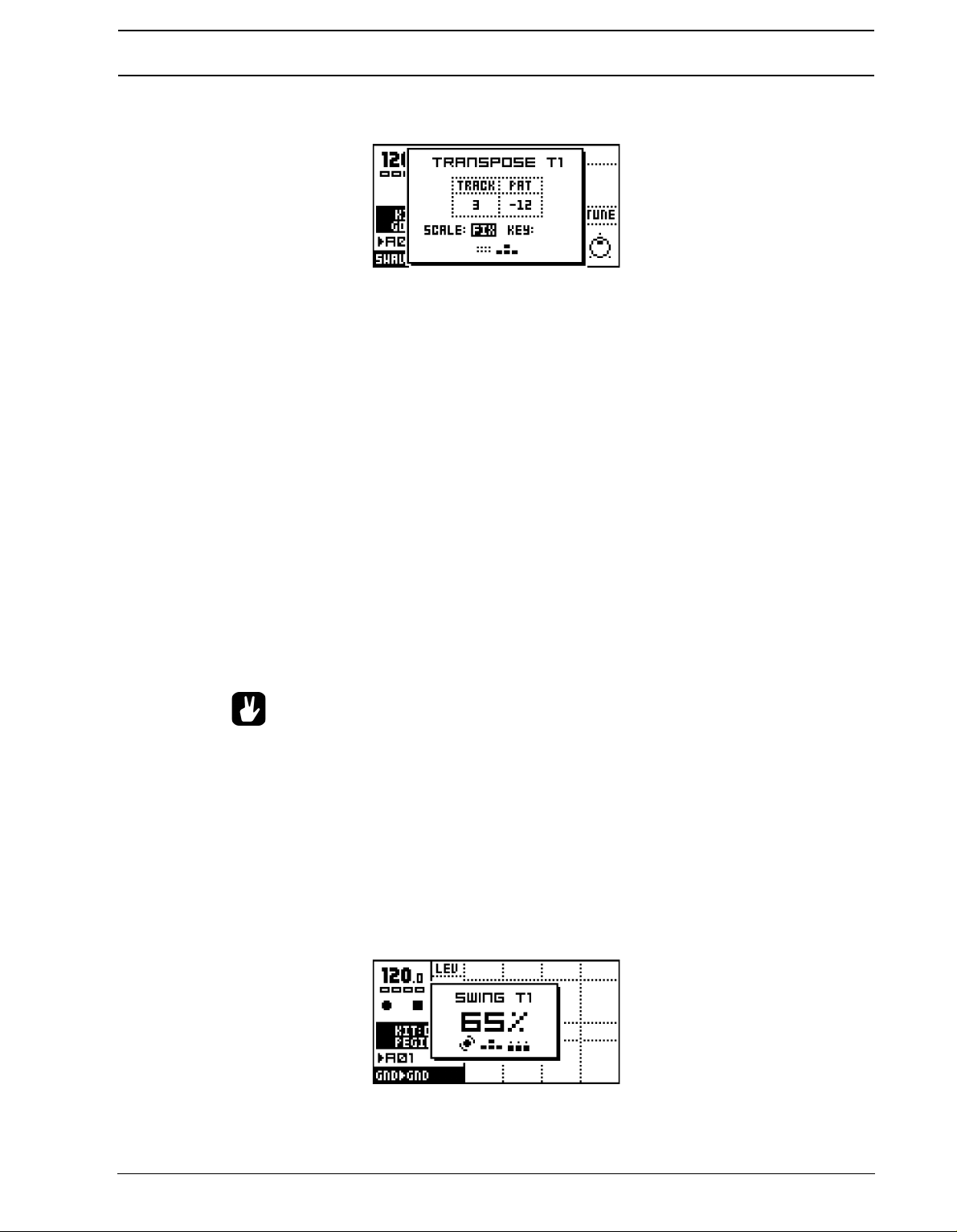
ADDITIONAL SEQUENCER FEATURES
2. Select the track you want to edit the transpose settings for using the [TRACK]
TRACK (track transpose) sets the individual track transpose in semitones for the selected
track. The parameter is controlled with DATA ENTRY knob A.
PAT (pattern transpose) controls the transpose setting for the full pattern. This parameter is
the same for all tracks. Use the DATA ENTRY knob B on the first row to alter the transpose
amount.
SCALE (scale) is set per track. To alter this parameter, move the inverted focus square
with the [LEFT] and [RIGHT] keys, and adjust the settings with [UP] and [DOWN].
• ---
- The notes are transposed the exact amount of notes specified by the sum of the
track, pattern, song and multi trig transpose. This is the normal mode. No KEY value can
be set.
keys.
• FIX - Only the track transpose is used for transposing. No KEY value can be set.
• MAJ - The transposed notes are kept within the Major scale specified by the KEY value.
• MIN - The transposed notes are kept within the Minor scale specified by the KEY value.
KEY (key) is only available for certain SCALE selections and defines in which key the MAJ
and MIN scale selections will be.
• Set SCALE to “FIX” for tracks playing percussive sounds. If the track is trans-
posed in a song or using multi trig transpose the percussion will then keep its
sound while melodic tracks are transposed.
SWING
Swing can be used for adding shuffle, or other sub-step rhythmic adjustments to a pattern.
The swing settings are saved as part of the pattern.
1. The SWING window is opened by pressing [SWING] while holding [FUNCTION].
2. Select which track you want to edit the swing settings for using the [TRACK] keys.
Use the LEVEL knob to control the swing amount. The swing amount is set between 50%
and 80%. 50% is the default value which makes the pattern unaffected by swing, and the
63
Page 72
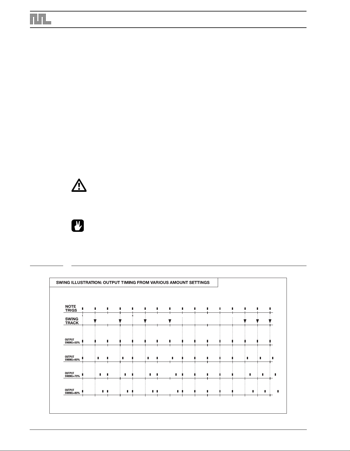
ADDITIONAL SEQUENCER FEATURES
9 13
maximal value is 80%. The swing amount parameter is the same for all the tracks of the
pattern. Each track however has its own swing track.
Green <TRIG> LED’s indicate the steps that will be time-shifted by swing, and the [TRIG]
keys are used to switch their state. Use the [SCALE] key to cycle between the pages.
THE SWING TRACK
As default, the swing is programmed to shift every second 16th note, starting on step 2.
This is how the swing pattern will be restored after a pattern clear operation (see page 53)
or swing clear operation. This gives the traditional “shuffle”-style swing for a 4/4 normal
speed pattern.
In double speed mode (see page 54) you need to modify the swing pattern to get the same
result as was given by the default swing pattern in single speed mode, activate swing for
every fourth note, starting with the third note.
Please check figure ”Swing example” below for an example of the swing effect with different swing amount and swing track settings. The first eight steps use the default “shuffle”
setting and the last eight use an edited swing track setting.
• When the Monomachine is locked to external MIDI clock, the swing amount will be
quantised to the resolution of the MIDI clock, leaving only four effective swing
amounts.
• Copy, clear, paste and undo functions are available on the swing tracks using
[FUNCTION]+[REC]/[PLAY]/[STOP]
FIGURE 8. Swing example
64
Page 73
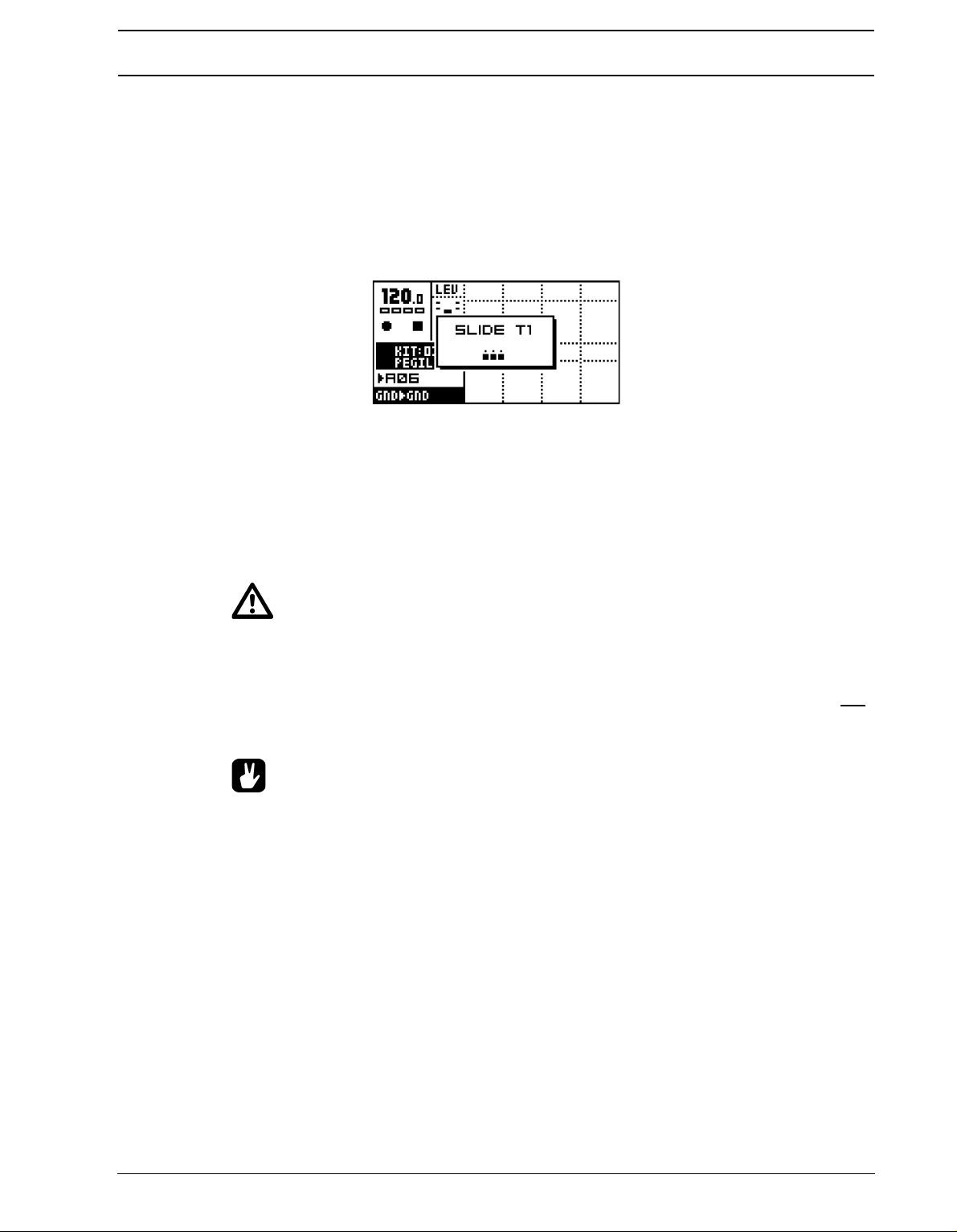
ADDITIONAL SEQUENCER FEATURES
SLIDE
The default behavior for parameter locks is that the value changes exactly when the step is
layed. By using the slide function, the parameter value changes made by parameter locks
p
can be slid smoothly between the locked values. The slide tracks are saved as part of the
pattern.
1. The SLIDE window is called by pressing [SLIDE] while holding [FUNCTION].
2. Select the track you want to edit the slide track for using the [TRACK] keys.
The <TRIG> LED’s indicate which steps will slide, and the [TRIG] keys are used to switch
their state. If your pattern is longer than 16 steps, use the [SCALE] key to cycle between
the pages.
For a parameter to slide it needs to be locked at two steps. If the slide track is set for the
same step as there is a parameter lock, the parameter will slide to the next value it is
locked to. The speed of the slide is relative to the current tempo. The slide is always completed exactly when the next step with the same parameter locked is reached.
• Only parameters locked on the steps selected in the slide track, and on a later
step, will slide. Parameters that are unlocked, or only locked at one step will not
slide.
• If there are trigs in between the two locked parameter where the parameter is not
locked, the parameter will slide between the two locked positions and is not interrupted by the unlocked trigs in the middle.
• Copy, clear, paste and undo functions are available on the slide tracks using
[FUNCTION]+[REC]/[PLAY]/[STOP]
The figure ”Slide illustration” below show an example of how the slide track influence a
locked parameter. The first slide trig makes the parameter slide to the next locked parameter value. Even though there is a trig in the middle it does not interrupt the slide. When the
destination is reached the locked value is held and not slid, as there is no slide trig for that
position. For the last three slide trigs, it is only the middle one that is causing any slide, as
the other slide trigs do not have any parameter locked at the same step.
65
Page 74

ADDITIONAL SEQUENCER FEATURES
NOTE
TRIGS
1 5 9 13
SLIDETRACK
PARAM.
LOCK
PARAM.
OUTPUT
SLIDE ILLUSTRATION. NORMAL (UNLOCKED) PARAMETER VALUE = 0
FIGURE 9. Slide illustration
THE MUTE MODE
Track muting is normally performed by pressing the [
TION]. The Monomachine offers an additional interface for controlling the track muting.
When one hand operation is preferred, or when you want simultaneous access to both the
internal and the MIDI sequencer mute tracks at once, the MUTE window is the solution.
The the MUTE window by pressing [BANK] while holding [FUNCTION].
The six first boxes refer to the six internal Monomachine tracks. In the window above all
tracks are un-muted. The six last boxes refer to the six MIDI sequencer tracks. Toggle the
Monomachine tracks between muted and un-muted using [TRIG] keys 1-6. The MIDI
sequencer tracks are reached through the [TRIG] keys 9-14. A muted track will be displayed as a “-” sign. The corresponding <TRIG> LED indicate the Mute-state of the track. If
it is lit the track is not muted.
TRACK] keys while holding [FUNC-
66
Page 75

ADDITIONAL SEQUENCER FEATURES
In addition to the <TRIG> LED’s, the Mute-state is indicated in the MUTE window. Boxes
means that the track is un-muted, and a dash means it is muted. The <TRACK> LED’s will
also be updated.
If you press the [TRIG] keys while holding [FUNCTION] the mute change is held until
[FUNCTION] is released. A track that is currently muted but will be un-muted when [FUNC-
TION] is released is displayed as a “+” sign. A track that is currently not muted but will be
muted when [FUNCTION] is released is displayed as an “X” sign.
MINIMISING THE MUTE WINDOW
While working in MUTE mode, the MUTE window hide large parts of the main interface
screen. This can be disturbing if you want to work with mutes at the same time as accessing the sound parameters.
To avoid this problem, the MUTE window transforms to a small centered window when a
DATA ENTRY knob is accessed while in MUTE mode. To return to the big MUTE window,
press the [ENTER/YES] button.
• The mute works on note level. That means that sounds already trigged will con-
tinue sound, but further trigs will be masked. This allows sounds to fade out in a
natural way.
• The track mutes are true global parameters, just like tempo. A muted track
remains muted, even when the pattern is changed or song mode is entered or
exited.
67
Page 76

ADDITIONAL SEQUENCER FEATURES
POLY MODE
In normal operation the Monomachine offers six tracks of multitimbral monophonic sound
ynthesis. Ensemble machines (see Appendix A for more information) can be used to
s
make up to four notes chords using only one track, but for using the other machines polyphonically you need to enter the POLY mode.
1. Press [POLY] while holding [FUNCTION] to enter POLY mode. The POLY mode is indi-
cated by both the <PATTERN> and <SONG> LED’s being lit.
In POLY mode all six Monomachine sound engines polyphonically generate the sound of
only one track. All tracks beside the one currently selected with the [TRACK] keys are disabled. The currently selected track instead offers six notes of polyphony.
• In POLY mode, the internal sequencer operates polyphonically. You can use
chords to generate polyphonic chords. Just remember that all other tracks except
the one currently selected are disabled while in POLY mode.
68
Page 77

THE MIDI SEQUENCER
THE MIDI SEQUENCER
Each of the six internal sequencer tracks of the Monomachine sequencer is teamed with a
MIDI sequencer track for controlling external MIDI gear. The six MIDI sequencer tracks are
part of each pattern and operate individually, although with a few connections with the internal tracks since the LFO’s are shared between the internal tracks and the MIDI sequencer
tracks. The MIDI tracks play simultaneously and synchronised with their internal counterparts.
1. Switch between internal sequencer and MIDI sequencer editing by pressing [
while holding [FUNCTION].
2. MIDI track editing is indicated by all the <TRIG TRACK> LED’s being unlit, and the four
uppermost <DATA PAGE> LED’s lit.
USING THE MIDI SEQUENCER
The Monomachine MIDI Sequencer is used almost identically to the internal sequencer.
The main difference being that no internal sound is generated, data is only transmitted on
the MIDI OUT port, for controlling external MIDI gear.
Use the [TRACK] keys to select the MIDI track you wish to edit. Note that MIDI tracks are
muted separately from the internal tracks with the [TRACK] keys while holding [FUNC-
TION], or through the special MUTE mode interface (see section “THE MUTE MODE”, on
page 66).
To use the MIDI sequencer you need to connect the MIDI OUT port of the Monomachine to
the MIDI IN port of another MIDI device. The external MIDI device needs to listen to the
MIDI channel of the Monomachine MIDI track in focus. The keyboard, [TRIG] keys and
MIDI sequencer output of the track is now directed to the MIDI channel selected in the Global “MIDI SEQUENCER SETTINGS” menu page (see section “MIDI SEQ SETTINGS”, on
page 104 for more information).
MIDI SEQ]
Please refer to sections “GRID RECORDING” on page 46 and “LIVE RECORDING” on
page 48 for information on how to input notes in the sequencer.
• Chords can be entered in the MIDI sequencer, but all notes of the chord need to be
the same length. If you want to play true polyphonic notes you need to make use
of several tracks and direct the output to the same MIDI channel.
• Parameter locks can be used by the MIDI sequencer, which is very handy to con-
trol for example the filter cut off parameter of an external synth.
69
Page 78

THE MIDI SEQUENCER
THE MAIN MIDI SEQUENCER INTERFACE
LEN (note length) sets the maximum time the note will be played until a NOTE OFF is sent.
Notes can also be interrupted with NOTE OFF trigs (set by pressing a [TRIG] key while
holding [FUNCTION]). If you prefer to stop notes with only NOTE OFF trigs, set LEN to the
maximum value. Notes will then have infinite length. Use parameter locks to set different
note lengths for different steps.
VEL (velocity) controls the MIDI velocity sent for each note. Use parameter locks to set different velocity values for different steps.
PB (pitch bend) controls the MIDI pitch bend setting.
PCHG (program change) can be used for outputting MIDI program change commands, in
order to change the patch of the external MIDI device. The PCHG parameter only transmits
data when parameter locked. It is not possible to slide this parameter.
CC 1-4 (control change 1-4) set the control change parameter values. Which parameters
that are used is set in the Global “MIDI SEQUENCER SETTINGS” menu page (see
page 104 for more information).
COMPARISON WITH THE INTERNAL SEQUENCER
The MIDI sequencer tracks function to some degree like their internal counterparts. Below
is a list of similarities and differences:
• The MIDI sequencer tracks do not offer any trig tracks, since MIDI does not allow for
s
uch type of extended control.
• The MIDI sequencer offers six additional arpeggiators with individual settings, but they
do not offer any envelope trigging switches for the same reason as mentioned above.
• The MIDI sequencer tracks offer individual swing and slide tracks, but the swing amount
is a common parameter for the pattern.
• The MIDI sequencer offers individual track transpose, but the pattern transpose is a
common parameter for the whole pattern.
• The MIDI sequencer tracks share the LFO’s with their equally numbered internal
sequence tracks.
• The settings of the main MIDI sequencer interface is stored as part of the kit. If you
make changes to the parameters you need to save the kit in order to keep them.
70
• The internal sequencer also transmits MIDI. If you want more tracks for controlling
external MIDI gear you can mute the audio output of internal tracks, enable MIDI
output and use them only for controlling external gear, extending the six MIDI
Page 79

THE MIDI SEQUENCER
sequencer tracks. Read more about how to configure the MIDI output of the internal sequencer in section “CONTROL OUT1”, on page 90. Note though that the
same parameters won’t be available. Note off commands are also handled different when MIDI sequencing using the internal tracks. On the internal tracks you
need to insert a NOTE OFF trig. For more info about NOTE OFF trigs, see “OVERVIEW OF GRID RECORDING MODE” on page 11.
• The Monomachine makes distinction between MIDI sent out of the unit and MIDI
eceived. Even if the same MIDI channel is selected for one track of the MIDI
r
sequencer and the one track of the internal sequencer, the MIDI sequencer will not
control the internal sounds, as the MIDI sequencer data is only going out through
the MIDI OUT.
• As the MIDI sequencer tracks are part of the pattern, they will also be played as
art of the multi trig and the sequence start playback options. This allows tight
p
integration of external MIDI gear in a Monomachine performance.
71
Page 80
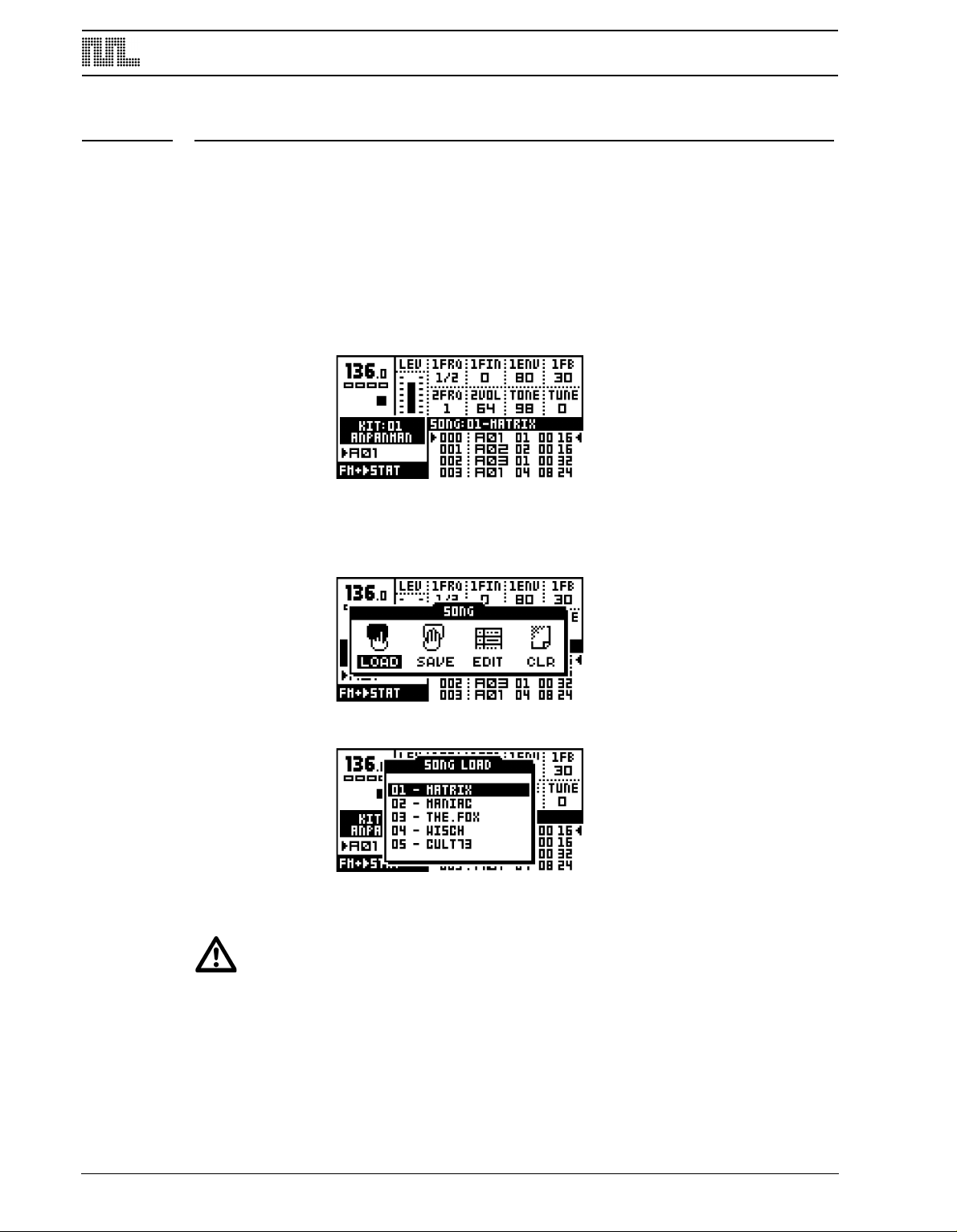
THE SONG MODE
THE SONG MODE
The Monomachine song sequencer is a tool for setting up sequences of patterns. Each
song row can have unique settings for selected parameters such as pattern start, offset
and length, repeats, tempo, mute information, and transposes. The song mode can be
used for making a fully arranged song or for setting up looped sets of patterns for live use.
A song can have up to 200 rows, and there are 24 song slots.
To enter SONG mode by press the [PATTERN/SONG] key, so that the <SONG> LED is lit.
The screen will change to make room for the song list.
LOAD SONG
1. To load a song, you first need to open the SONG window by pressing the [KIT/SONG]
ey.
k
2. Use the [ARROW]
3. Choose the song you wish to load by using the [UP] and [DOWN] arrow keys. Press
keys to move the focus to the LOAD icon and press [ENTER/YES].
[ENTER/YES] to load the song.
• Loading a song will destroy any unsaved changes to the current song. Make sure
to store unsaved work you wish to keep before loading a new song.
72
Page 81

THE SONG MODE
SAVE SONG
1. Open the SONG window by pressing the [
keys to move to the SAVE icon.
KIT/SONG] key. Use the [LEFT] and [RIGHT]
2. Press [
3. In the menu, you find a list of the songs stored in memory. Use the [UP] and [DOWN]
ENTER/YES] to call the SAVE SONG menu.
keys to choose among the 24 song slots. Press [ENTER/YES] to select the slot where
you want to save your song.
4. A window opens where you can name the song.
Select characters using the [UP] and [DOWN] arrow keys or by using the LEVEL knob.
The [LEFT] and [RIGHT] keys move the cursor backwards and forwards on the line.
5. Holding the [FUNCTION]
key gives access to the “high score” selection method, in
which you see all characters at the same time. Keep the [FUNCTION] key held while
navigating using the [LEFT], [RIGHT], [UP] and [DOWN] buttons. Release the [FUNC-
TION] key, when you have found the right letter.
6. Once you are done naming the song, press [ENTER/YES] to save it.
7. If you want to exit without saving the song, press [EXIT/NO].
• The commands copy, paste, clear and undo are available in the SAVE SONG and
LOAD SONG menus.
73
Page 82
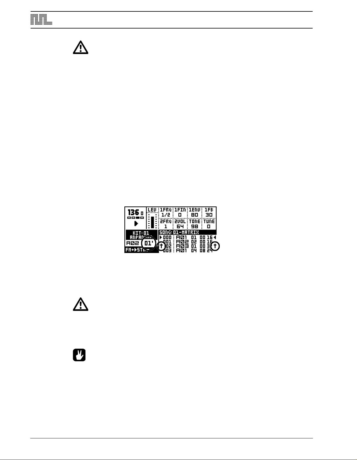
THE SONG MODE
• Accurate playback of a previous song depends on the patterns it uses being
unchanged since saving. Otherwise, the song will sound different.
SONG PLAY
To start playing a song, make sure that you are in SONG mode, and that a song is presently loaded or created.
1. Start the playback of the song by pressing [PLAY]. Pressing [PLAY] again pauses the
layback. To stop the playback, press [STOP].
p
2. At any time you may switch back and forth between the song and the pattern mode by
pressing the [PATTERN/SONG] key. The song pointer will be held until [STOP] is
pressed. This way you can hold the song replaying, looping a pattern in pattern mode,
until returning to song mode, continuing replaying the song at the position you left it.
SONG TRANSPORT
While playing a song, it is possible to freely navigate within the patterns of the song.
1. Use the [UP] and [DOWN] keys to move the two song pointer position indicators at the
left and right of the song list. They are shaped as two arrows. Press [ENTER/YES] to
move the playback position to the position of the arrows.
2. The arrows will flash and alternate between flashing toward the row and in the direction
f the current song position. When a song row is repeated the number of remaining
o
repeats flashes to the right of the current pattern index.
3. Once the current pattern has played to the end or the number of repeats has been com-
pleted the playback will continue from the row indicated by the arrows.
• The song is played to its end and then it stops. Of course, infinite loops make
never ending songs.
• If the song has tempo adjustments programmed the current global tempo will be
changed.
• Monomachine sends and recognises MIDI Song Pointer Position. This means that
you can control the position in the song list from an external sequencer, and you
can control an external sequencer from the Monomachine.
• [STOP] stops the playback, but holds the song pointer position. A second [STOP]
moves the song pointer position to the beginning of the song.
74
Page 83
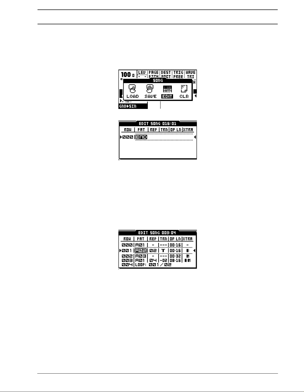
THE SONG MODE
SONG EDITING
The song editor is where the song is built. Here patterns are assigned to the song. The
behavior of the patterns is also set in the song editor.
1. Press the [
KIT/SONG] key to open the SONG window. Move the cursor to the EDIT icon
using the [ARROW] keys.
2. Press [
ENTER/YES] to open the EDIT SONG screen.
This is the main screen where you arrange your patterns into a song. You can edit the song
while it is playing. The two filled arrows on each side of one of the rows are the song position pointers. They indicate which song step the sequencer is currently playing. In the
header of the menu, next to the text “EDIT SONG” there is a counter, indicating how many
bars and beats the song has played.
Use the [UP] and [DOWN] keys to select the song row you wish to edit. The [LEFT] and
[RIGHT] keys allow you to move the focus between columns. The LEVEL knob alters the
value of each setting.
ROW (song row) is the amount of steps the song consists of. A song can consist of a maximum of 200 rows. The song is played from row 0 to the end row.
PAT (pattern) is the column which shows which pattern is assigned to the row. Set the pattern you want to be played on the song row using the LEVEL knob, or by pressing the
appropriate [BANK]+[TRIG] keys. You can also program loops in this column. See section
“SONG LOOPS”, on page 77 for more information on this. “END” marks can also be set
from this column. It can be found as the first item in the list of patterns, and marks the end
of the song, where the sequencer will be stopped.
REP (repeat) is the column where you control how many times the song row will be
repeated. Use the LEVEL knob to alter the number of repeats.
75
Page 84
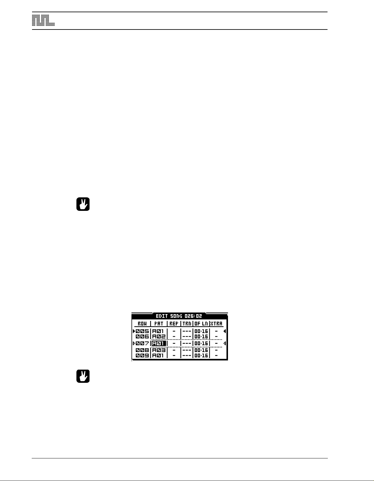
THE SONG MODE
TRN (transpose) sets a pattern transpose for the song row. Use the LEVEL knob to control
the value. By pressing [ENTER/YES] you enter the SONG TRACK TRANSPOSE window,
where individual transpose can be set for the tracks. If an individual song track transpose is
set for a row, it is indicated by a bold “T“ in the TRN column. You then need to enter the
SONG TRACK TRANSPOSE window to see both the pattern and the individual track transpose. See section “SONG TRACK TRANSPOSE”, on page 78 for more information on
song track transpose.
OF LN (offset and length) is a column that can be used to override the default start offset
and length settings for the pattern of the row. The default start offset of a pattern is always
zero as this means to start playing from the beginning. The default length is set from scale
setup (see section “SCALE SETUP”, on page 45). The song row offset and length functions can be used to build complex rhythm structures. It can also be used for exchanging
parts of a pattern, to add for example a fill in to the end of a pattern. Use the LEVEL knob
to control the settings.
XTRA (song extra) column can be used for setting song row mutes and song row BPM. If
any mute is set for the row, it is indicated by a bold “M” in the XTRA column. If a new BPM
is set for the row, it is indicated by a bold “B”. Press [ENTER/YES] to enter the SONG
EXTRA menu. Please see section “SONG EXTRA”, on page 78 for more information.
• To insert a row in the song, use [FUNCTION] together with the [DOWN] key.
• To remove a row in the song, use [FUNCTION] together with the [UP] key.
• Copy, paste, clear and undo functions operate on rows in song edit
SONG EDIT TRANSPORT
It is possible to start playback from any row position in a song.
1. Move the editing focus to the row you wish to start the playback from and press the
ENTER/YES] button.
[
2. If the song is currently playing when you select another row, you will see two hollow
arrows on each side of the newly selected row. They indicate that the selected row will
play next once the current row reaches its end.
• In the right part of the title bar the current song pointer position is displayed in
bars and beats. This information is also updated when a new song pointer is set
with [ENTER/YES]. This information can be used for synchronising the Monomachine song construction with the song of another sequencer.
• Use the loops and jumps to creating a live setup.
76
Page 85
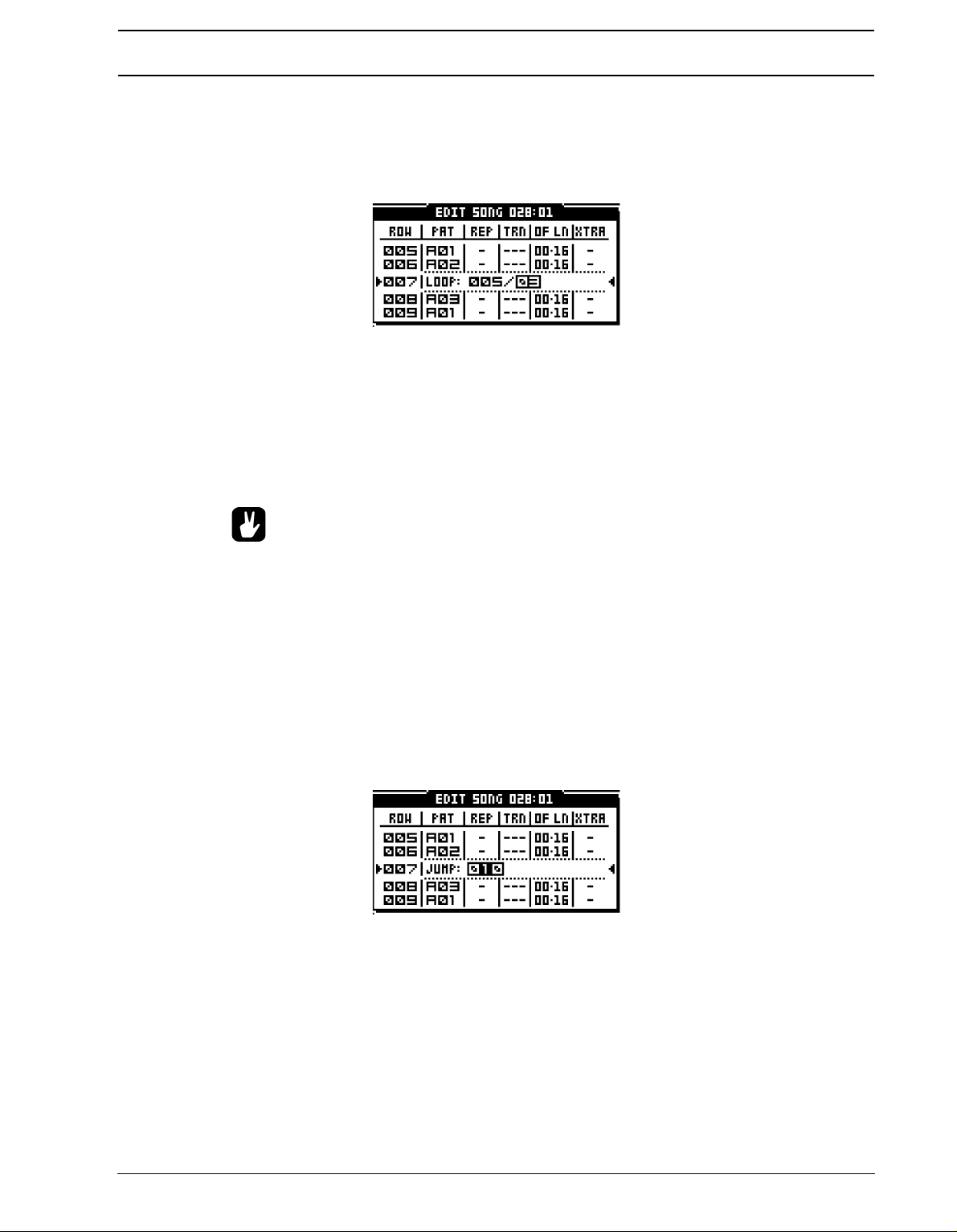
THE SONG MODE
SONG LOOPS
Song loops are a useful tool when creating a song. By using this command you can limit
the number of rows and make the structure of the song clearer. They can also be used for
setting up pattern loops in order to extend the limit of maximum 64 steps per pattern.
To create a loop, turn the LEVEL knob in the PAT column to the position right before the
A01-pattern, after the END indicator. Use the [LEFT] and [RIGHT] keys to navigate
between the different columns.
When a loop is selected the second edit column controls which row to jump back to. Use
the LEVEL knob to control this. The third column selects how many times the loop should
be repeated.
• Loops can be nested (that is, loops within other loops).
• A set of infinite loops can be very useful in a live setting. With a set of infinite
loops, the song transport functions can be used to jump between the looping patterns.
SONG JUMP
A loop can be converted into a forward jump. Insert a jump by turning the LEVEL knob so
that the number of the second loop row becomes a number that is greater than the current
row number. The jump command will appear and no loop count column will be available.
Use the [RIGHT] arrow key to move the focus to the column where you insert which song
row you want the song position pointer to jump to.
SONG HALT
If you set the loop to jump to the current row it will change to a HALT statement. When the
song pointer reaches a HALT statement it will pause the playback. You then need to use
77
Page 86
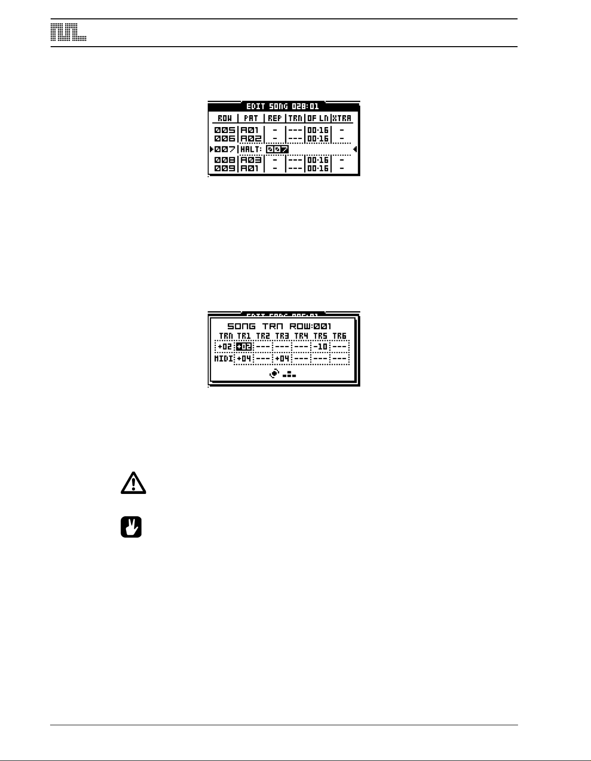
THE SONG MODE
the song transport controls as described in “SONG EDIT TRANSPORT” on page 76 to
select a new position to start from.
SONG TRACK TRANSPOSE
Here the transpose settings for the patterns in a song are controlled.
1. By pressing [ENTER/YES]
in the transpose column of the EDIT SONG window you
reach the SONG TRACK TRANSPOSE menu.
2. Use the [RIGHT] and [LEFT] keys to move between the columns, and also to reach the
lower row. Use LEVEL to update the parameter values. Use the [UP] and [DOWN] keys
to move between the song rows. Press [EXIT/NO] to exit the SONG TRACK TRANSPOSE window.
TRN (pattern transpose) control the pattern transpose.
TR1..6 (track 1-6 transpose) controls the individual track transpose for the six internal Mon-
omachine tracks. The six parameters on the MIDI row control track transpose for the six
MIDI sequencer tracks.
• The track transpose settings made are only valid on that particular row.
78
• If individual track transposes are set for a row, the transpose value in the EDIT
SONG window is exchanged for a bold “T”. You then need to enter the SONG
TRACK TRANSPOSE window to check the settings.
SONG EXTRA
The SONG EXTRA window is the interface for controlling song row mutes and song row
BPM settings.
Page 87
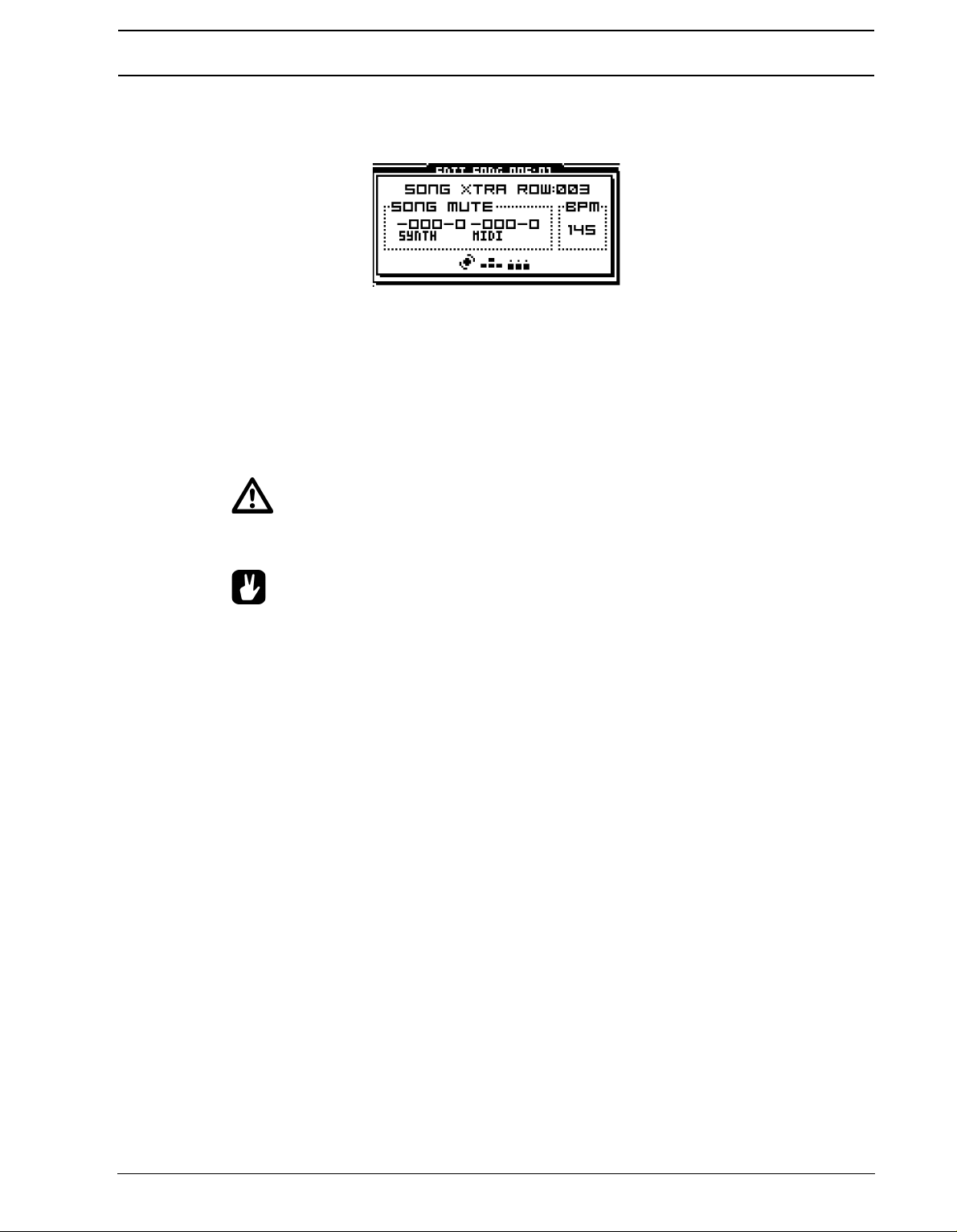
THE SONG MODE
1. Reach it by pressing [ENTER/YES]
window..
From here you can set the mutes for the song row. Use the [TRIG] keys 1 to 6 to set the
mute mask for the internal tracks, and [TRIG] keys 9 to 14 for the MIDI sequencer tracks. A
muted track will be displayed as a “-” sign.
Tempo adjustments can be programmed by setting a BPM value. Use the LEVEL knob to
update the BPM setting. You need to start by increasing the assigned BPM-value. To
remove the BPM value, turn the LEVEL knob so that the lowest possible value is selected.
You will then see “-” printed in the BPM tab.
in the SONG EXTRA column in the EDIT SONG
• If no BPM value is set for the step, the current tempo is used. If a song does not
have any tempo settings, the current tempo is used for the full song.
• The global mutes applies as well as the song row mutes. Tracks muted in the glo-
bal mutes (as described in section “THE MUTE MODE”, on page 66) or the song
row mutes will be muted on that row.
• If a song row mute mask is set for the row, it is indicated in the XTRA column with
a bold “M”. If a song row BPM value is set, it is indicated with a bold “B”.
79
Page 88
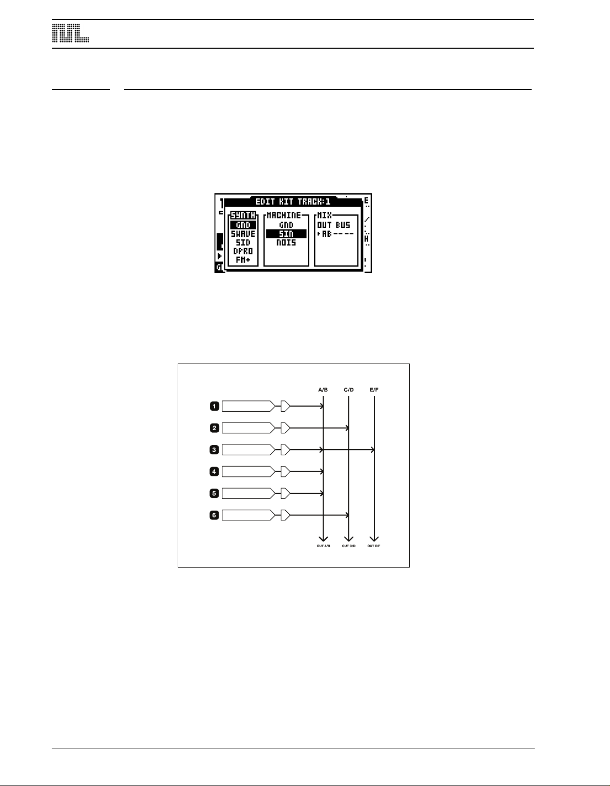
MONOMACHINE ROUTING
4:/5)&4*4
4:/5)&4*4
4:/5)&4*4
4:/5)&4*4
4:/5)&4*4
4:/5)&4*4
5'95'95'95'95'95'9
.*9.*9.*9
MONOMACHINE ROUTING
The Monomachine offers a flexible routing system for addressing the audio outputs, as well
as using the audio inputs and routing between the synthesis and FX machines.
Most of the routing is controlled from the EDIT KIT window. Please check section
“ASSIGNING A MACHINE TO A TRACK”, on page 21 for information on how to find, open
and manoeuvre it.
THE MONOMACHINE MIXER
The OUT BUS parameter in the MIX tab is available for all machines. It selects which mix
busses the track will be sent to. The Monomachine offers three stereo mix buses named
AB, CD and EF. At the end of the mix bus the sound is by default sent to the audio output
pairs AB CD and EF.
80
If no FX Machines are used the mix bus selection simply selects the audio stereo output(s)
the track will be sent to. In the example above the synthesis tracks are sent to different
audio outputs, so further external audio processing is possible for the individual tracks. The
third track is sent to two outputs.
THE FX MACHINES
The FX Machines works a little bit different compared to the synthesis machines as they do
not generate any sound themselves. They need to be fed sound in order to work as supposed. The sound sources can either be the audio inputs, the sound of the previous track
or the audio coming from one of the mix buses.
Page 89
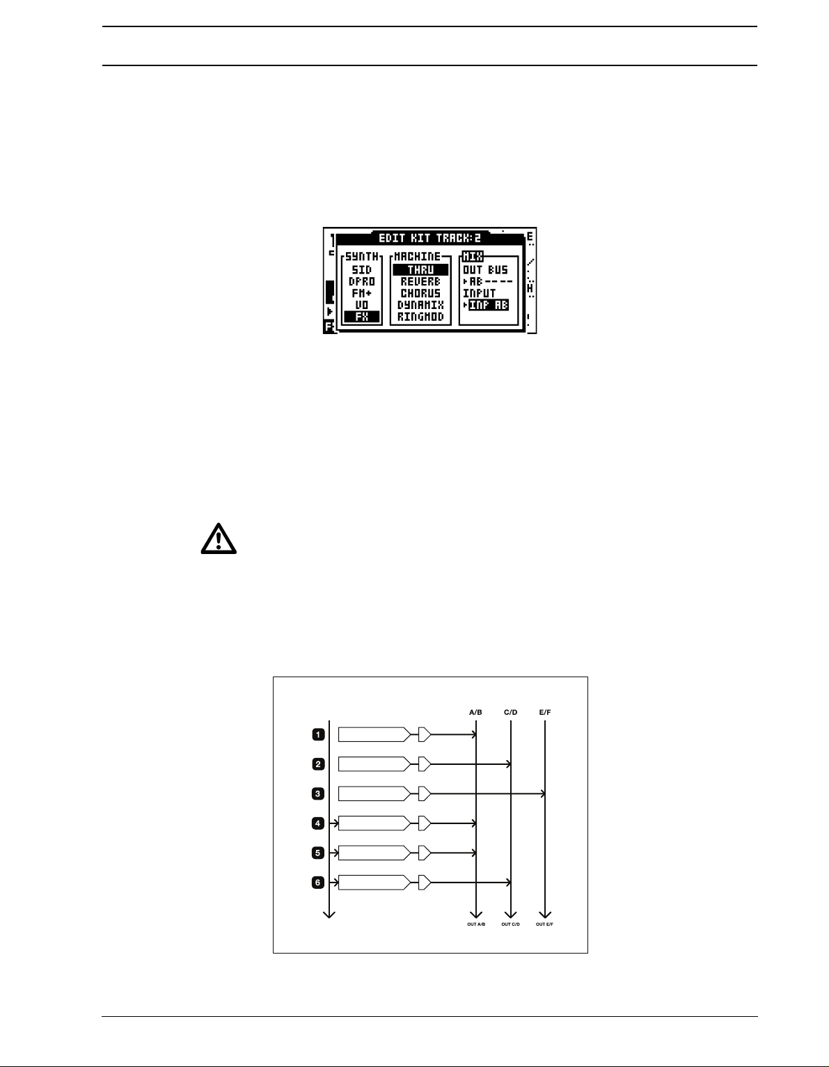
MONOMACHINE ROUTING
4:/5)&4*4
4:/5)&4*4
4:/5)&4*4
'9*/1"#
'9*/1"
'9*/1#
5'95'95'95'95'95'9
*/165
"#
.*9.*9.*9
USING THE AUDIO INPUTS
Audio can be routed from the external inputs and be effected with both track effects and FX
machines. The audio inputs are available to the FX machines found in the Monosynth
named “FX”. Follow the steps below to assign
1. Press the [
KIT/SONG SETUP] key to open the KIT window. Move the focus to the EDIT
icon and press [ENTER/YES] key.
2. Scroll down to the FX machines. You will find this selection at the end of the list.
3. The THRU machine is a good starting point as it will just let the audio from the source
elected through without other processing but a signal amplifier and of course the track
s
effects. Assign the THRU machine to a track.
4. Use the [LEFT] and [RIGHT] keys go to the INPUT parameter field and select INP A,
INP B or INP AB. Please note that the INPUT parameter field does not appear until an
FX machine is selected with [ENTER/YES].
• INP A - Monophonic audio is used from Audio Input A.
• INP B - Monophonic audio is used from Audio Input B.
• INP AB - Stereo audio is used from Audio Input A and B.
• Before any sound is heard from the audio input you need to trig the track so the
machine is activated. Play any note for the track; the pitch of the key is ignored by
the THRU machine.
In the routing example below synthesis machines are mixed with FX machines with input
taken from the audio inputs. The audio inputs are only printed explicitly in this example.
81
Page 90

MONOMACHINE ROUTING
4:/5)&4*4
4:/5)&4*4
'9/&*()#063
4:/5)&4*4
4:/5)&4*4
'9/&*()#063
5'95'95'95'95'95'9
.*9.*9.*9
• All track effects, the LFO’s and the sequencer are still at your hands when using
the audio inputs! Set up six tracks with various track effect settings, LFO settings
and use the sequencer on top of this, and you have a unique and powerful effects
processor.
• The output of the tracks always pass through the track effects, of which the ampli-
fier envelope is part. If you want the audio to pass through without decaying you
need to set DEC and REL to their maximum levels (127) and retrig the machine.
NEIGHBOUR ROUTING
The FX machines can also take their inputs from internal synthesis sound of the Monomachine. One of the modes for this is the NEIBOR mode. To use this mode, set track number
two or higher to use an FX machine, and set INPUT to NEIBOR.
In NEIBOR mode, the output of the previous track is used directly, and fed into the input of
the FX machine of the current track. Only the input of one track is used for the input, but
NEIBOR FX machines can be chained.
In the example above all audio outputs are set to the main AB mix bus. Track 2 and 6 is
routed to FX machines set to NEIBOR mode, and the input is taken directly from the previous track. All outputs are turned off for track 2 and 5.
82
• Use the neighbour FX to get access to an additional track effect! If you rather want
the distortion to be applied after all other effects, you can assign a THRU FX
Page 91

MONOMACHINE ROUTING
4:/5)&4*4
4:/5)&4*4
4:/5)&4*4
4:/5)&4*4
4:/5)&4*4
'9#64"#
5'95'95'95'95'95'9
.*9.*9.*9
machine in NEIBOR mode to the track after, and all the track effects of the second
track will be applied after the first one. Just remember to turn off the outputs of
the first track.
• NEIBOR mode is good for quick FX routing, when no more than one track need to
e fed into the FX.
b
MIX BUS ROUTING
For applying an effect to two or more mixed tracks you need to use the mix buses as input
for the FX machine. To use this mode, set track number two or higher to use an FX
machine, and set INPUT to “BUS XX”, where XX is the mix bus AB, CD or EF.
When the output of a track in the Monomachine is set to AB, CD or EF, it is fed to one of the
three mix buses, which by default ends in the audio outputs with the same names. The
tracks are mixed in the same order as their index, with track 1 first.
The contents of the mix bus can be used as input for the FX machines. If the same bus is
used for input and output, the FX is applied as an insert effect. If another bus is used to output the FX output is mixed into the track normally, just like synthesis machines.
In the example above all tracks but the third is assigned to the AB mix bus. Track 5 is a FX
machine, with INPUT and OUTPUT set to MIX AB. As the output is the same as the input
the FX is applied as an insert effect. What will happen is that track 1, 2 and 4 will be mixed
and effected by track 5. The output of the effect will then be mixed with track 6 and sent to
the AB outputs. Track 3 is sent by itself to the EF outputs, non-effected.
83
Page 92

MONOMACHINE ROUTING
4:/5)&4*4
4:/5)&4*4
4:/5)&4*4
4:/5)&4*4
'9#64"#
5'95'95'95'95'9
'9#64$%
5'9
.*9.*9.*9
In the example above the two first tracks are sent on the AB bus, and are thus effected by
the FX machine on track 3. Track 4 and 5 are sent to the CD mix bus. Track 6 is an FX
machine with input taken from the CD Mix bus, which now contains the mixed signal of
track 4 and 5. The output of the FX machine on track 6 is set to bus AB with differs from the
input CD. Therefore the effected track 4 and 5 is effected and sent to mix bus AB, where
they are mixed with the Track 1 and 2 effected by track 3.
ROUTING MODE AB=MIX
By default the mix buses are sent to the audio outputs with the same names. If you are
using only the main AB stereo outputs, or the headphones which carry the same signal,
you will not hear what is sent to the CD and EF outputs. By setting the global routing (see
section “GLOBAL ROUTING”, on page 87) to “3xSTEREO + AB=MIX” the CD and EF
buses will be added to the stereo main AB/headphone outputs.
ROUTING MODE 6xMONO
By setting the global routing (see section “GLOBAL ROUTING”, on page 87) to “6xMONO”,
the AB, CD and EF mix buses will not be sent to the audio outputs. Instead, each of the
stereo outputs of the six Monomachine tracks are mixed to mono, and fed to an individual
output. The mix buses can still be used, but the final output of them will not be sent to the
AB, CD and EF outputs.
Using this mode makes it possible to get the output of each of the Monomachine tracks
sent to an individual output, but the stereo effects and panning are lost.
84
Page 93

MONOMACHINE ROUTING
4:/5)&4*4
4:/5)&4*4
'9/&*()#063
4:/5)&4*4
4:/5)&4*4
'9/&*()#063
5'95'95'95'95'95'9
065'
065&
065%
065$
065#
065"
.*9.*9.*9
The example above visualises how a global routing configuration of 6xMONO configures
the outputs.
• Like all machines, the FX machines need to be trigged before they make any
sound. The track effects are active as always, so if you want the sound to go
through without decaying you need to set the DEC and REL parameters to their
maximum values (127).
85
Page 94

GLOBAL SETTINGS
GLOBAL SETTINGS
The Monomachine offers 8 individual slots for storing global settings. The multiple global
slots are useful for using the unit in different settings. You can have one setup for studio
use and another for the live set, or maybe different setups for different parts of the live set.
The items listed below are available in the GLOBAL menu.
• Turbo menu
• Master tune
• Audio routing options
• MIDI channel setup
• MIDI control settings
• Multi map editor
• Mechanical settings (MKII units only)
• Keyboard velocity response (SFX-6 units only)
• SYSEX send/receive
• DigiPRO waveform manager
• MIDI sequencer settings
1. Press [
2. Use the [ARROW]
[ENTER/YES] to select it. If it was already selected you have now also entered the Glo-
bal menu for the slot. If not, press [ENTER/YES] one more time to enter it.
FUNCTION] and then [PATTERN/SONG] to open the Global slot selection menu.
keys for navigating to the Global slot you wish to use, and press
TURBO MENU
The TURBO menu, only available in OS 1.22 and higher, allows you to use the Turbo protocol when connecting the Monomachine to other units that have the Turbo protocol implemented. This will speed up MIDI transfer times considerably, which is handy if you for
example want to transfer sysex data or waveforms to another Monomachine.
86
Page 95

GLOBAL SETTINGS
1. Connect the MIDI OUT of your Monomachine to the MIDI IN of the other unit and the
IDI IN of your Monomachine to the MIDI OUT of the other unit.
M
2. Press [FUNCTION] + [KIT/SONG] to open up the GLOBAL menu. Use the [ARROW]
keys to select TURBO. Press [ENTER/YES].
3. CURRENT SPEED shows the current multiplier of the MIDI transfer rate. When not con-
ected to a device using Turbo protocol compatible software, the speed will therefore be
n
x1.0. Select which NEGOTIATE speed you want use. The Monomachine defaults to x10,
but this value can be lowered should it be needed. Press the [ENTER/YES] button to
start to negotiate. The CURRENT SPEED value will display the change of the MIDI
transfer rate.
• If you link two Monomachines together where one of them is a MKI model, you
might not be able to get a CURRENT SPEED value exceeding 6.7x.
AUDIO
Here you set the master tune as well as the routing.
MASTER TUNE
The global master tune can be set in this menu.
1. Select the AUDIO in the GLOBAL menu. Then select MASTER TUNE using the
ARROW] keys and press [ENTER/YES].
[
Use [UP]/[DOWN] keys to set the integer part, and [RIGHT]/[LEFT] keys to set the fraction. The default value is 440.0 HZ.
GLOBAL ROUTING
In this menu one of three audio routing selections can be set.
87
Page 96
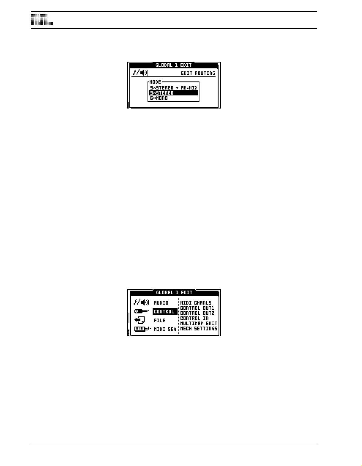
GLOBAL SETTINGS
1. Select the AUDIO in the GLOBAL menu. Then select ROUTING using the [ARROW]
eys and press [ENTER/YES].
k
Use [UP] and [DOWN] keys to move the focus, and confirm with [ENTER/YES].
3xSTEREO is the default configuration, where the three internal stereo mix buses AB, CD
and EF are sent to the audio outputs A/B, C/D and E/F.
3xSTEREO + AB=MIX, has the same function as mode 3xSTEREO described above, but
the CD and EF buses are mixed also to the A/B outputs, for users only using the A/B main
stereo outputs, or headphones.
6xMONO mixes the stereo output of each of the six Monomachine tracks to mono. The
tracks are then sent directly to each of the audio outputs. Track 1 is sent to output A, Track
2 to output B and so on.
Please see section “MONOMACHINE ROUTING”, on page 80 for detailed information on
the Monomachine routing possibilities.
CONTROL
The Monomachine is designed to fit well into a MIDI environment. It is well equipped for
ontrolling other units using the MIDI sequencer, the MIDI real-time messages (Timing
c
clock, Start, Stop) and Song Pointer Position. It is also ready for a large number of control
methods to fit in a wide range of environments. The CONTROL menu is also where you set
the resolution of the encoders and the keyboard velocity response of the SFX-6 keyboard.
MIDI CHANNELS
Here the MIDI channel setup of the Monomachine is found.
Select CONTROL in the GLOBAL menu. Then select MIDI CHANLS using the [ARROW]
keys and press [ENTER/YES].
88
Page 97

GLOBAL SETTINGS
Navigate between the parameters using the [UP] and [DOWN] keys. Change the parameter values using [LEFT] and [RIGHT].
By default the Monomachine responds to 9 MIDI channels. The first six channels directly
control each of the six internal monomachine tracks and are called the Individual Track
Channels. The MULTI TRIG, MULTI MAP and AUTO TRACK channels follow having specialised functions controlling the Monomachine.
BASE CHANNEL (base channel) is the default MIDI channel. Changing this can affect the
other channel settings as well.
CHANNEL SPAN (channel span) determines the number of MIDI channels used for the
individual track channels. The individual track channels are mainly useful if you are using
the Monomachine as a sound module. If you use the Monomachine in pattern, song, multi
trig or multi map mode, and you do not have the MIDI-channels to spare, you can disable
the individual track channels by reducing CHANNEL SPAN to zero.
MULTI TRIG CH (multi trig channel) directly controls the multi trig monophonic super-synth
functionality of the Monomachine. Please see section “MULTI TRIG”, on page 40 for more
information. Output data on this channel can only be generated from the keyboard of the
SFX-6 when MULTI TRIG Mode is selected.
MULTI MAP CH (multi map channel) controls the multi map functionality as described in
section “MULTI TRIG”, on page 40. Output data on this channel can only be generated
from the keyboard of the SFX-6 when MULTI MAP Mode is selected.
AUTO TRACK CH (auto track channel) is a control channel that follow the track selected
as active on the Monomachine interface. It is very useful for the SFX-60MKII table-top
module, as an external MIDI-keyboard assigned to this channel can be used for the functionality of the keyboard of the SFX-6. It saves the work of switching the channel on the
external keyboard when changing track focus of the SFX-60MKII. No output data is generated for the auto track channel.
MORE ON THE MONOMACHINE MIDI FUNCTIONALITY
Some MIDI commands are accepted on all active channels:
• NRPN data is accepted to control the individual internal tracks
• PROGRAM CHANGE can be used for changing pattern
T
he NRPN interface doubles with the normal CTRL CHANGE interface of the Individual
Track Channels, and provide the same functionality. It is only accepted, never transmitted.
See Appendix B for full MIDI specifications of the NRPN interface.
89
Page 98
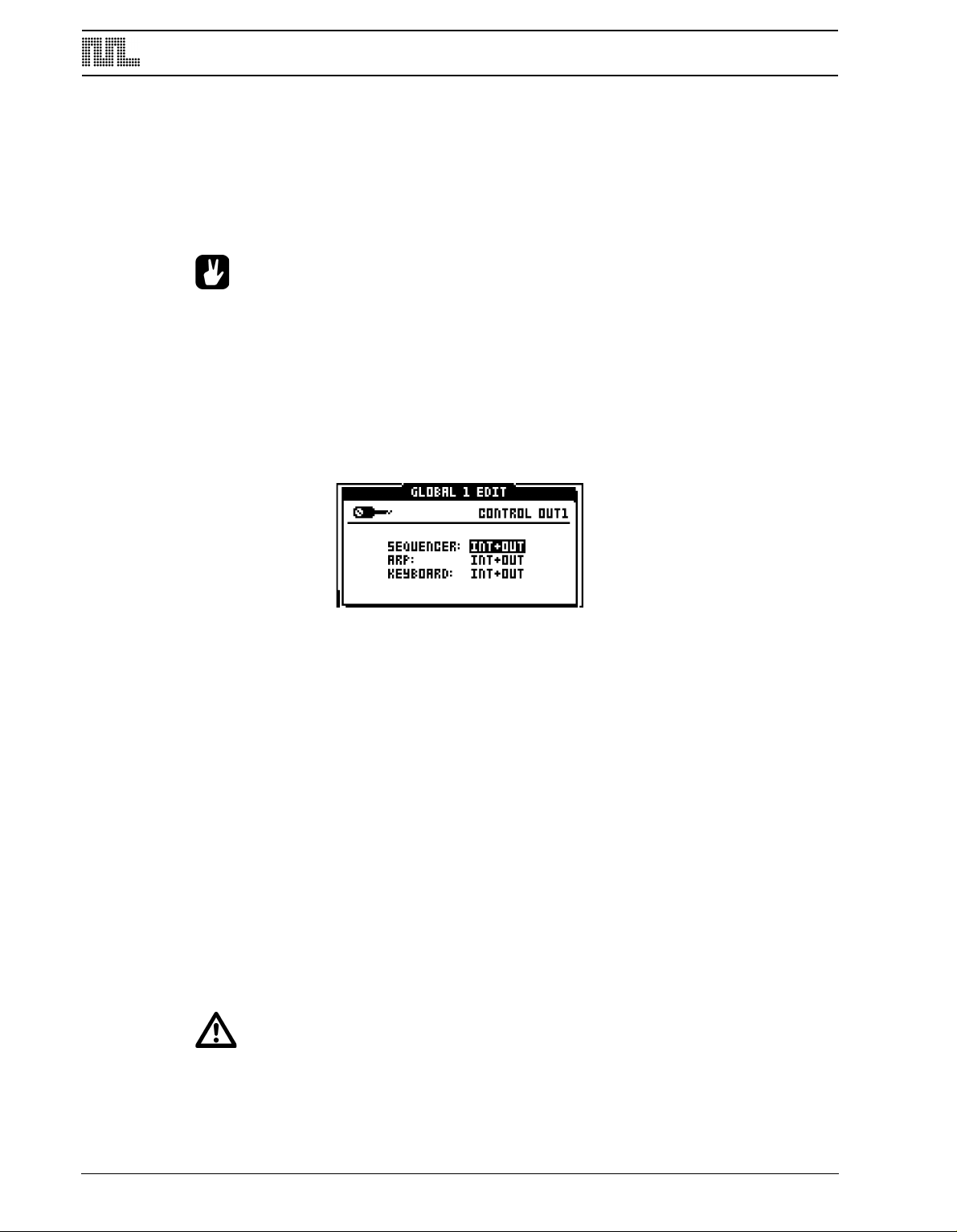
GLOBAL SETTINGS
PROGRAM CHANGE can be disabled for MIDI input and output. See section “CONTROL
OUT2”, on page 91 for more information.
The Monomachine SFX-6 joystick sends pitch-bend for right and left directions, CTRL
CHANGE 1 (mod wheel) for the upward direction and CTRL CHANGE 2 (breath control) for
the downward direction. The same messages are accepted by the SFX-60MKII as joystick
control.
• If the individual track channel is disabled you can still control the individual track
parameters using the NRPN interface.
CONTROL OUT1
This menu contains parameters that control how the Monomachine sends MIDI note and
control data.
1. Select the CONTROL in the GLOBAL menu. Then select CONTROL OUT1 using the
[ARROW] keys and press [ENTER/YES].
Navigate between the parameters using the [UP] and [DOWN] keys. Change the parameter values using [LEFT] and [RIGHT].
SEQUENCER (sequencer) controls whether MIDI data of the sequencer should be sent to
the internal synthesizer tracks, MIDI OUT or both.
ARP (arpeggiator) controls whether MIDI data of the arpeggiator should be sent to the
internal synthesizer tracks, MIDI OUT or both.
KEYBOARD controls whether MIDI data of the keyboard and joystick (SFX-6 only) should
be sent to the internal synthesizer tracks, MIDI OUT or both. The keyboard on the SFX-60/
SFX-60 MKII is represented by the [TRIG] buttons when not in the GRID RECORDING or
LIVE RECORDING modes.
The available selections for all the parameters are:
• INT - O
nly internal control, no external MIDI data will be sent.
• OUT - No internal control, only external MIDI data will be sent.
• INT+OUT - Internal control, and MIDI data will be sent.
• Parameter locks of the internal tracks are not transmitted over MIDI, because the
data transfer rate of the MIDI standard is too low for delivering large number of
control data in time.
90
Page 99
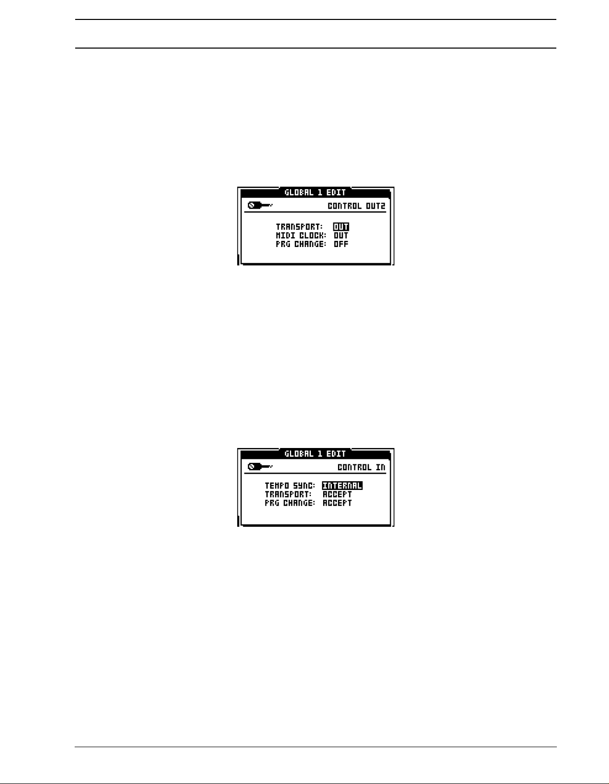
GLOBAL SETTINGS
• Note that if internal control is shut off the Monomachine might appear non-func-
ional if MIDI data is not echoed back from an external sequencer.
t
CONTROL OUT2
Here parameters dealing with how the Monomachine handles outgoing MIDI sequencer
control messages are found.
1. Select the CONTROL in the GLOBAL menu. Then select CONTROL OUT2 using the
[ARROW] keys and press [ENTER/YES].
TRANSPORT (transport) controls whether MIDI Start, Stop and Song Pointer Position are
sent.
MIDI CLOCK (MIDI clock) controls whether the Monomachine transmits MIDI clock.
PRG CHANGE (program change) controls whether MIDI PRG CHANGE is sent for each
pattern change.
CONTROL IN
In this menu it is defined how the Monomachine should react to incoming MIDI.
1. Select the CONTROL in the GLOBAL menu. Then select CONTROL IN using the
ARROW] keys and press [ENTER/YES].
[
TEMPO SYNC (tempo sync) defines how the Monomachine should react to incoming MIDI
clock. When this parameter is set to EXTERNAL, the Monomachine tempo will be slaved to
incoming MIDI time clock. The precision of the timing is limited to the precision of the unit
transmitting the MIDI clock signal. When locked to external clock the BPM indicator on the
main screen shows “EXT”. If no clock signal is received, the Monomachine will fall back to
its internal tempo after a few seconds. When a clock signal is received again the Monomachine will be synced to the external tempo.
TRANSPORT (transport) controls if the Monomachine should respond to MIDI Start, Stop
and Song Pointer Position.
When the Transport parameter is set to ACCEPT, MIDI start, stop and song pointer position
messages are recognised.
When the TRANSPORT parameter is set to IGNORE, MIDI start, stop and song pointer
positions are ignored.
91
Page 100

GLOBAL SETTINGS
PRG CHANGE (program change) controls whether PRG CHANGE received changes pat-
tern of the Monomachine.
• The Monomachine can transmit a high precision MIDI clock. It is often a good idea
to use the Monomachine as master instead of slave, as the timing of other MIDI
equipment including many setups with well-known Windows and Mac sequencers
is not always reliable.
MULTI MAP EDIT
The MULTI MAP EDIT menu provides a fully configurable keymap for trigging patterns.
1. Select the CONTROL in the GLOBAL menu. Then select MULTIMAP EDIT using the
ARROW] keys and press [ENTER/YES].
[
Each row represents one range of the keyboard named keymap range where one selected
pattern will be trigged according to the settings on the row.
Navigate in the keymap using the [ARROW] keys. Adjust the settings using the LEVEL
knob.
RANGE (range) is a column where the upper and lower key range limits for the keymap
range is controlled. Only the upper range limit can be set. The lower range limit is set one
key higher than the previous keymap range upper limit. Adjusting the upper range limit will
update the lower range limit for the next range limit. Keymap ranges can be inserted using
[FUNCTION] + [DOWN] and deleted using [FUNCTION] + [UP]. When inserting new keymap ranges there need to be room in the current keymap range. If the range is only one
note no new range can be inserted at that position.
PAT (pattern) is the column where the patterns which will be trigged for the keymap range
are set. The first pattern, called CUR, means the current pattern. If CUR is selected the
keymap range settings will be applied to the pattern currently selected when the range is
played.
OFS LEN (offset and length) is where the playback start and range of a pattern can be
adjusted. The OFS column can set a start point for the pattern to begin to play and loop.
The LEN column sets a maximum length of the pattern. Note; the offset need to be set for
the LEN parameter to be accessible.
TRN (transpose) allows the pattern assigned to the keymap range to be transposed.
92
TIM (timing) allows the pattern start to be delayed for the pattern assigned to the keymap
range. It has the same function as the timing parameter found in the MULTI TRIG menu
(see “MULTI TRIG” on page 40).
 Loading...