

Page 1
Operating Manual
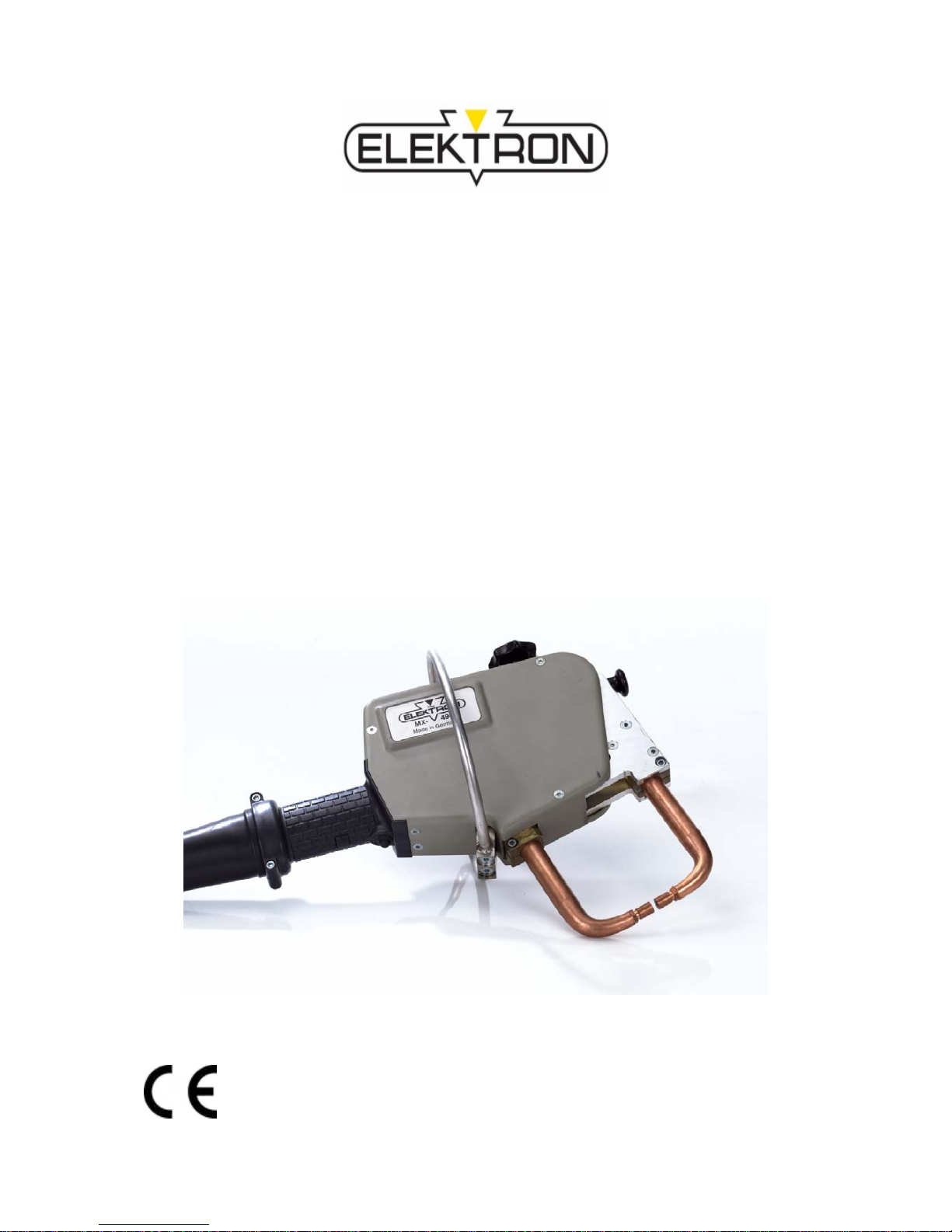
MULTISPOT
MX 3900 and MX 4900
Spot welding pliers for resistance welder
Item no. 327 670 Be sure you have read and understood
Revision: 2.0 – Translation this operating manual before you carry
Version: 18
nd
, March 2010 out any works on and/or with this
e
quip
ment.
Page 2

2
©
ELEKTRON Bremen GmbH
Hinterm Sielhof 22
28277 Bremen
Germany
Phone: +49 (0) 421 – 54 90 6 – 0
Fax: +49 (0) 421 – 54 90 6 – 19
E-Mail: vertrieb@elektron-bremen.de
Web: www.elektron-bremen.de
Release:
ELEKTRON Bremen GmbH
Page 3

MX 3900 / MX 4900
3
Inhaltsverzeichnis
1. GENERAL INFORMATION............................................................................................................ 4
1.1 Information concerning the operating manual .................................................................... 4
1.2 Symbols .............................................................................................................................. 4
1.3 Warning notes for operating resistance welder .................................................................. 5
1.4 Disclaimer ........................................................................................................................... 5
1.5 Copyright............................................................................................................................. 6
1.6 Warranty and guarantee ..................................................................................................... 6
1.7 Customer service ................................................................................................................6
2. HEALTH AND SAFETY.................................................................................................................7
2.1 Responsibilities of the operating company ......................................................................... 7
2.2 Personal protective equipment (PPE)................................................................................. 7
2.3 Particular dangers............................................................................................................... 8
2.4 Correct behaviour in accidents and dangerous situations................................................ 10
2.5 Symbols the operating company must install in the immediate vicinity of the equipment 10
3. TRANSPORT, PACKAGING, STORAGE ................................................................................... 11
3.1 Safety during transport...................................................................................................... 11
3.2 Symbols on packaging...................................................................................................... 11
3.3 Acceptance after shipping................................................................................................. 11
4. DESIGN AND FUNCTIONALITY.................................................................................................12
4.1 Overview spot welding pliers ............................................................................................ 12
5. OPERATION................................................................................................................................. 13
5.1 Installation and preparation of spot welding pliers............................................................ 13
5.1.1 Mounting ring bar.................................................................................................. 13
5.1.2 Connecting the pliers............................................................................................ 14
5.1.3 Preparation of the spot welding pliers .................................................................. 15
5.2 Preparing the welding spot ............................................................................................... 17
5.3 Operating the spot welding pliers...................................................................................... 18
5.4 Welding set up, for example at the MI-100control ............................................................ 19
6. SPECIFICATIONS........................................................................................................................ 20
6.1 Pliers MX 3900..................................................................................................................20
6.2 Pliers MX 4900..................................................................................................................20
6.3 Power requirement............................................................................................................ 20
6.4 Working conditions............................................................................................................ 21
6.5 Exposure limit values ........................................................................................................ 21
6.6 Type plates........................................................................................................................ 21
INDEX.................................................................................................................................................... 22
Page 4

MX 3900 / MX 4900
General information
4
1. General Information
1.1 Information concerning the operating manual
This operating manual provides important directions for handling the device. Compliance with
any and all information contained herein concerning health, safety and safe behaviour and procedures is a prerequisite for safe work.
Shall apply in addition: any and all local accident prevention regulations, any and all general
safety regulations that may apply to the scope of application of this equipment The manual is an
essential part of this product and must be stored ready at hand not far from the equipment so
that people can use it at any time without any problems..
1.2 Symbols
Safety information
This manual uses symbols to highlight important safety information. In addition, there is always
a signal word heading the information indicating the severity of the danger or hazard that may
be encountered.
Be sure to comply with any and all safety information. Proceed with care and circumspection.
Prevent accidents and damage to people and property.
DANGER
… indicates a situation that is imminently dangerous and will entail the death of people
and severe injuries unless it is properly avoided and prevented.
WARNING
... indicates a situation that may become dangerous and may entail the death of people
and severe injuries unless it is properly avoided and prevented.
CAUTION
... indicates a situation that may become dangerous and may entail medium and small
injuries unless it is properly avoided and prevented.
CAUTION
… indicates a situation that may become critical and may entail damage to property
unless properly avoided and prevented.
Electricity
Electricity constitutes a danger to life and limb.
Electromagnetic fields
Electromagnetic fields pose a potentially fatal hazard to people with pacemakers or
other magnetisable implants.
Moving machine parts
There is a danger of injury as long as the device moves.
Harmful substances
Danger due to poisonous, at least harmful vapours.
Crushing hazard
There is a danger of injury as long as the device is operating.
Hot surfaces
Danger of burning due to hot surfaces.
Slip hazard
Slip hazard due to water coming out.
Stumbling hazard
Danger of injury due to stumbling and falling.
Page 5

MX 3900 / MX 4900
General information
5
Tipps, tricks and recommendations
1.3 Warning notes for operating resistance welder
Caution!
When operating resistance welding devices the accident prevention regulation
BGV B11 (electromagnetic fields) and the BG-regulations BGR B11 have to be followed. The power supply unit and supply lines of welding gun and spot welding tongs
generate a strong electromagnetic field during operation. Electromagnetic fields may
cause irritations of sense organs, nerves- and muscle cells as well as mal functions of
body supporting devices (deaf aid, pacemaker etc.) and of electronic devices and data
memories.
Cable pliers:
At a distance of 15 cm perpendicular to the frame enclosed by the electrodes the exposure limit values of the EU-Directive 2004/40/EG and the identical basic values corresponding to the accident prevention regulation BGV B11 will most probably be adhered
to. At the welding cable of spot welding tongs the exposure limit values of the EUDirective 2004/40/EG and the identical basic values of the accident prevention regulation BGV B11 will be already adhered to at distances from 7 cm for sure.
Further notes for operating with magnetic fields:
Magnetic fields occur during the welding process only (time of current flow).
The head must not be in the vicinity of the frame enclosed by the electrodes or the
electrodes themselve during the welding process.
The welding cables must not be guided along or in the vicinity of head and spines.
1.4 Disclaimer
Any and all information contained in this operating manual has been written on the basis of pertinent standards and regulations, the state of the art, and the long-standing insights and experience of our staff.
The manufacturer cannot be made liable for damage due to:
non-compliance with this operating manual
non-compliance with the purpose and intent of this equipment
deployment of unskilled personnel
unauthorised constructional changes, alterations etc.
unauthorised changes, modifications etc. to design and engineering etc.
use of unauthorised spare and wear parts
The scope of the delivery you actually receive may deviate from explanations and/or representations in this manual - if and when you ordered special options, your equipment is a special design and/or technical progress facilitates improvements.
i
NOTE!
... highlights information that may be helpful to maintain efficient and troublefree
operation.
Page 6

MX 3900 / MX 4900
General information
6
1.5 Copyright
This operating manual is protected by copyright. It may be used for internal purposes, exclusively. The manual and/or its contents may not be relinquished to third parties and/or communicated, processed, used and/or reproduced in any way or form whatsoever (not even in excerpts
and/or for internal purposes) without the prior written consent of the manufacturer.
Contravention shall entail damage claims.
1.6 Warranty and guarantee
The guarantee conditions are a separate document within the sales records.
1.7 Customer service
Our customer service will be happy to provide technical support.
For contact information see our homepage or see page 2 of this manual.
Page 7

MX 3900 / MX 4900
Health and safety
7
2. Health and safety
This section contains an overview of the most important health and safety at work aspects in
order to protect employees and to guarantee safe and troublefree operation.
Non-compliance with any and all of the information, safe behaviour and procedures etc. contained herein may entail severe health and safety risks.
2.1 Responsibilities of the operating company
This equipment has been designed for professional use. The owner/operator or operating
company therefore is subject to any and all legal obligations concerning health and safety at
work.
That means, in addition to this operating manual, any and all accident prevention, health and
safety at work and environmental regulations pertaining to this equipment's scope of application shall apply as well. This means in particular:
The operating company must be informed about any and all pertinent health and safety at
work regulations and must carry out a risk assessment in order to determine additional
hazards existing under the specific conditions in the specific work environment at the
place of operation. Any and all findings from such a risk assessment must then be used
to draw up additional operating instructions for the operation of this equipment.
During the entire lifetime of this equipment, the operating company must check in regular
intervals whether such additional operating instructions are still up to date and must update them when necessary.
The operating company must unambiguously determine and communicate responsibili-
ties concerning the installation, operation, maintenance and cleaning of this equipment.
The operating company must make sure that any person handling this equipment has
read and understood this operating manual. Operating personnel, in addition, must be
trained in regular intervals and must be informed about the dangers existing in connection
with this equipment. (For a draft of a training report form, see "Appendix”
The operating company is responsible that the equipment is in proper working order at all
times. Therefore:
The operating company must make sure that any and all maintenance jobs described in
this manual are really carried out.
The operating company must have any and all safety labels, markings etc. on the equip-
ment checked for integrity and readability in regular intervals.
2.2 Personal protective equipment (PPE)
Wearing PPE during work is essential to minimise health and safety risks.
Be sure to be always wearing the appropriate PPE for the job at hand.
Be sure to take note of and comply with warning signs concerning PPE that may be in-
stalled at the workplace.
Wear principally
At all works wear principally:
Non-inflammable safety clothing
is a tight-fitting sort of special clothing that is not inflammable, covers arms
and legs completely and tears easily (instead of getting pulled in). Its main
purpose is to protect against burns.
Safety shoes
protect the wearer's feet against falling objects, slippery surfaces and being
run over by vehicles.
Page 8
MX 3900 / MX 4900
Health and safety
8
Wear for special work
For special work special protective equipment is necessary. It will be indicated in the certain
chapters. Following special equipment will be explained:
Face screen
protects the face and eyes against splashes, flying sparks and other hot
particles.
Ear protection
protects against hearing damage.
Welder's gloves
protect the hands against splashes, flying sparks and other hot particles,
and prevent contact with hot surfaces. Never use wet welder's gloves.
2.3 Particular dangers
Electricity
DANGER ! Electricity constitutes a danger to life and limb.
Touching live components can result in a fatal electrical shock. Therefore:
As soon as you notice any damage to insulation, disconnect the power
supply and have the damage repaired.
Before any and all electrical works: disconnect power, earth and short.
Check whether equipment is really dead.
Keep live components away from liquids and humidity. They may cause
short circuits.
Protect cables against running over, contact with oils, aggressive sub-
stances, tools, pointed and/or hot objects.
When pulling from a socket: Never pull on the cable. Pull on the plug.
Do not use the cable to trail or drag equipment over the floor. Always
grab equipment by the handles provided for that purpose.
Use strain relief clamps to protect cables.
Make sure protective ground conductors have been connected
properly.
Electromagnetic fields
DANGER! Electromagnetic fields pose a potentially fatal hazard to
people with pacemakers or other magnetisable implants.
Electromagnetic fields affect the functionality of pacemakers and other magnetisable implants. Electromagnetic fields can irritate human sense organs,
nerve and muscle cells. Therefore:
Persons with pacemakers or other magnetisable implants must not ap-
proach the work area.
Be sure to put up suitable warning signs.
Be sure to put warning signs on access ways and doors leading to the
work area.
Do not guide welding cables along people's heads or spines. (To comply
safely with permissible exposure limits, keep distances ≥ 20 cm. Keep a
distance of at least 1 cm between cable assemblies and people's heads /
spines.)
Electromagnetic fields – hazard to magnetisable objects
Magnetisable data carriers and similar objects that may suffer from mag-
netism must not be brought close to this equipment.
Page 9

MX 3900 / MX 4900
Health and safety
9
Splashes and flying sparks
WARNING ! Splashes and flying sparks constitute a danger of fire and
explosion. Splashes and flying sparks pose a risk of injuries.
Welding generates sparks and -hot spatter. They can ignite combustible materials and generate explosions. Contact with body parts may entail injuries.
Therefore:
Before you tackle any welding jobs, make sure there are no combustible
and/or explosive materials in the work area.
Do not carry out welding jobs in the vicinity of pressure vessels, tanks, oil
barrels, paint cans and/or in a work area with an explosive atmosphere.
Have fire extinguishing gear ready at hand.
Make sure access and escape routes are not blocked.
During any and all welding jobs: be sure to be wearing a face screen,
non-inflammable safety clothing and welder's gloves.
Do not carry easily inflammable objects in your pockets (matches,
lighters etc.).
Hot surfaces
CAUTION ! Hot surfaces pose a risk of burns.
Electrodes may heat up to 80 degrees centigrade approx. Stock may have
up to 100 degrees right after welding. So there is an acute risk of burning
yourself. Therefore:
Never work without proper safety clothes and gloves near hot compo-
nents.
Let freshly welded parts cool down to ambient temperature before you
go on to work with them.
Vapours
WARNING ! Vapours may constitute a danger to your health.
Stock that has not been properly ground and cleaned before welding may
be contaminated with residues of glues, paints, undercoating products etc.
that may generate harmful or even toxic vapours during welding. Therefore:
Before you tackle any welding jobs, make sure the sheets you want to
weld have been properly ground and cleaned and are free of residues.
Be sure to be wearing a face screen. Respiratory equipment may be rec-
ommendable in case of doubt.
Page 10

MX 3900 / MX 4900
Health and safety
10
Stumbling hazards
WARNING ! Possibility of injuries due to stumbling and falling.
The work environment may pose stumbling risks. Stumbling and falling may
lead to severe injuries. Therefore:
Before you tackle any welding jobs, make sure the work area is tidy and
free of clutter and offers enough freedom to move.
Install cables and supply lines in such a way that they do not constitute a
stumbling trap.
When welding, assume a safe and stable working position.
2.4 Correct behaviour in accidents and dangerous situations
Preventive measures
Be prepared to confront accidents and fires.
Be sure to have first aid equipment (kits, blankets etc.) and fire extinguishers ready at
hand.
All personnel must know about accident signalling systems, first aid, rescue and escape
equipment.
Keep access ways for ambulances clear and open.
Measures to be taken in case of accidents
Actuate emergency stop.
Initiate first aid.
Evacuate people from danger zone.
Alert persons in charge.
Alert fire brigade and ambulance service.
Keep access ways for ambulances clear and open.
2.5 Symbols the operating company must install in the immediate vicinity of
the equipment
WARNING!
Danger of injuries due to unreadable symbols!
Over time signs and symbols on the device may get dirty or efface due to
other reasons. Therefoe:
All safety-, warnings-and operating directions at the device must always
be kept in a good and readable condition.
Renew at once damaged signs and symbols.
Regard operating instructions
Before using the signed device read the operating instructions.
Moving machine parts
Maintenance work at opened machines may be done only by skilled persons.
As long as the machine moves there is a danger of injury.
Electrical voltage
Only electricians may work in a room signed with this symbol.
Unauthorized persons may not enter the room or open the locker.
Page 11

MX 3900 / MX 4900
Transport, packaging, storage
11
3. Transport, packaging, storage
3.1 Safety during transport
Inexpert transport
CAUTION ! Improper transport may cause damage to property.
Improper transport may cause damage to property. Therefore:
When you unload packing units and move them across your premises, proceed
with care. Consider symbols and information on packaging.
Be sure to transport equipment as described hereinafter. ( See "3.5".)
3.2 Symbols on packaging
None.
3.3 Acceptance after shipping
Check packing units immediately after delivery. Check for integrity, missing pieces and damage.
If you detect any external shipping damage, proceed as follows:
Do not accept delivery. Or accept under reserve.
Report damage on carrier's shipping papers or delivery ticket.
Initiate complaint procedure.
NOTE!
Be sure to register a complaint as soon as a defect has been detected. Claims for
damages may be brought forward only within the deadlines set for complaints.
Page 12

MX 3900 / MX 4900
Design and functionality
12
4. Design and functionality
4.1 Overview spot welding pliers
Fig. 1: Spot welding pliers
1. Star knob
2. Electrode arm, movable, Ø 25 mm
3. Electrode caps
4. Electrode arm, stationarz, Ø 25 mm
5. Electrode arm receptacle
6. Momentary contact button
7. Welding cable
8. Ring bar
9. Adjusting and release button for movable electrode arm
10. Hexagon screw for fixing the electrodes
3
6
5
2
7
9
8
1 4
10
Page 13

MX 3900 / MX 4900
Operation
13
5. Operation
5.1 Installation and preparation of spot welding pliers
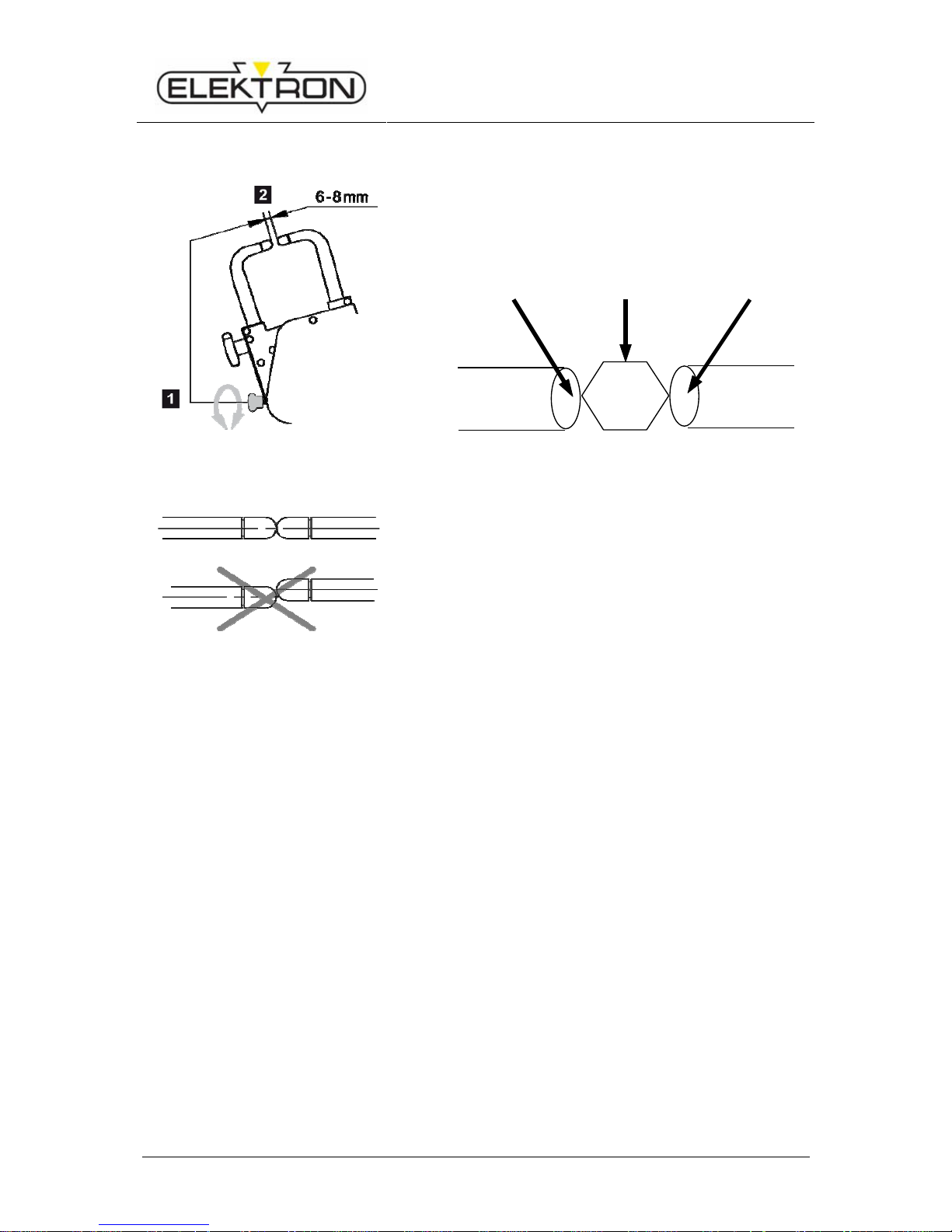
5.1.1 Mounting ring bar
1. Mounting ring bar
2. Put in screws with plastic sleeves (isolation)
3. Fix screws tight
4. Ring bar fixed at pliers
Fig. 2: Mounting ring bar
Page 14

MX 3900 / MX 4900
Operation
14
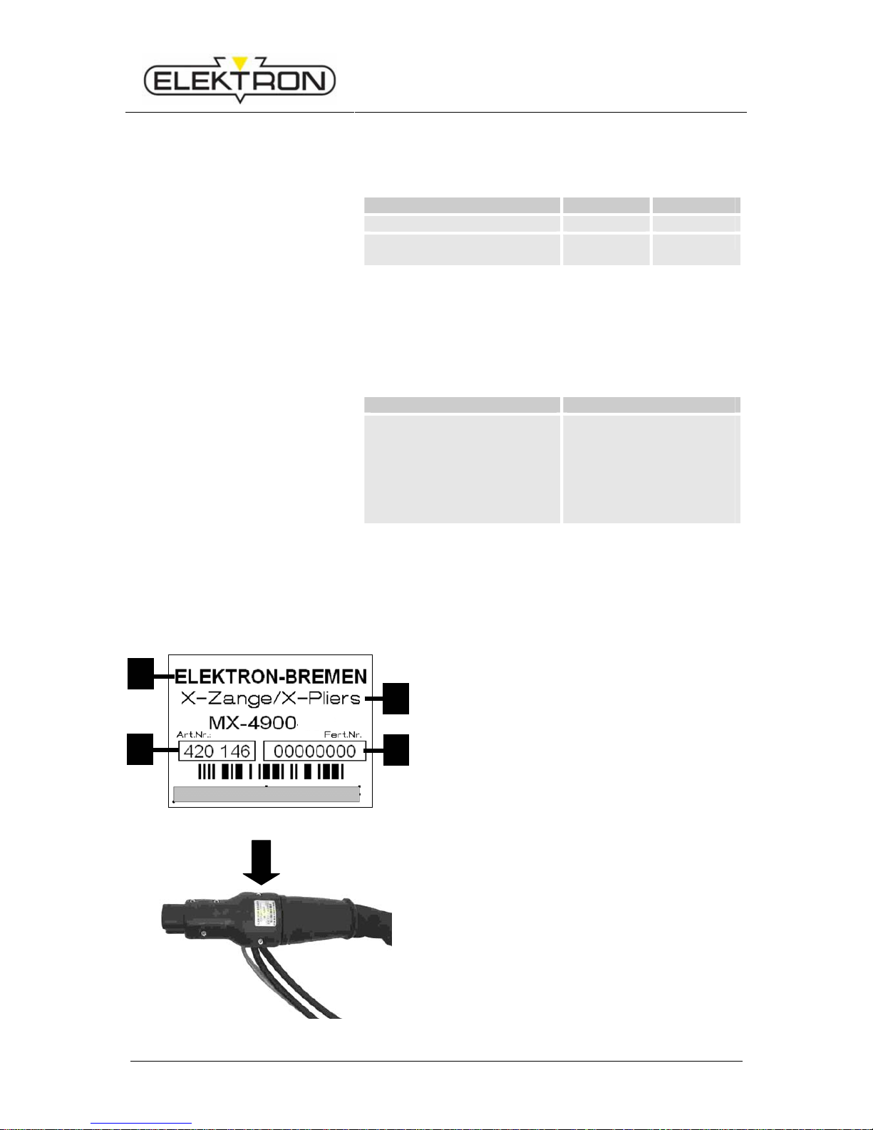
5.1.2 Connecting the pliers
2.
1.
Fig.3: Connecting the pliers
1. Push the main plug of the welding pliers into the main
socket of the equipment (Fig.3/1.).
2. Turn the retainer nut clockwise (Fig.3/2.) to lock the
connection. Important: Otherwise the copper plates in
the central connection can be damaged.!
Fig.4: Water cooling system for the pliers
3. Connect the water cooling system of the pliers.
Fig.5: Connecting sensors of the pliers
Applies only for the MX-4900:
4. Connect the sensors of the pliers.
Page 15
MX 3900 / MX 4900
Operation
15
5.1.3 Preparation of the spot welding pliers
Scald hazard
DANGER! Scalding may occur due to hot water coming out!
While pulling out the cooling water hoses hot water may come out.
Therefore:
– Wear gloves.
– Pull out water hoses carefully.
Slip hazard
DANGER! Slip hazard due to water coming out!
While pulling out the cooling water hoses water may come out.
Therefore:
– Remove water from the floor.
Device switches automatically to the right pliers symbol.
Insert electrode arm into electrode receptacle (s.0).
Click movable electrode arm into place.
Adjust distance of electrodes with the adjusting button at 6 to 8 mm (s. 5.1.3.4 )Fix
hexagon screws tight.
Check the distance of electrodes again after the first welds and adjust, if necessary.
WARNING
Unintentional startup of welder may constitute a hazard of injuries.
If the new tool is switched on during retooling, the weld current and/or unintentional
movements of the pliers may be actuated. There is a danger of pinching and
crushing.
Therefore:
Be sure to tool up first, and only then switch on the welder.
If retooling is unavoidable during the work, be sure to switch OFF before you
do anything.
CAUTION
Switch off cooling first before changing electrodes !
Page 16
MX 3900 / MX 4900
Operation
16
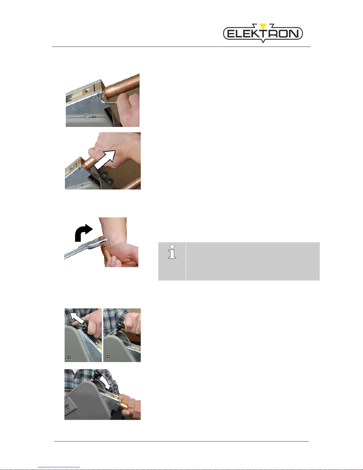
5.1.3.1 Exchanging electrode arms
Fig.6: Unbolting electrode arm
1. To unbolt the electrode arm, use the Allen key provided for that
purpose (Fig.6).
Fig.7: Removing the electrode arm.
2. Remove the electrode arm simply by pulling it out.
(Fig.7).
3. Insert the new electrode arm and bolt down.
5.1.3.2 Exchanging electrode caps
Fig.8: Exchanging electrode caps
1. To loosen the electrode caps, use the special key provided for
that purpose (or some equivalent tool) (Fig.8).
2. Turn clockwise, otherwise the cone comes loose.
3. Put the new caps on the electrode head and press in position.
NOTE!
The perfectly sound condition of the caps is essential for good welding results.
Electrode caps must be milled (or replaced) latest
after 50 welding jobs, especially when working
with super speed and/or galvanised steel.
5.1.3.3 Deploying and locking the electrode arm
Fig.9: Unlocking the arm / hoop
1. Switch the locking device of the electrode arm / hoop from
position “locked” (Fig.9Fehler! Verweisquelle konnte nicht
gefunden werden./A) to position “open” (Fig.9/B) as shown in
the picture.
Fig.10: Locking the arm / hoop
2. Push the electrode arm / hoop without much force into the lock-
ing device until you feel and hear it engage (Fig.10).
Page 17
MX 3900 / MX 4900
Operation
17
5.1.3.4 Adjusting the distance between electrodes
Fig.11: Adjusting the distance between
electrodes
Make sure the distance between the electrodes is 6 to 8 mm.
Carry out the first welds, and then check the distance again.
Re-adjust, if necessary.
Use an Allen key SW5 as gauge in between the tips:
Electrode tip Allen key Electrode tip
Aligning electrodes
Fig.12: “Electrode must be in true alignment”
Be sure to look from different angles. Electrodes must align no
matter how you look.
5.2 Preparing the welding spot
The sheets must be ground to a bright metal finish at the contact position of the spot electrode
and the sheet. Do not damage galvanized surfaces. In case of layer insulation as e.g. with spot
welding primer, an electrical contact (shunt) is to be made first with a vise grip. The first spot
has to be positioned right next to it.
Page 18
MX 3900 / MX 4900
Operation
18
5.3 Operating the spot welding pliers
Warning:
Electromagnetic fields!
Wear goggles and gloves!
Electrodes become hot!
Flying sparks!
Switch on the welder (s. operating instructions welder )
Connect the device to the compressed air supply.
Important: After finishing the welding task, let the cooling pump run on
for a while to prevent heat congestion
i
Ensure there is sufficient compressed air pressure.
Operating pressure is 6-10 bar!
If necessary adjust the pressure with the pressure reducer. Insufficient
compressed air will lead to excessive splatter and the weld spot may
burn out.
Warning! For these electrode arms the pressure must be reduced to
1.8 kN (6 bar) for the MX 3900 and 2,4 kN for the MX 4900, otherwise the
12mm-electrodes will bend.
Use the CD buttons (s. Fehler! Verweisquelle konnte nicht gefunden werden.) to adjust the sheet thickness.
Adjusting sheet thickness:
Select welding task with keys EF, e. g.
a - HSS sheets )
b - three-ply sheets ) (see
c - galvanized sheets )
Several options can be selected at the same time.
During welding, hold the pliers button until the welding process is automatically cut-off.
Example of a welding program sequence (see diagram on the left):
A – Pre-pressing 1 sec.
C – Welding time depending to setting.
E – Post-pressing 1 sec.
(see Fig. 13)
Fig. 13: Sequence welding program
Page 19

MX 3900 / MX 4900
Operation
19
5.4 Welding set up, for example at the MI-100control
i
MX 3900: Welding can be interrupted anytime by release of the contact button
(Fig. 1 ).
MX 4900: Welding can only be interrupted until current is flowing
Aplies for both pliers:
Post pressing time can be extended by keeping the pliers button pressed.
Adjusting sheet thickness:
Select welding task with keys EF, e. g.
a - HSS sheets )
b - three-ply sheets ) (see Fehler! Verweisquelle konnte nicht gefunden werden.)
c - galvanized sheets )
Several options can be selected at the same time.
During welding, hold the pliers button until the welding process is automatically cut-off.
Example of a welding program sequence
(see diagram on the left):
A – Pre-pressing 1 sec.
C – Welding time depending to setting.
E – Post-pressing 1 sec.
(see Fehler! Verweisquelle konnte
nicht gefunden werden.)
Fig. 15: Sequence welding program
Fig. 14: Selecting welding task
Page 20

MX 3900 / MX 4900
Specifications
20
6. Specifications
6.1 Pliers MX 3900
Weight
Item Value Unit
in balancer 0,5-1,5 kg
with cable, without balancer 9,5 kg
Clamping force
Item Value Unit
190 electrode at 8 bar 3300 N
160 electrode at 8 bar 3950 N
Enclosure IP10
6.2 Pliers MX 4900
Weight
Item Value Unit
in balancer 1,0-1,5 kg
with cable, without balancer 10,5 kg
Clamping force
Item Value Unit
190 electrode at 8 bar 4800 N
160 electrode at 8 bar 5400 N
Enclosure IP10
6.3 Power requirement
Air pressure supply
Item Value Unit
Operating pressure 6 – 10 bar
Quality clean, dry and oil-free
Page 21
MX 3900 / MX 4900
Specifications
21
6.4 Working conditions
Ambient conditions
Item Value Unit
Ambient temperature, max. 40 °C
Rel. humidity, max.
(no dew)
85 %
6.5 Exposure limit values
Pliers
Item Compliance
Exposure limit values accor.
EU directive 2004/40/EC
– Safe compliance with
distances ≥ 15 cm
perpendicular to pliers
opening
– Safe compliance with
distances ≥ 7 cm to
welding cable
6.6 Type plates
Fig.16: Type plate at cable plug
1 Manufacturer
2 Pliers type
3 Item no.
4 Production no.
1
4
3
2
Page 22

MX 3900 / MX 4900
Index
22
INDEX
A
Adjusting sheet thickness 18, 19
Adjusting the distance between electrodes 17
Air pressure supply 20
C
Clamping force 20
Connecting the pliers 14
Contact person 6
Copyright 6
Customer service 6
D
Design 12
E
Ear protection 8
Electrical voltage 10
Electricity 4
electrode 18
electrode arm 15
Electrode arm 12
Electrode arm receptacle 12
Electrode caps 12
Electromagnetic fields 4, 8, 18
F
Face screen 8
Flying sparks 18
functionality 12
G
Guarantee 6
H
Harmful substances 4
Hexagon screw 12
hexagon screws 15
Hot surfaces 4
L
Liability 5
M
Momentary contact button 12
Mounting ring bar 13
Moving machine parts 4, 10
N
NOTE 5
O
Operating pressure 18
Operation 13
Overview spot welding pliers 12
P
Power requirement 20
PPE 7
Preparing the welding spot 17
pressure reducer 18
R
release button 12
Responsibilities of the operating company 7
Ring bar 12
S
Service 6
Slip hazard 4
Specifications 20
Star knob 12
Stumbling hazard 4
Symbols
to be installed by operating company 10
Symbols on packaging 11
Symbols used in the operating manual 4
T
Transport 11
Type plates 21
W
Welding cable 12
 Loading...