

Page 1

on and/or with this equipment.
!
Operating Manual
MULTISPOT MTC-6000
Spot Welding Pliers for Resistance Welder
Article No. 328069
Revision: 1.0 - Translation
Version: Okt. 29th, 2013 Be sure you have read and understood this
operating manual before you carry out any works
Page 2

©
BlitzRotary GmbH
Hinterm Sielhof 22
28277 Bremen
Germany
Tel. +49 (0)421 – 54 90 6 – 906
Fax: +49 (0)421 – 54 90 6 – 19
E-mail: vertrieb@elektron-bremen.de
Internet: www.elektron-bremen.de
Released by:
BlitzRotary GmbH
2
Page 3

MTC 6000
Table of Contents
1 GENERAL ....................................................................................................................................... 4
1.1 Information on the operating manual ..................................................................................... 4
1.2 Explanation of symbols .......................................................................................................... 4
1.3 Warnings for operating resistance welding equipment ......................................................... 5
1.4 Liability disclaimer ................................................................................................................. 6
1.5 Copyright ............................................................................................................................... 6
1.6 Warranty terms ...................................................................................................................... 6
1.7 After-sales service ................................................................................................................. 6
2 SAFETY ........................................................................................................................................... 7
2.1 Responsibility of the owner.................................................................................................... 7
2.2 Personal protective equipment .............................................................................................. 7
2.3 Special hazards ..................................................................................................................... 8
2.4 Safety equipment ................................................................................................................. 10
2.5 Response to dangers and accidents ................................................................................... 11
2.6 Signs .................................................................................................................................... 11
3 TRANSPORT, PACKAGING AND STORAGE ............................................................................. 12
3.1 Safety instructions for transport ........................................................................................... 12
3.2 Symbols on the packaging .................................................................................................. 12
3.3 Transport inspection ............................................................................................................ 12
4 DESIGN AND FUNCTION ............................................................................................................. 13
4.1 Overview .............................................................................................................................. 13
4.2 Safety equipment ................................................................................................................. 14
5 OPERATION .................................................................................................................................. 15
5.1 Connection and preparation of the spot welder................................................................... 15
5.1.1 Installation of the ring bracket ................................................................................. 15
5.1.2 Connecting the pliers .............................................................................................. 16
5.1.3 Preparation of the welding pliers ............................................................................ 17
5.1.3.1
5.1.3.2
5.1.3.3
5.2 Preparation of the welding area .......................................................................................... 19
5.3 Welding with the spot welding pliers ................................................................................... 19
5.4 Welding settings with the MI-100control .............................................................................. 20
5.5 List of possible setting options in keyboard mode ............................................................... 21
6 TECHNICAL DATA ....................................................................................................................... 22
7 INDEX ............................................................................................................................................ 23
Replacement of the electrode arm ......................................................................... 17
Replacement of the electrode caps ........................................................................ 18
Aligning the electrodes with one another................................................................ 19
3
Page 4
MTC 6000
DANGER
!
WARNING
!
CAUTION
!
CAUTION!
Electricity
Elect
romagnetic fields
Moving machine parts
Health
-
endangering substances
General
1 General
1.1
Information on the operating manual
This operating manual contains important information on the use of the device. A precondition
for operator safety is the compliance with all the safety precautions and working instructions.
Furthermore, observe any and all local accident prevention regulations as well as any and all
general safety regulations which may apply to the operation of this equipment.
Read and understand the operating manual carefully prior to operating the devise! This manual
forms an integral part of the devise and must be stored where it is readily available to the personnel in the vicinity of the operator at all times.
1.2
Explanation of symbols
Warnings
This manual uses symbols to highlight important safety information. In addition, there is always a signal word heading the information indicating the severity of the danger or hazard that
may be encountered.
Observe such information at all times and work carefully to avoid accidents, personal injury
and damage to property.
… indicates a situation that is imminently dangerous and will entail the
death of people and severe injuries unless properly avoided and prevented..
… indicates a situation that may become dangerous and may entail the
death of people and severe injuries unless it is properly avoided and
prevented.
… draws attention to a potentially dangerous situation which can lead to
slight or minor injuries if not avoided.
… indicates a situation that may become dangerous and may entail medium and small injuries unless it is properly avoided and prevented.
… indicates an electric shock hazard
… indicates a risk of death for persons with heart pacemakers or other
magnetically influenced implants and devises as well as a risk or danger
to property.
… indicates a risk of personal injury as long as the equipment is moving.
4
… indicates a risk or danger from toxic or harmful fumes.
Page 5

MTC 6000
Hot surface
Risk of slipping
Risk of tripping
Attention!
General
Risk of crushing
… indicates a risk or danger of injury as long as the equipment is in operation.
… indicates a risk or danger of burns from hot surfaces.
… indicates a risk of slipping due to escaping water.
… indicates a risk of injury from tripping, stumbling or falling.
Tips and recommendations
NOTE!
…highlights useful tips and recommendations and information for effi-
i
cient and trouble-free operation.
1.3
Warnings for operating resistance welding equipment
When operating resistance welding equipment, the operator must observe the accident prevention regulations
BGV B11 (Electromagnetic Fields) and the BG rules BGR B11. The
power pack and cables of the welding gun and spot welding pliers generate a strong electromagnetic field during operation. Electromagnetic
fields can cause irritation to sensory organs, nerve and muscle cells and
malfunctions of medical aids (hearing aids, heart pacemakers, etc.) and
of electronic devices and data storage systems.
Transformer pliers:
Ensure the exposure limits of the EU Directive 2004/40/EC and the identical basic values of accident prevention regulation BGV B11 perpendicularly to the pliers window are duly observed for distances of 20 cm.
Shorter distances may be necessary in some cases.
Only very low flux densities occur in the area of the welding cables at the
transformer pliers. The admissible values are not exceeded even at the
surface of the power supply cable package. Maintaining a distance of 1
cm between the cable package and your head or spine is recommended.
Furthermore, long lengths of cable along your spine should be avoided.
The distances here refer to the distance between the centre of the welding window and the head and spinal cord of the welder operator. In most
applications, this distance can be kept without the need for further
measures due to the operator's body dimensions. Any auxiliary persons
("2nd man") must also observe these distances.
Further information on dealing with magnetic fields:
• Magnetic fields occur only during the welding process (current flow
times).
• Do not touch the electrodes with your head during the welding process and do not put your head through the welding window.
• Do not allow the welding cable to run along your spine.
5
Page 6

MTC 6000
General
1.4
Liability disclaimer
All information and data contained in this operating manual have been compiled giving due
consideration to the latest applicable standards and regulations, the state-of-the-art and our
many years of practice and experience.
The manufacturer assumes no liability for damage or injury resulting from:
Failure to observe the operating manual
Use of the equipment for other than its intended purpose
Employment of unqualified personnel
Unauthorised modifications
Technical changes
Use of unauthorised spare parts
In the event of special designs, the ordering of additional options or in line with the latest technical developments, the actual scope of supply may differ from that illustrated and described
here.
1.5
Copyright
The present operating manual must be treated confidentially. It is intended only for the persons employed to work with the equipment. The provision of the operating manual to third parties without the written approval of the manufacturer is not permitted. The texts, drawings, figures and other representations contained are protected by copyright and are subject to the industrial property rights. Any improper use shall be liable to prosecution.
1.6
Warranty terms
The warranty terms can be found as a separate document in the sales documentation.
1.7
After-sales service
Our after-sales service department is at your disposal for further technical information.
Information on the responsible contact person can be obtained at any time by telephone, fax,
e-mail or via the Internet, see manufacturer's address on page 2.
6
Page 7

2 Safety
This section gives an overview of all the important safety aspects for optimum protection of the
personnel and for safe and trouble-free operation.
Failure to observe the working instructions and safety precautions given in this operating manual
can result in considerable hazards.
2.1
Responsibility of the owner
The equipment is for professional industrial use. The owner of the equipment is therefore subject to the statutory obligations for occupational health and safety.
In addition to the health and safety instructions given in this operating manual, the safety, accident prevention and environmental protection regulations applicable at the place of operation
for such equipment apply accordingly. This means in particular:
The owner must familiarise himself with the relevant health and safety regulations and
carry out a risk assessment to determine any additional hazards resulting from the particular working conditions at the place of operation of the equipment. He must implement
these in the form of operating instructions for the operation of the equipment.
During the entire lifetime of the equipment, the owner must regularly check whether such
additional operating instructions are still up-to-date and must update them when necessary.
The owner must clearly and unquestionably determine and communicate the responsibili-
ties for installation, operation, maintenance and cleaning of the equipment.
The owner must ensure that all persons operating and/or working with this equipment
have read and understood this operating manual.
Furthermore, the personnel must be trained at regular intervals and be informed of the
risks and dangers associated with the operation of this equipment.
The owner is also responsible for ensuring that the equipment is in proper working order at all
times, therefore:
The owner must ensure that the maintenance operations described in this operating
manual are duly conducted.
The owner must check all safety signs and markings on the equipment
for integrity and legibility at regular intervals.
MTC 6000
Safety
2.2
Personal protective equipment
Operating personnel must wear personal protective equipment (PPE) when working with the
equipment to minimise health and safety risks.
• Always wear the appropriate PPE for the job at hand whiles operating the equipment.
• Observe the warning signs concerning PPE be installed at the place of work.
7
Page 8

MTC 6000
Protective work clothes
Safety shoes
Face
mask
Ear protectors
Gloves
Safety
Always wear
When operating the equipment always wear:
… are tight-fitting working clothes of low tear strength with narrow sleeves
and without protruding parts. It serves predominantly to prevent the operator being caught up and pulled into moving machine parts.
Do not wear rings, chains or other jewellery.
… as protection against falling heavy objects and slipping on slippery surfaces.
Wear for all special operations
Special protective equipment is necessary when carrying out special operations. Attention is
drawn specifically to this in the individual chapters of this manual. This special protective
equipment is described below:
… as protection for the face and eyes against flames, sparks or hot materials and against hot particles and fumes.
2.3
Special hazards
The following section describes the residual risks identified during the risk analysis.
Observe the safety precautions given here and the warnings in the other chapters of this manual to reduce health hazards and avoid dangerous situations.
… as protection against hearing damage.
… as protection for the hands against flames, sparks or hot materials and
against hot particles.
8
Page 9

MTC 6000
DANGER! Electric shock hazard!
DANGER! Risk of death for persons with heart pacemakers or other
WARNING! Fire and explosion hazard from weld spatter and flying
Safety
Electricity
Contact with live parts entails an immediate risk of electric shock. Damage
to the insulation or individual parts can create a very great hazard.
Electromagnetic fields
Therefore:
− If damage to the insulation is discovered, switch off the power supply
immediately and have the necessary repairs carried out.
Have work on the electrical system carried out only by qualified electricians.
− Before all work on the electrical system, disconnect the power, earth
and short.
− Before maintenance, cleaning and repair work, switch off the power
supply and secure to prevent restarting.
− Do not bypass or deactivate fuses or circuit breakers. Use only fuses
with the correct amperage for replacement.
− Keep moisture away from live parts. This can result in short-circuits.
magnetically influenced implants!
Electromagnetic fields impair the function of heart pacemakers and other
magnetically influenced implants. Electromagnetic fields can cause irritation
to sensory organs, nerve and muscle cells. Therefore:
–
Keep
enced implants away from the working area.
– Post signs at the working area accordingly.
– Post signs at the accesses and doors to the working area accordingly.
– Do not run welding cables over your head or along your spine. (The ex-
posure limits are safely observed for distances of ≥ 20 cm. Maintain a
minimum distance of 1 cm between the cable package and your head or
spine!).
Electromagnetic fields – Danger for magnetisable property!
Keep magnetisable data media and other magnetically influenced objects
away from the working area.
persons with heart pacemakers and other magnetically influ-
Weld spatter and flying sparks
sparks! Risk of injury from weld spatter and flying sparks!
Weld spatter and sparks can occur during welding. These can cause fires
and explosions. These can cause injuries if they contact the body. Therefore:
– Before starting welding work, ensure that there are no inflammable or
explosive materials in the vicinity of the working area.
– Do not carry out welding work in particular in the vicinity of pressure
vessels, tanks, oil drums, paint and lacquer drums or in areas with a
potentially explosive atmosphere.
– Have fire fighting equipment on hand.
– Keep access and escape routes clear.
– During all welding work, always wear a face mask, fireproof protective
working clothes and welder's gloves.
– Do not carry easily inflammable items such as matches or cigarette
lighters with you.
9
Page 10

MTC 6000
CAUTION! Risk of burns due to hot surfaces!
WARNING! Danger from health
-
endangering fumes!
WARNING! Risk of injury from falling!
WARNING!
Safety
Hot surfaces
Fumes
Risk of tripping
The electrodes can reach temperatures of approx. 80°C, the plates immediately after welding even 100°C. Risk of burns. Therefore:
– Always wear protective working clothes and protective gloves when
working in the vicinity of hot parts.
– Ensure that the plates have cooled to room temperature again before
carrying out any other work in these areas.
If the plates have not been properly ground and cleaned before welding,
they may be contaminated with residues of glues, paints, undercoats, etc.
that may generate harmful or even toxic fumes during welding.
Therefore:
– Ensure that the plates you wish to weld have been properly ground
and cleaned and are completely free of residues before starting weld-
ing.
– Always wear a face mask during all work. Respiratory equipment may
be recommendable in case of doubt.
2.4
Safety equipment
i
The following safety devices are installed:
Emergency stop palm button
Pressing the emergency stop palm button triggers an emergency stop.
When the emergency stop palm button has been pressed, it has to be released again by twisting before the machine can be switched on again.
The work environment may pose stumbling risks. Stumbling and falling may
lead to severe injuries. Therefore:
– Ensure that the working area is tidy and uncluttered and offers enough
freedom to move before starting welding work.
– Lay cables and supply lines in such a way that they do not constitute a
stumbling hazard.
– When welding, always assume a safe and stable working position.
Danger from malfunctioning safety equipment!
Safety equipment ensures the maximum possible safety during work. Even
if safety equipment makes work processes more laborious, they must on no
account be bypassed or deactivated. Safety is only ensure when the safety
devices are intact.
Therefore:
− Check that the safety devices are correctly installed and functional
before starting work.
NOTE!
For further information on the locations of the safety devices, see chapter
"Design and function".
10
Page 11

WARNING!
WARNING!
Observe the operating manual
Moving machine parts
Electricity
Danger from uncontrolled restarting!
Uncontrolled restarting can lead to serious personal injury or even death!
Therefore:
− Before switching on again, ensure that the cause of the emergency
stop has been remedied and that all safety devices have been fitted
again and are fully functional.
− Only unlock the emergency stop palm button when there is no longer a
danger.
2.5
Response to dangers and accidents
Preventive measures
Always be prepared for accidents or fires!
Have first aid facilities (first aid box, blankets etc.) and fire extinguishers accessible at all
times.
Familiarise the personnel with accident reporting, first aid and rescue procedures.
Keep the access routes free for the rescue services.
If the worst comes to the worst: Act correctly
Immediately switch off the equipment at the emergency stop button.
Initiate first aid measures.
Remove persons from the danger zone.
Inform the responsible person at the place of work.
Call a doctor and/or the fire brigade.
Clear the access routes for the rescue services.
MTC 6000
Safety
2.6
Signs
The following symbols and signs can be found in the working area. They related to the immediately surrounding area in which they are posted.
Risk of injury due to illegible symbols!
Over the course of time, labels and symbols on the equipment may become
soiled or otherwise made illegible.
Therefore:
− Keep all safety, warning and operating instructions on the equipment
in a clean and legible condition at all times.
− Immediately replace any damaged signs or labels.
Use the equipment marked with this symbol only when you have read the
operating manual.
Maintenance work on open machines may only be carried out by specially
qualified personnel. There is a risk of injury as long as the machine is moving.
Only qualified electricians may be allowed to work in rooms marked with this
symbol.
Unauthorised persons must not enter the marked places of work or open the
marked cabinet.
11
Page 12

MTC 6000
CAUTION!
Transport, Packing and Storage
3 Transport, Packaging and Storage
3.1
Safety instructions for transport
Improper transport
Damage due to improper transport!
Improper transport can result in considerable material damage.
Therefore:
− Handle the packages carefully during unloading on delivery and during inplant transport and observe the symbols on the packaging.
− Use only the lifting points provided.
− Remove the packagings only shortly before installation.
3.2
Symbols on the packaging
None
3.3
Transport inspection
Check the delivery for completeness and transport damage immediately on receipt.
In the event of visible signs of damage, proceed as follows:
Do not accept the delivery or accept only conditionally.
Record the extent of the damage on the transport documents or on the shipping agent's
delivery note.
Submit the appropriate complaint.
i
NOTE!
Report all damage as soon as it is detected. Claims for damages can only be
made within the statutory periods for complaints.
12
Page 13
MTC 6000
Design and Function
4 Design and Function
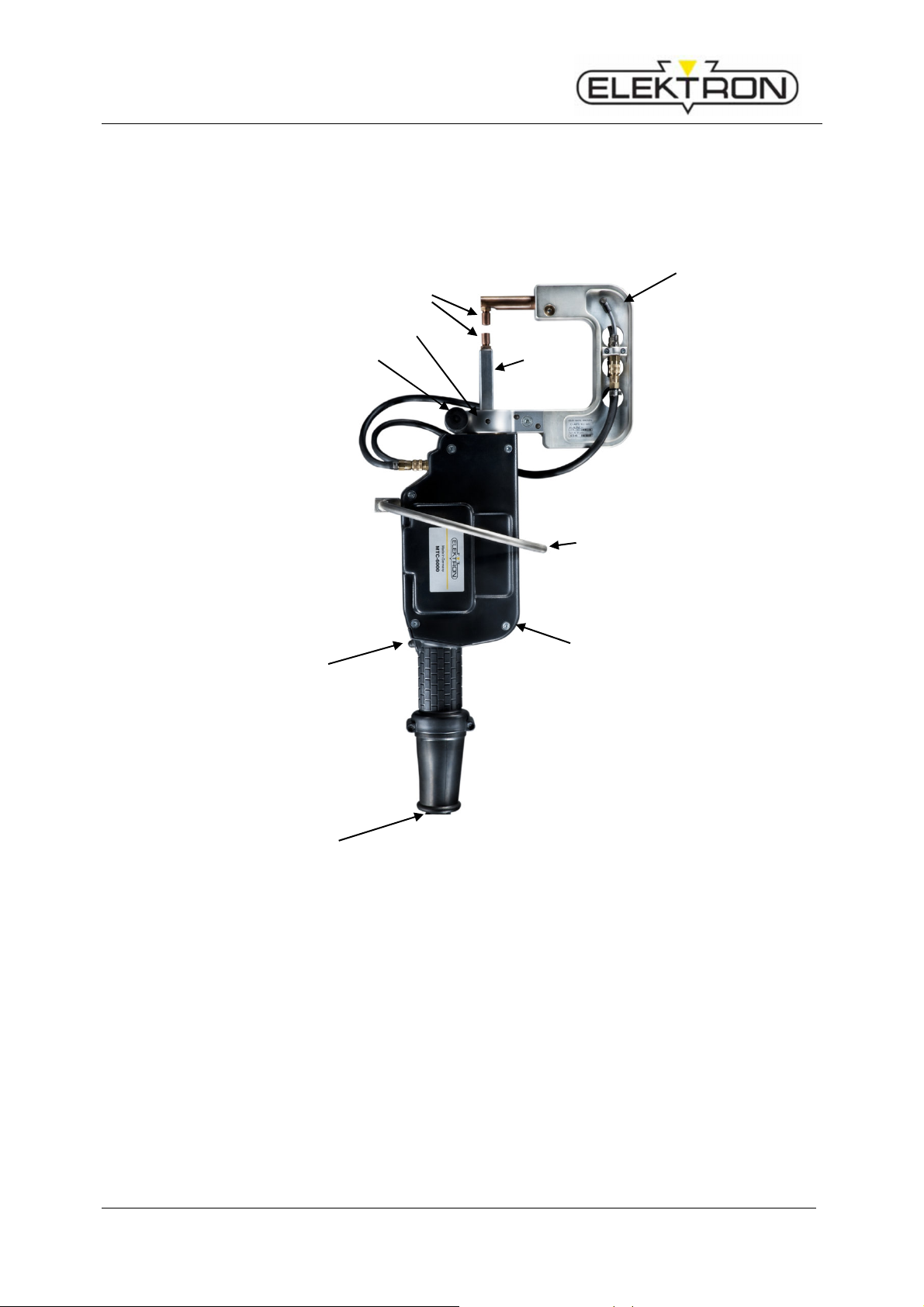
4.1
Overview
4
5
2
3
6
7
1
1. Spot welding pliers
2. C-arm mounting clamp
3. C-arm locking handle
4. Electrode arm
5. Electrode caps
6. Stick electrode, moving
7. Ring bracket
8. Release knob
9. Welding cable
8
9
Fig. 1: Design of the spot welding pliers
13
Page 14

MTC 6000
Safety equipment
4.2
Safety equipment
Emergency stop button (on the resistance welder)
The figure shows the location of the emergency stop button.
It is indicated by the symbol shown on the left.
Fig. 2: Locations of the safety devices
14
Page 15

MTC 6000
Operation
5 Operation
5.1
Connection and preparation of the spot welder
5.1.1
Installation of the ring bracket
1. Position the ring bracket
3. Tighten the screws
2. Insert the screws with the
plastic sleeves (insulation!)
4. Ring bracket screwed to the pliers
15
Fig. 3: Installation of the ring bracket
Page 16

MTC 6000
1
.
co
m-
3
.
Technical data
5.1.2
Connecting the pliers
Fig.4: Central connection of the pliers
Push the central connector of the welding pliers
pletely into the central connection on the machine
(Fig.4/1).
2. Press the locking bracket downwards (Fig.4/2.).
Connect water cooling of the pliers.
Fig.5: Water cooling of the pliers
16
Page 17

CAUTION! Risk of scalding from escaping hot water!
CAUTION! Risk of slipping due to escaping water!
WARNING! Risk of injury from sudden release of the welding tool!
2
3
Knob
5.1.3
Risk of scalding
Risk of slipping
Preparation of the welding pliers
When changing a tool with the machine switched on, welding current or pliers movements can be accidentally triggered. Risk of crushing. Therefore:
– First prepare the welding pliers/welding gun and then switch on the machine.
– If tool changing is necessary during work, be sure to switch off the machine first.
ATTENTION!
Switch off the coolant pump before changing the electrode arm.
Hot water can splash out when disconnecting the coolant hoses. Therefore:
– Wear protective gloves.
– Pull off the coolant hoses carefully.
MTC 6000
Operation
Water can splash out when disconnecting the coolant hoses. Therefore:
– Wipe up any water on the floor.
The device switches automatically to the correct pliers symbol.
Place the electrode arm into the pliers, align and tighten (see 5.1.3.1).
Align the electrodes (see 5.1.3.3).
Tighten the electrode clamping screw.
5.1.3.1 Replacement of the electrode arm
Pins
Fig.6: Replacement of the electrode arm
1. Loosen the electrode arm at the knob (Fig. 6).
2. Press in the ring of the water plug connector
and hold depressed.
3. Pull the coolant line out of the plug connector.
4. After disconnecting the coolant lines, loosen the knob of the C-arm
and pull the C-arm off the pliers by turning the arm so that the pins
of the C-arm are aligned with the grooves in the pliers.
5. Push the new C-arm onto the pliers, align vertically and tighten the
knob of the C-arm.
6. Push the coolant lines into the plug connectors.
2
3
17
Page 18

MTC 6000
1
.
NOTE!
plates, the electrode caps have to be milled or replaced
Technical data
5.1.3.2 Replacement of the electrode caps
Loosen the electrode caps using the electrode cap wrench or an
equivalent tool (Fig.7).
2. Turn in clockwise direction, otherwise the cone will be loosened.
3. Push new electrode caps onto the electrode head and press into
position.
Fig.7: Replacement of the elec-
trode caps
A good condition of the electrode caps is important for
good welding results.
Particularly when welding HSS plates and coated
after 50 welding operations at the latest (milling tool,
see accessory catalogue).
18
Page 19

Warning:
5.1.3.3 Aligning the electrodes with one another
Ensure that the electrodes are correctly aligned in all direc-
tions.
MTC 6000
Operation
Fig.8: "The electrodes must
be aligned"
5.2
Preparation of the welding area
The plates must be ground down to the bare metal at the contact point of the spot electrode
with the plate.
Take care not to damage galvanised surfaces. In the case of insulating intermediate layers
such as spot welding primer, electrical contact (auxiliary connection) first has to be made using a vice-grip wrench. Then set the first welding point directly alongside this contact.
5.3
Welding with the spot welding pliers
Electromagnetic fields!
Wear protective goggles and protective gloves!
The electrodes get hot!
Flying sparks!
− Turn on the machine at the mains switch (see operating manual
of the power pack)
− Connect the machine to the compressed air grid.
− Important: At the end of the welding operation, allow the coolant
pump to run for a few more minutes to prevent any build-up of
heat.
Ensure an adequate supply of compressed air, working pressure
min. 6 bar!
i
Working pressure is 8 bar! For the MTC 6000 pliers the value
should be 6 bar / 90 psi.
Insufficient pressure results in extreme weld spattering and the
weld points can burn through.
19
Page 20

MTC 6000
Technical data
5.4
Welding settings with the MI-100control
Fig. 9: Selection of welding operation
Select the welding operation with the buttons EF, e.g.
a - HSS plates
b - 3-layer plate joint
c - Galvanised plate
Several options can be selected at the same time.
During welding, hold the trigger knob of the pliers depressed until the welding process is terminated automatically.
s
)
) see Fig. 3
)
Example of a welding programme sequence (see Fig. 4):
A – Prepressing 1 sec.
C – Welding time, depending on setting
A – Post-pressing 1 sec.
20
Fig. 10: Welding programme
sequence
Page 21

Welding oper
a-
Ratio of
Plate thic
k-
Setting
Selection
5.5
List of possible setting options in keyboard mode
MTC 6000
Operation
tion
plate thicknesses
d1 = d2 =
d3
d2 ≈ d3
ness
to approx.
0.8 + 0.8 +
0.8
1.0 + 1.0 +
1.0
1.5 + 1.5 +
1.5
2.0 + 2.0 +
2.0
2.0 + 0.8 +
0.8
0.8 + 1.0 +
1.0
0.8 + 1.5 +
1.5
0.8 + 2.0 +
2.0
0.8 + 3.0 +
3.0
value
d1 + d2 + d3
d1 < d2 <
d3
≤
3
Select the
next higher
setting
(*) optional ON or OFF
(!) "3 plates" OFF
21
Page 22

MTC 6000
Compressed air supply
Specification
Value
Unit
Ambient conditions
Specification
Value
Unit
Welding pliers
Specification
Degree of fulfilment
Technical data
6 Technical Data
With direct welding current measurement in the pliers head (pneumatic, water-cooled)
Weight
Specification Value Unit
with cable and C-arm 85 9.7 kg
Working pressure 6 – 10 bar
Quality clean, dry and oil-free
Ambient temperature, max. 40 °C
Relative humidity, max.
(no condensation)
85 %
Exposure limits in accordance
with EU Directive 2004/40/EC
– reliably satisfied at dis-
tances ≥ 20 cm
perpendicularly to the
pliers window
– reliably satisfied at
distances of ≥ 1 cm
from the welding cable
22
Page 23

7 INDEX
A
After-sales service ........................................... 6
C
Caution ............................................................ 4
Coolant pump ................................................ 19
Copyright ......................................................... 6
D
Danger ............................................................. 4
Design ............................................................ 13
E
Ear protectors ................................................ 8
Electricity ................................................... 4, 11
Electrode arm .......................................... 13, 17
Electrode caps ............................................... 13
Electromagnetic fields ............................... 4, 19
Emergency stop button .................................. 14
Emergency stop palm button ......................... 10
Explanation of symbols .................................... 4
F
Face mask ...................................................... 8
Flying sparks ................................................. 19
Function ......................................................... 13
H
Health-endangering substances ...................... 4
Hexagon head bolts ....................................... 17
Hot surface ...................................................... 5
L
Liability disclaimer ........................................... 6
M
Moving machine parts ............................... 4, 11
MTC 6000
Index
N
Note................................................................. 5
O
Operation ...................................................... 15
P
Packaging ..................................................... 12
Protective work clothes ............................... 8
R
Release knob ................................................ 13
Ring bracket ............................................ 13, 15
Risk of crushing ............................................ 5
Risk of slipping ................................................ 5
Risk of tripping ................................................ 5
S
Safety shoes .................................................. 8
Setting and release knob .............................. 13
Storage ......................................................... 12
T
Technical data ............................................... 22
Transport ....................................................... 12
Transport inspection ..................................... 12
Trigger knob .................................................. 20
W
Warning ........................................................... 4
Welding area ................................................. 19
Welding cable ............................................... 13
Welding operation ......................................... 20
Welding programme sequence ..................... 20
Working pressure .......................................... 19
23
 Loading...