

Page 1

Version:
Made in G e r many
Operating Manual
MULTISPOT MI-100control
Resistance welder
Item no.: 328 010
Revision: 0.9 – Translation
31. July 2013
Be sure you have read and understood this operating
manual before you carry out any works on and / or with
this equipment.
Page 2

© BlitzRotary GmbH
Branch Bremen
Hinterm Sielhof 22
D-28277 Bremen
Germany
Phone: +49 (0)421 / 54 90 6 - 906
Fax: +49 (0)421 / 54 90 6 - 19
E-Mail: vertrieb@elektron-bremen.de
Internet: www.elektron-bremen.de
Release:
BlitzRotary GmbH Branch Bremen
2
Page 3

Resistance welder MULTISPOT MI-100control
Table of contents
1
General Information .............................................................................................. 6
1.1 Information concerning the operating manual .......................................................................... 6
1.2 Copyright ................................................................................................................................... 6
1.3 Disclaimer ................................................................................................................................. 6
1.4 Symbols .................................................................................................................................... 7
1.5 Warranty and guarantee ........................................................................................................... 9
1.6 Customer service ...................................................................................................................... 9
2
Health and safety ................................................................................................ 10
2.1 Intended purpose .................................................................................................................... 10
2.2 Responsibilities of the operating company ............................................................................. 10
2.2.1
2.2.2
2.2.3
2.3 Particular dangers ................................................................................................................... 14
2.3.1
2.3.2
2.3.3
2.4 Correct behaviour in accidents and dangerous situations ...................................................... 17
2.5 Measures to be taken in case of work at the device ............................................................... 17
2.6 Safety devices ......................................................................................................................... 18
2.7 Safety labels and markings on this equipment ....................................................................... 19
2.7.1
2.7.2
2.7.3
2.7.4
2.8 Spare and wear parts.............................................................................................................. 20
2.9 Waste management and environmental protection ................................................................ 21
General responsibilities ........................................................................................... 10
Requirements to personnel ..................................................................................... 12
Personal protective equipment (PPE) ..................................................................... 13
Dangers due to the equipment ................................................................................ 14
Dangers due to the work environment .................................................................... 16
Dangers to this equipment and other property ........................................................ 16
On the flap cover ..................................................................................................... 19
Signs on the backside ............................................................................................. 19
On the balancer ....................................................................................................... 20
On the control board ................................................................................................ 20
Table of contents
3
Transport, packaging, storage ........................................................................... 22
3.1 Safety during transport............................................................................................................ 22
3.2 Symbols on packaging ............................................................................................................ 22
3.3 Unpacking ............................................................................................................................... 22
3.4 Acceptance after shipping ...................................................................................................... 23
3.5 Handling .................................................................................................................................. 23
3.5.1
Forklift truck ............................................................................................................. 23
3.5.2
Moving equipment to the site .................................................................................. 24
3.6 In case of return of goods / further transport needs ............................................................... 25
3.7 Storage ................................................................................................................................... 25
4
Design and functionality .................................................................................... 26
4.1 Overview ................................................................................................................................. 26
4.2 Description .............................................................................................................................. 26
4.3 Display and control elements .................................................................................................. 27
4.3.1
On the display and control panel ............................................................................. 27
4.3.2
On the inverter control unit ...................................................................................... 28
4.4 Connections ............................................................................................................................ 28
3
Page 4

Resistance welder MULTISPOT MI-100control
Table of contents
4.4.1
Connections on the front side .................................................................................. 28
4.4.2
Connections on the backside .................................................................................. 29
4.5 Accessories ............................................................................................................................. 30
4.5.1
Optional accessories ............................................................................................... 30
4.5.2
Tools required .......................................................................................................... 30
5
Installation ........................................................................................................... 31
5.1 Before installation ................................................................................................................... 31
5.1.1
Preliminary works .................................................................................................... 31
5.2 Filling up cooling water tank.................................................................................................... 31
5.3 Ventin coolant circuit ............................................................................................................... 32
5.4 Assembling the balancer ......................................................................................................... 33
5.5 Electrical connections ............................................................................................................. 34
5.6 Connecting the pneumatics .................................................................................................... 35
5.7 Connecting the pliers .............................................................................................................. 36
5.8 Connecting the welding gun .................................................................................................... 37
6
Operation ............................................................................................................. 38
6.1 Preliminary works before welding ........................................................................................... 38
6.1.1
Preparing the sheets ............................................................................................... 38
6.1.2
Preparing welding pliers .......................................................................................... 38
6.1.3
Checks before switching on ..................................................................................... 41
6.2 Switching on ............................................................................................................................ 42
6.3 Basic settings .......................................................................................................................... 43
6.3.1
Set languages .......................................................................................................... 43
6.3.2
Register welder ........................................................................................................ 44
6.4 Recurring settings ................................................................................................................... 45
6.4.1
Maintaining electrode caps ...................................................................................... 45
6.4.2
Selecting control mode ........................................................................................... 45
6.4.2.1 Keyboard operation .................................................................................. 46
6.4.2.2 Setting welder in mode “Keyboard operation”.......................................... 47
6.4.2.3 OEM programs ......................................................................................... 48
6.4.2.4 Free mode ................................................................................................ 49
6.4.3
Electrode recognition ............................................................................................... 51
6.4.4
Manual tool selection ............................................................................................... 52
6.4.5
Switching off the cooling water pump ...................................................................... 53
6.5 Important information concerning welding .............................................................................. 53
6.6 Calling up welding parameters................................................................................................ 57
6.7 Settings in the service menu ................................................................................................... 57
6.7.1
Service menu settings (page 1) ............................................................................... 58
6.7.1.1 Enter order data ....................................................................................... 58
6.7.1.2 Concluding an order ................................................................................. 58
6.7.1.3 Administering programs ........................................................................... 59
6.7.1.4 Emptying cooling system ......................................................................... 59
6.7.1.5 Registering welder ................................................................................... 59
6.7.1.6 Activating fuse protection ......................................................................... 59
6.7.1.7 Setting languages .................................................................................... 60
6.7.1.8 Setting time and date ............................................................................... 60
6.7.2
Service menu: settings (page 2) .............................................................................. 60
6.7.2.1 Calling up electrode-cap service mode .................................................... 60
4
Page 5

Resistance welder MULTISPOT MI-100control
6.7.2.2 Changing configuration ............................................................................ 61
6.7.2.3 Loading most recent configuration ........................................................... 61
6.7.2.4 Storing all welding jobs ............................................................................ 62
6.7.2.5 Switching off weld rules ........................................................................... 63
6.7.2.6 Calling up status and error messages ..................................................... 63
6.7.2.7 Calling up the software version ................................................................ 64
6.7.2.8 Calling up current and voltage values ...................................................... 64
6.7.2.9 Modifying service address ....................................................................... 65
6.8 Updating software ................................................................................................................... 65
6.9 Operating the welding gun ...................................................................................................... 67
6.9.1
Push spot welding ................................................................................................... 67
6.9.2
Pulling-out dents with washer .................................................................................. 68
6.9.3
High-speed planishing hammer “SAH” (special accessory) .................................... 69
6.9.4
Pushing-in dents ...................................................................................................... 70
6.9.5
Shrinking sheet ........................................................................................................ 70
6.9.6
Welding-on threaded studs ..................................................................................... 71
6.9.7
Welding-on T-pins ................................................................................................... 72
6.9.8
Fixing sheet metal parts (tacking) ........................................................................... 73
6.9.9
Water-cooled spot welding gun (special accessory) ............................................... 73
6.9.10 Connection of Airpuller/ Dentpuller .......................................................................... 73
Table of contents
7
Troubleshooting .................................................................................................. 74
7.1 Health and safety during troubleshooting ............................................................................... 74
7.2 Error messages and troubleshooting tables .......................................................................... 74
7.2.1
Problems displayed on the control panel ............................................................... 74
7.2.2
Problems NOT displayed on the control panel ....................................................... 78
7.2.3
Possible causes and remedies in case of unsatisfactory welding results ............... 79
8
Maintenance ........................................................................................................ 80
8.1 Maintenance schedule ............................................................................................................ 80
8.2 Carrying out maintenance jobs ............................................................................................... 80
8.2.1
Cleaning .................................................................................................................. 81
8.2.2
Maintaining the pneumatic unit ................................................................................ 81
8.2.3
Replacing water filter ............................................................................................... 82
8.2.4
Empty cooling water tank ........................................................................................ 83
8.3 Measures to be taken after maintenance ............................................................................... 84
9
Specifications ...................................................................................................... 85
9.1 Dimensions and weights ......................................................................................................... 85
9.2 Power requirements ................................................................................................................ 85
9.3 Supplies .................................................................................................................................. 86
9.4 Working conditions .................................................................................................................. 86
9.5 Exposure limit values .............................................................................................................. 86
9.6 Type plates ............................................................................................................................. 86
10 Index .................................................................................................................... 87
11 Appendix.............................................................................................................. 89
11.1 Training Report ....................................................................................................................... 89
5
Page 6

Resistance welder MULTISPOT MI-100control
General Information
1 General Information
1.1 Information concerning the operating manual
This operating manual will enable you to work efficiently and safely with this equipment.
The manual is an essential part of this product and must be stored ready at hand not far from the
equipment so that people can use it at any time without any problems. Operators must read and
understand the manual before they carry out any works. Compliance with any and all information
contained herein concerning health, safety and safe behaviour and procedures is a prerequisite for
safe work.
Shall apply in addition: Any and all local accident prevention regulations, any and all general safety
regulations that may apply to the scope of application of this equipment.
Pictures, drawings etc. contained in this operating manual are supposed to convey a general
understanding of facts. In details, they may deviate from the reality you encounter.
Besides this operating manual, there may be specific instructions for units, components etc.
They shall apply accordingly.
1.2 Copyright
This operating manual is protected by copyright. It may be used for internal purposes, exclusively.
The manual and / or its contents may not be relinquished to third parties and / or communicated,
processed, used and / or reproduced in any way or form whatsoever (not even in excerpts and / or for
internal purposes) without the prior written consent of the manufacturer.
Contravention shall entail damage claims.
All other rights reserved.
1.3 Disclaimer
Any and all information contained in this operating manual has been written on the basis of pertinent
standards and regulations, the state of the art, and the long-standing insights and experience of our
staff.
The manufacturer cannot be made liable for damage due to:
Non-compliance with this operating manual
Non-compliance with the purpose and intent of this equipment
Deployment of unskilled personnel
Unauthorised constructional changes, alterations etc.
Unauthorised changes, modifications etc. to design and engineering etc.
Use of unauthorised spare and wear parts
The scope of the delivery you actually receive may deviate from explanations and / or representations
in this manual - if and when you ordered special options, your equipment is a special design and / or
technical progress facilitates improvements.
Shall apply: any and all obligations and stipulations of the Delivery Contract, the General Terms of
Business and Terms of Supply and Delivery of the manufacturer as well as any and all legal
stipulations and regulations in force on the day the Contract was concluded.
We constantly strive to further develop and improve our products and their functionality. We, therefore,
reserve the right to implement technical changes without notice.
6
Page 7
Resistance welder MULTISPOT MI-100control
DANGER!
WARNING!
CAUTION!
CAUTION!
Electric current!
Electromagnetic fields!
Crushing!
Hot surfaces!
Hot liquids!
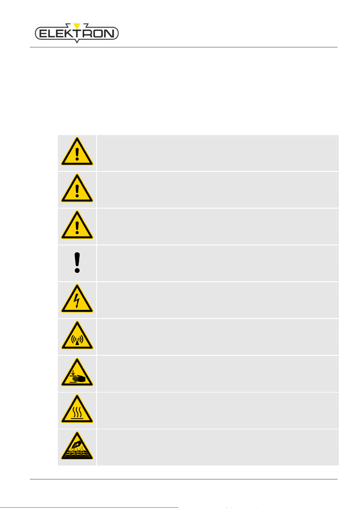
1.4 Symbols
Safety information
This manual uses symbols to highlight important safety information. In addition, there is always a
signal word heading the information indicating the severity of the danger or hazard that may be
encountered.
Be sure to comply with any and all safety information. Proceed with care and circumspection.
Prevent accidents and damage to people and property.
Warnings
General Information
… indicates a situation that is imminently dangerous and will entail the death of people
and severe injuries unless it is properly avoided and prevented.
... indicates a situation that may become dangerous and may entail the death of people
and severe injuries unless it is properly avoided and prevented.
... indicates a situation that may become dangerous and may entail medium and small
injuries unless it is properly avoided and prevented.
… indicates a situation that may become critical and may entail damage to property
unless properly avoided and prevented.
Electricity constitutes a danger to life and limb.
Life hazard for persons with heart pacemakers, or other magnetically influenced
implants. Damage to equipment.
As long as the unit is in operation, risk of injury.
Risk of burns from hot surfaces.
Danger of scalding from escaping hot coolant!
7
Page 8

Resistance welder MULTISPOT MI-100control
Harmful substances!
Risk of stumbling!
Slip hazard!
Electromagnetic fields!
Electromagnetic fields!
Electromagnetic fields!
S
afety clothing
Safety shoes
Face screen
Welder's gloves
General Information
Danger of toxic, harmful vapours at least.
Risk of injury due to falls.
Risk of slipping due to leaking water.
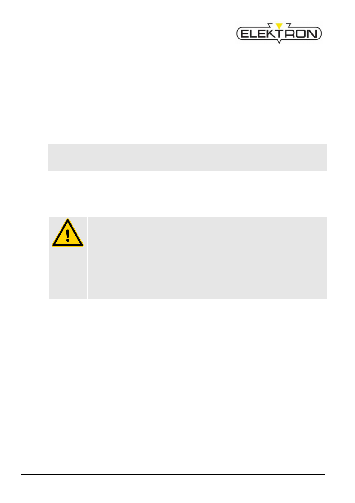
Prohibitions
Hazard to persons with pacemakers.
Persons who may suffer health risks due to the influence of electromagnetic fields must
not approach this equipment.
Mandatorys
Hazard to persons with magnetisable implants.
Persons who may suffer health risks due to the influence of electromagnetic fields must
not approach this equipment.
Hazard to magnetisable objects
Magnetisable data carriers and similar objects that may suffer from magnetism must not
be brought close to this equipment.
…is a tight-fitting sort of special clothing that is not inflammable, covers arms and legs
completely and tears easily (instead of getting pulled in). Its main purpose is to protect
against burns.
…protects the wearer's feet against falling objects, slippery surfaces and being run over
by vehicles.
…protects the face and eyes against splashes, flying sparks and other hot particles.
8
…protect the hands against splashes, flying sparks and other hot particles, and prevent
contact with hot surfaces.
Never use wet welder's gloves.
Page 9

Resistance welder MULTISPOT MI-100control
Tips, tricks and recommendations
NOTE!
... highlights information that may be helpful to maintain efficient and trouble-free
operation.
1.5 Warranty and guarantee
The guarantee conditions shall be as stipulated in the General Terms of Business of the manufacturer.
1.6 Customer service
Our customer service will be happy to provide technical support.
For contact information, see page 2 of this manual or the service menu on the control panel.
Please note: Our staff is always eager to learn about new information, insights and / or experience our
customers may derive from the work with our products that may be helpful for their future
improvement.
General Information
9
Page 10
Resistance welder MULTISPOT MI-100control
MULTISPOT MI
-
100control
WARNING!
Misuse may entail danger
!
Health and safety
2 Health and safety
This section contains an overview of the most important health and safety at work aspects in order to
protect employees and to guarantee safe and trouble-free operation.
Non-compliance with any and all of the information, safe behaviour and procedures etc. contained
herein may entail severe health and safety risks.
2.1 Intended purpose
This equipment has been designed and built for the following purpose(s), exclusively, and shall be
used accordingly:
The
maintenance work on car bodies, for stock of up to 3 mm sheet gauge and combinations of up to three
sheets within its specifications and limits of use ( see “Specifications”).
“Intended use” and “intended purpose” shall include proper compliance with any and all information
contained in this operating manual.
Any and all use diverting from and / or going beyond the limits as set by the equipment's intended
purpose and use shall be deemed misuse and may entail dangerous situations.
Misuse of this equipment may entail dangerous situations.
Therefore:
Do not operate this equipment unless clearly within its specs and limits of use
( see “Specifications”).
Be sure to use this equipment for welding sheet metal up to 3 mm, galvanised stock
and sheets made of super speed steel (HSS), exclusively.
Do not misuse this equipment for heating, thawing or perhaps even igniting objects.
Do not use this equipment in explosive atmospheres.
Do not open, alter, modify and / or manipulate etc. this equipment.
The manufacturer shall not be held liable for any and all damage due to misuse of this equipment.
resistance welder serves the sole purpose of spot welding during
2.2 Responsibilities of the operating company
2.2.1 General responsibilities
This equipment has been designed for professional use. The owner / operator or operating company
therefore being a businessman or commercial company, they are subject to any and all legal
obligations concerning health and safety at work.
That means, in addition to this operating manual, any and all accident prevention, health and safety at
work and environmental regulations pertaining to this equipment's scope of application shall apply as
well.
This means in particular:
The operating company must be informed about any and all pertinent health and safety at
10
work regulations and must carry out a risk assessment in order to determine additional
hazards existing under the specific conditions in the specific work environment at the place
of operation. Any and all findings from such a risk assessment must then be used to draw up
additional operating instructions for the operation of this equipment.
Page 11
Resistance welder MULTISPOT MI-100control
Electromagnetic fields!
Electromagnetic fields!
Electromagnetic fields!
Health and safety
During the entire lifetime of this equipment, the operating company must check in regular
intervals whether such additional operating instructions are still up to date and must update
them when necessary.
The operating company must unambiguously determine and communicate responsibilities
concerning the installation, operation, maintenance and cleaning of this equipment.
The operating company must make sure that any person handling this equipment has read
and understood this operating manual. Operating personnel, in addition, must be trained in
regular intervals and must be informed about the dangers existing in connection with this
equipment. (For a draft of a training report form, see “Appendix”)
The operating company must equip operating personnel with suitable personal protective
equipment (PPE) and check it for proper working condition in regular intervals.
Defective PPE must be replaced with new ones.
The operating company must take appropriate and suitable fire protection measures and
make available fire extinguishers and first aid kits.
The operating company is responsible that the equipment is in proper working order at all times.
Therefore:
The operating company must make sure that any and all maintenance jobs described in this
manual are really carried out.
The operating company must have any and all safety labels, markings etc. on the equipment
checked for integrity and readability in regular intervals.
Symbols the operating company must install on access ways and doors
Symbol Meaning
Hazard to persons with pacemakers.
Persons who may suffer health risks due to the influence of electromagnetic fields must
not approach this equipment.
Hazard to persons with magnetisable implants.
Persons who may suffer health risks due to the influence of electromagnetic fields must
not approach this equipment.
Symbols the operating company must install in the immediate vicinity of the equipment
Symbol Meaning
Hazard to magnetisable objects
Magnetisable data carriers and similar objects that may suffer from magnetism must not
be brought close to this equipment.
11
Page 12

Resistance welder MULTISPOT MI-100control
WARNING!
People with insuffic
ient skills may suffer injuries!
Health and safety
2.2.2 Requirements to personnel
Inexpert handling may entail severe damage to persons and property.
Therefore:
Make sure that any and all activities are carried out by skilled personnel, only.
This equipment may be operated only by persons who can be relied on to do their work
properly.
Persons whose capability of reaction is impaired, e. g. by drugs, alcohol or medication, must
not be allowed to handle this equipment.
When selecting suitable operating personnel, be sure to respect occupational regulations
and legislation concerning skills, age etc.
This operating manual specifically names the following types of personnel who must have the
following skills:
Operator / welder
has extensive skills and experience in the field of resistance welding and with the
corresponding preliminary and finishing jobs. The welder / operator has been coached /
trained by employees of ELEKTRON and / or an authorised representative / dealer of
ELEKTRON concerning his tasks and duties and possible hazards in connection with
inappropriate behaviour and confirms this with his signature (see draft of training report form,
“Appendix”).
Service personnel
refer to manufacturer's own service personnel and / or that of his representative / dealer.
Such service personnel have the professional training, skills and experience as well as
knowledge of pertinent regulations to carry out the jobs they accept and to identify, avoid
and prevent hazards on their own and without additional support.
Skilled electrician
has the professional training, skills and experience as well as knowledge of pertinent
regulations to carry out jobs on electrical equipment and to identify, avoid and prevent
hazards on his own and without additional support. A skilled electrician is needed, for
instance, if the conductor cross-section and fuse protection of the operating company's
power grid must be adapted to the special requirements of resistance welding.
12
Page 13

Resistance welder MULTISPOT MI-100control
CAUTION!
Insufficient protection
against injuries
!
S
afety clothing
Safety shoes
Face screen
Welder's gloves
Furthermore
2.2.3 Personal protective equipment (PPE)
Defective safety clothing may not constitute a proper protection against injuries.
Therefore:
Be sure to check PPE for integrity and good working condition before you start any
works.
Replace defective PPE.
Consider manufacturer's instructions and expiration dates, when and where
applicable.
Wearing PPE during work is essential to minimise health and safety risks.
Be sure to be always wearing the appropriate PPE for the job at hand.
Be sure to take note of and comply with warning signs concerning PPE that may be installed
at the workplace.
When working, always wear:
Health and safety
…is a tight-fitting sort of special clothing that is not inflammable, covers arms and legs
completely and tears easily (instead of getting pulled in).
Its main purpose is to protect against burns.
…protect the wearer's feet against falling objects, slippery surfaces and being run over
by vehicles.
In case of special work wear:
…protects the face and eyes against splashes, flying sparks and other hot particles.
…protect the hands against splashes, flying sparks and other hot particles, and prevent
contact with hot surfaces.
Never use wet welder's gloves.
…no long hair, rings, necklaces, watches and / or other sorts of jewellery. Do not carry
easily inflammable objects in your pockets (matches, lighters etc.).
13
Page 14

Resistance welder MULTISPOT MI-100control
DANGER!
Electricity consti
tutes a danger to
life and limb!
DANGER!
Electromagnetic fields pose a potentially fatal hazard to people with
Health and safety
2.3 Particular dangers
2.3.1 Dangers due to the equipment
Electricity
Touching live components can result in a fatal electrical shock.
Therefore:
As soon as you notice any damage to insulation, disconnect the power supply and
have the damage repaired.
Do not open this equipment yourself. Have all repairs carried out by service
personnel, exclusively. Have works on electrical equipment carried out by skilled
electricians, exclusively.
Before any and all electrical works: disconnect power, earth and short. Check
whether equipment is really dead.
Keep live components away from liquids and humidity. They may cause short
circuits.
Protect cables against running over, contact with oils, aggressive substances, tools,
pointed and / or hot objects.
When pulling from a socket: Never pull on the cable. Pull on the plug.
Do not use the cable to trail or drag equipment over the floor.
Always grab equipment by the handles provided for that purpose.
Use strain relief clamps to protect cables.
Make sure protective ground conductors have been connected properly.
After disconnecting the welder from the mains the welder still contains residual
current for approx. 15 minutes.
Electromagnetic fields
pacemakers or other magnetisable implants!
Electromagnetic fields affect the functionality of pacemakers and other magnetisable
implants. Electromagnetic fields can irritate human sense organs, nerve and muscle
cells.
Therefore:
Persons with pacemakers or other magnetisable implants must not approach the
work area.
Be sure to put up suitable warning signs.
Be sure to put warning signs on access ways and doors leading to the work area.
Do not guide welding cables along people's heads or spines. (To comply safely with
permissible exposure limits, keep distances ≥ 20 cm. Keep a distance of at least
2 cm between cable assemblies and people's heads / spines.)
14
Page 15
Resistance welder MULTISPOT MI-100control
WARNING!
Splashes and flying sparks constitute a danger of fire and
CAUTION!
Hot surfaces pose a ris
k of burns!
DANGER!
Scalding may occur due to hot water coming out!
DANGER!
Slip hazard due to water coming out!
Health and safety
Splashes, flying sparks
explosion. Splashes and flying sparks pose a risk of injuries!
Welding generates sparks and - hot spatter. They can ignite combustible materials and
generate explosions. Contact with body parts may entail injuries.
Therefore:
Before you tackle any welding jobs, make sure there are no combustible and / or
explosive materials in the work area.
Do not carry out welding jobs in the vicinity of pressure vessels, tanks, oil barrels,
paint cans and / or in a work area with an explosive atmosphere.
Have fire extinguishing gear ready at hand.
Make sure access and escape routes are not blocked.
During any and all welding jobs: be sure to be wearing a face screen, non-
inflammable safety clothing and welder's gloves.
Do not carry easily inflammable objects in your pockets (matches, lighters etc.).
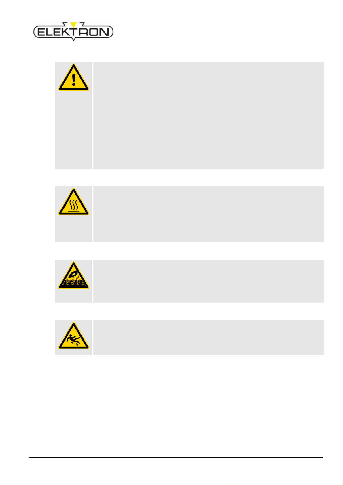
Hot surfaces
Electrodes may heat up to 80 degrees centigrade approx. Stock may have up to
100 degrees right after welding. So there is an acute risk of burning yourself.
Therefore:
Never work without proper safety clothes and gloves near hot components.
Let freshly welded parts cool down to ambient temperature before you go on to
work with them.
Scald hazard
While pulling out the cooling water hoses hot water may come out.
Therefore:
Wear gloves.
Pull out water hoses carefully.
Slip hazard
While pulling out the cooling water hoses water may come out.
Therefore:
Remove water from the floor.
15
Page 16
Resistance welder MULTISPOT MI-100control
WARNING!
Vapours may constitute a dange
r to your health!
WARNING!
Possibility of injuri
es due to stumbling and falling!
CAUTION!
Tipping and toppli
ng may cause damage to property!
CAUTION!
Equipment rolling aw
ay may cause damage to property!
Health and safety
2.3.2 Dangers due to the work environment
Vapours
Stock that has not been properly ground and cleaned before welding may be
contaminated with residues of glues, paints, undercoating products etc. that may
generate harmful or even toxic vapours during welding.
Therefore:
Before you tackle any welding jobs, make sure the sheets you want to weld have
been properly ground and cleaned and are free of residues.
Be sure to be wearing a face screen. Respiratory equipment may be
recommendable in case of doubt.
Stumbling hazards
The work environment may pose stumbling risks. Stumbling and falling may lead to
severe injuries.
Therefore:
Before you tackle any welding jobs, make sure the work area is tidy and free of
clutter and offers enough freedom to move.
Install cables and supply lines in such a way that they do not constitute a stumbling
trap.
When welding, assume a safe and stable working position.
2.3.3 Dangers to this equipment and other property
Tipping and toppling hazards due to high centre of gravity and obstacles during travel
This equipment's centre of gravity is relatively high. In the event the wheels jam and / or
block (due to an obstacle or transverse pull, for instance), there is a danger the
equipment tips over.
Therefore:
Move this equipment always using the handles.
Keep potential obstacles out of the work area.
Install cables and supply lines in such a way that they do not constitute a stumbling
trap.
There is a danger the equipment rolls away because the wheels must not be blocked due to the
tipping and toppling hazard
The wheels of the equipment must not be blocked because this would cause a tipping
and toppling hazard. On the other side, though, this detail causes and increases the
danger the equipment rolls away.
Therefore:
Be sure to operate this equipment only on a flat and even floor.
Proceed with care when moving this equipment.
16
Page 17

Resistance welder MULTISPOT MI-100control
CAUTION!
Display and c
ontrol panel may sustain damage!
Dangers to display and control panel
The display and control panel may sustain damage when being closed if negligent
employees leave objects lingering on the accessory box beneath.
Therefore:
Never put objects on the accessory box beneath the display and control panel.
Proceed with care when closing the flap cover with integrated display and control
panel.
2.4 Correct behaviour in accidents and dangerous situations
Preventive measures
Be prepared to confront accidents and fires.
Be sure to have first aid equipment (kits, blankets etc.) and fire extinguishers ready at hand.
All personnel must know about accident signalling systems, first aid, rescue and escape
equipment.
Keep access ways for ambulances clear and open.
Health and safety
Measures to be taken in case of accidents
Actuate emergency stop. ( see “2.6”.)
Initiate first aid.
Evacuate people from danger zone.
Alert persons in charge.
Alert fire brigade and ambulance service.
Keep access ways for ambulances clear and open.
2.5 Measures to be taken in case of work at the device
De-energise.
Secure against restarting (e. g. pull out mains plug).
Unstressedness determines.
Ground and short circuit.
Neighbouring energized parts cover or provide with gates.
17
Page 18
Resistance welder MULTISPOT MI-100control
WARNING!
Danger! Due to insufficient protection against residual current!
WARNING!
Danger
of life and limb
! Equip
ment may still be under voltage!
Health and safety
2.6 Safety devices
Connection to electrical socket: the device may only be plugged into a socket with a
residual current device and an operable earthing device.
Fig. 1: Emergency stop pushbutton
Emergency stop pushbutton
Hitting the emergency stop pushbutton will shut down the
equipment immediately. After the emergency stop has been
actuated, it must be turned clockwise (cw) to unlock before
the equipment can be switched on again.
Fig. 2: Power switch on the backside
The emergency stop will shut down the equipment, but will not disconnect the power
supply. To accomplish that, push the power switch on the backside of the equipment.
Even then, there may still be components inside that are still under voltage.
Therefore:
In order to disconnect this equipment from the power supply, switch off using the
power switch. Earth components, short circuit and check for residual electricity.
Do not unlock the emergency stop pushbutton before danger has been completely
removed.
Power switch
Turning the power switch to position “0” will disconnect the
power supply immediately (which, basically, has the same
effect as an emergency stop).
18
Page 19
Resistance welder MULTISPOT MI-100control
DANGER!
Electromagnetic fields pose a mortal da
nger to persons with
CAUTION!
Pump damage due to dry running!
2.7 Safety labels and markings on this equipment
2.7.1 On the flap cover
Meaning
Welding generates electromagnetic fields.
Electromagnetic fields pose a potentially fatal hazard to
Fig. 3: Warning sign “Electromagnetic fields” on
the flap cover
pacemakers!
Electromagnetic fields affect the functionality of pacemakers and other magnetisable
implants. Electromagnetic fields can irritate human sense organs, nerve and muscle
cells.
Therefore:
Persons with pacemakers or other magnetisable implants must not approach the
working area.
Be sure to put up suitable warning signs.
Be sure to put warning signs on access ways and doors leading to the work area.
Do not guide welding cables along people's heads or spines. Keep a distance of at
least 2 cm.
people with pacemakers or other magnetisable implants.
Electromagnetic fields also affect magnetisable objects, like
e. g. watches, smart cards etc.
Health and safety
2.7.2 Signs on the backside
Fig. 4: Warning sign on the backside
Pump may sustain damage when running dry.
Pump running dry may sustain damage.
Therefore:
Before starting up, check cooling water level at the level gauge.
If necessary (i. e. if you can't see water in the level gauge), fill up. ( see “5.2”.)
Meaning
Do not operate pump without cooling water.
Pump running dry may sustain damage.
19
Page 20
Resistance welder MULTISPOT MI-100control
CAUTION!
Tipping and toppli
ng may cause damage to property!
WARNING!
Wrong spare and
wear parts constitute a hazard!
Health and safety
2.7.3 On the balancer
Fig. 5: Warning sign on balancer
Danger of tipping by relatively high centre of gravity and any obstacles in the path
This equipment's centre of gravity is relatively high. In the event the wheels jam and / or
block (due to an obstacle or transverse pull, for instance), there is a danger the
equipment tips over.
Therefore:
Move this equipment always using the handles.
Keep potential obstacles out of the work area.
Install cables and supply lines in such a way that they do not constitute a stumbling
trap.
Meaning
Always pull in the direction the guiding wheels are pointing.
In the event of lateral and / or transverse pull, there is a
danger the wheels jam / block and the equipment tips over.
2.7.4 On the control board
Fig. 6: Warning sign on the control board
2.8 Spare and wear parts
Wrong and / or defective spare and wear parts may constitute a safety hazard and may
entail errors, damage and even total destruction.
Therefore:
Always use genuine spare and wear parts made by the manufacturer.
Be sure to buy your spare and wear parts directly from the manufacturer or an authorised dealer.
For contact information see page 2 of this manual or the service menu on the control panel.
Meaning
Do not pull compact flash card unless equipment has been
properly switched off.
Compact flash card might be destroyed otherwise.
20
Page 21

Resistance welder MULTISPOT MI-100control
CAUTION!
Inexpert handling may consti
tute an
environmental hazard!
2.9 Waste management and environmental protection
Inexpert handling of environmentally harmful substances, especially wrong disposal,
may constitute a hazard to the environment.
Therefore:
Be sure to take appropriate measures whenever harmful substances get (or
threaten to get) into the environment. In case of doubt, inform competent local
authorities about the hazard or damage.
Local authorities and specialised waste management companies will be happy to
advise you with your disposal issues.
Please also consider the following information.
Batteries
Batteries contain toxic heavy metals. Batteries are subject to hazardous waste management and must
be collected by specialised companies or taken to special collection centres.
Electronic components
Electronic components and scrap are subject to hazardous waste management and must be collected
by authorised companies.
Health and safety
Other components
Unless you have concluded a return and / or disposal agreement with the manufacturer, please
disassemble and recycle components.
Scrap metals.
Recycle plastic parts.
Other components must be sorted by materials and disposed of accordingly.
21
Page 22
Resistance welder MULTISPOT MI-100control
CAUTION!
Improper transpo
rt may cause damage to property!
CAUTION!
Improper waste disposal
may cause environmental hazards!
Transport, packaging, storage
3 Transport, packaging, storage
3.1 Safety during transport
Inexpert transport
Improper transport may cause damage to property.
Therefore:
When you unload packing units and move them across your premises, proceed with
care. Consider symbols and information on packaging.
Be sure to transport equipment as described hereinafter. ( see “3.5”.)
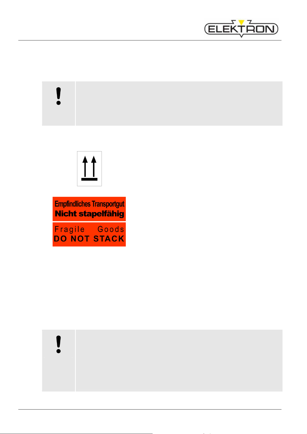
3.2 Symbols on packaging
Top
The arrows point towards the ‘roof’ of the packing unit. This
side up. The arrows must always point up; otherwise the
Fig. 7: Top
contents of the packing unit could be damaged.
Fig. 8: Do not stack
3.3 Unpacking
1. Do not remove packaging until immediately before installation.
During unpacking, do not use pointed tools.
2. Keep the original pallet (Fig. 9) in case of any further transport needs (return of goods,
further transport).
3. Recycle packing materials.
What to do with packing materials
Do not stack
Fragile goods. Do not stack; otherwise the contents of the
packing unit could be damaged.
Packing materials are valuable raw materials. In many cases, they can be recycled,
i. e. used again for packaging or in some other way or they can be further processed or
treated in some way.
Therefore:
Be sure to dispose of packing materials in sustainable manner and / or according to
local laws and regulations.
Observe local waste management legislation. In case of doubt, contact a
specialised company.
22
Page 23
Resistance welder MULTISPOT MI-100control
3.4 Acceptance after shipping
Check packing units immediately after delivery. Check for integrity, missing pieces and damage.
If you detect any external shipping damage, proceed as follows:
Do not accept delivery; or accept under reserve.
Report damage on carrier's shipping papers or delivery ticket.
Initiate complaint procedure.
NOTE!
Be sure to register a complaint as soon as a defect has been detected. Claims for
damages may be brought forward only within the deadlines set for complaints.
3.5 Handling
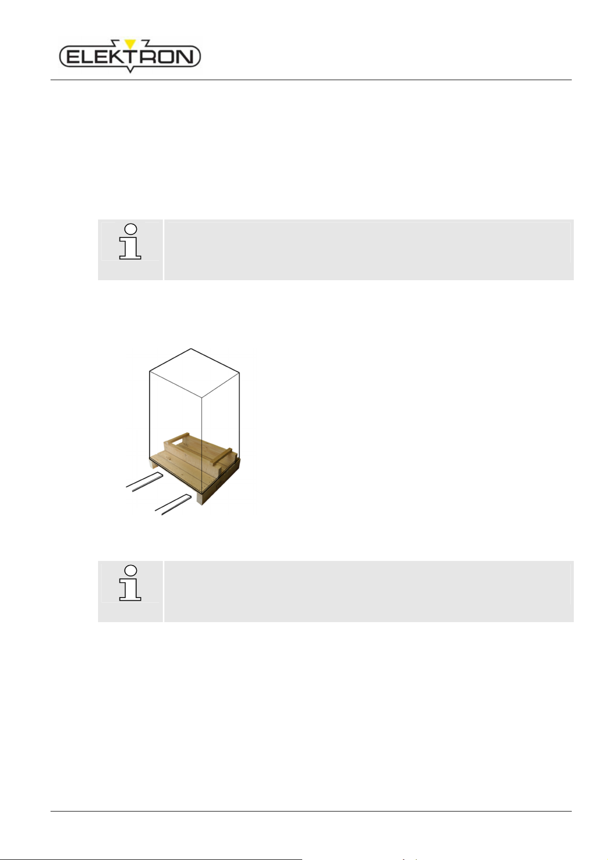
3.5.1 Forklift truck
Transport, packaging, storage
Fig. 9: Using a forklift truck
NOTE!
Keep the original pallet in case of any further transport needs (return of goods, further
transport).
Packing units on pallets may be handled with a forklift truck,
as long as the following conditions are fulfilled:
The forklift truck must be certified for the weight of the
packing unit at hand.
The operator must have a licence to drive forklift trucks.
Packing units may have very high centres of gravity.
Make absolutely sure they cannot tip over.
23
Page 24

Resistance welder MULTISPOT MI-100control
CAUTION!
Tipping and toppli
ng may cause damage to property!
CAUTION!
Equipment rolling aw
ay may cause damage to property!
Transport, packaging, storage
3.5.2 Moving equipment to the site
Fig. 10: Warning sign on balancer
There is a danger of tilting
This equipment’s centre of gravity is relatively high. In the event the wheels jam and / or
block (due to an obstacle or transverse pull, for instance), there is a danger the
equipment tips over.
Therefore:
Move this equipment always using the handles.
Keep potential obstacles out of the work area.
Securely stow cables and wires.
When moving around, always grip equipment by the handle
provided for that purpose.
There is a danger the equipment rolls away because the wheels must not be blocked due to the
tipping and toppling hazard.
The wheels of the equipment must not be blocked because this would cause a tipping
and toppling hazard. On the other side, though, this detail causes and increases the
danger the equipment rolls away.
Therefore:
Be sure to operate this equipment only on a flat and even floor.
Proceed with care when moving this equipment.
24
Page 25

Resistance welder MULTISPOT MI-100control
CAUTION!
Improper transport conditio
ns may cause damage to property!
Transport, packaging, storage
3.6 In case of return of goods / further transport needs
1. Drain cooling water tank completely. see “8.2.4”.
2. Use original transport pallet. (see Fig. 9)
3. Use packing materials that correspond to original packing materials.
4. Mark packing materials with symbols as shown in “3.2”.
Packaging with inappropriate dimensions, quality or weight, or cooling water left in
coolant tank may cause damage during transport.
Therefore:
Be sure to completely drain coolant tank before transport.
Use packaging of appropriate size and quality.
3.7 Storage
Storage conditions:
Do not store packing units outdoors.
Provide for dry and dust-free storage.
Protect against aggressive media.
Protect against direct sun exposure.
Protect against mechanical shocks and vibrations.
Storage temperature: -10 to 50 degrees centigrade.-50 to 122 degrees Fahrenheit.
Rel. humidity: 85 % max.; no dew.
When storing equipment longer than three months, check general conditions of all parts and
packaging in regular intervals. If and when necessary, refresh or renew corrosion protection.
25
Page 26
Resistance welder MULTISPOT MI-100control
Design and functionality
4 Design and functionality
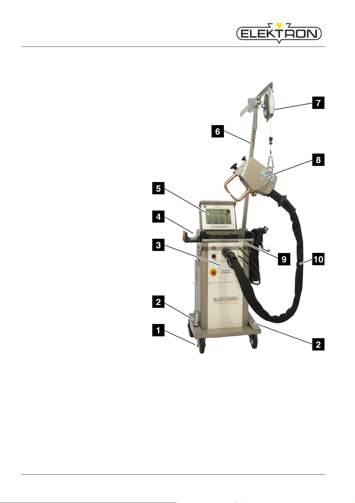
4.1 Overview
1 Running gear
2 Support for tools
3 Inverter control unit
4 Cable or welding pliers support
5 Display and control panel
6 Balancer support
7 Balancer
8 Welding pliers
9 Handle
10 Welding pliers supply lines
Fig. 11: MULTISPOT system (standard)
4.2 Description
The MULTISPOT MI-100control resistance welder has been designed and built with the special
requirements of body makers and maintenance in mind.
The inverter, which provides the power for welding, is controlled by a microprocessor. That way, weld
current and weld time will be adjusted automatically on the basis of the selected operating mode,
sheet gauge and welding job.
The automatic current adjustment facilitates a perfect reproducibility of welding results.
The additional power needed for adjustment is taken from the mains.
26
Page 27
Resistance welder MULTISPOT MI-100control
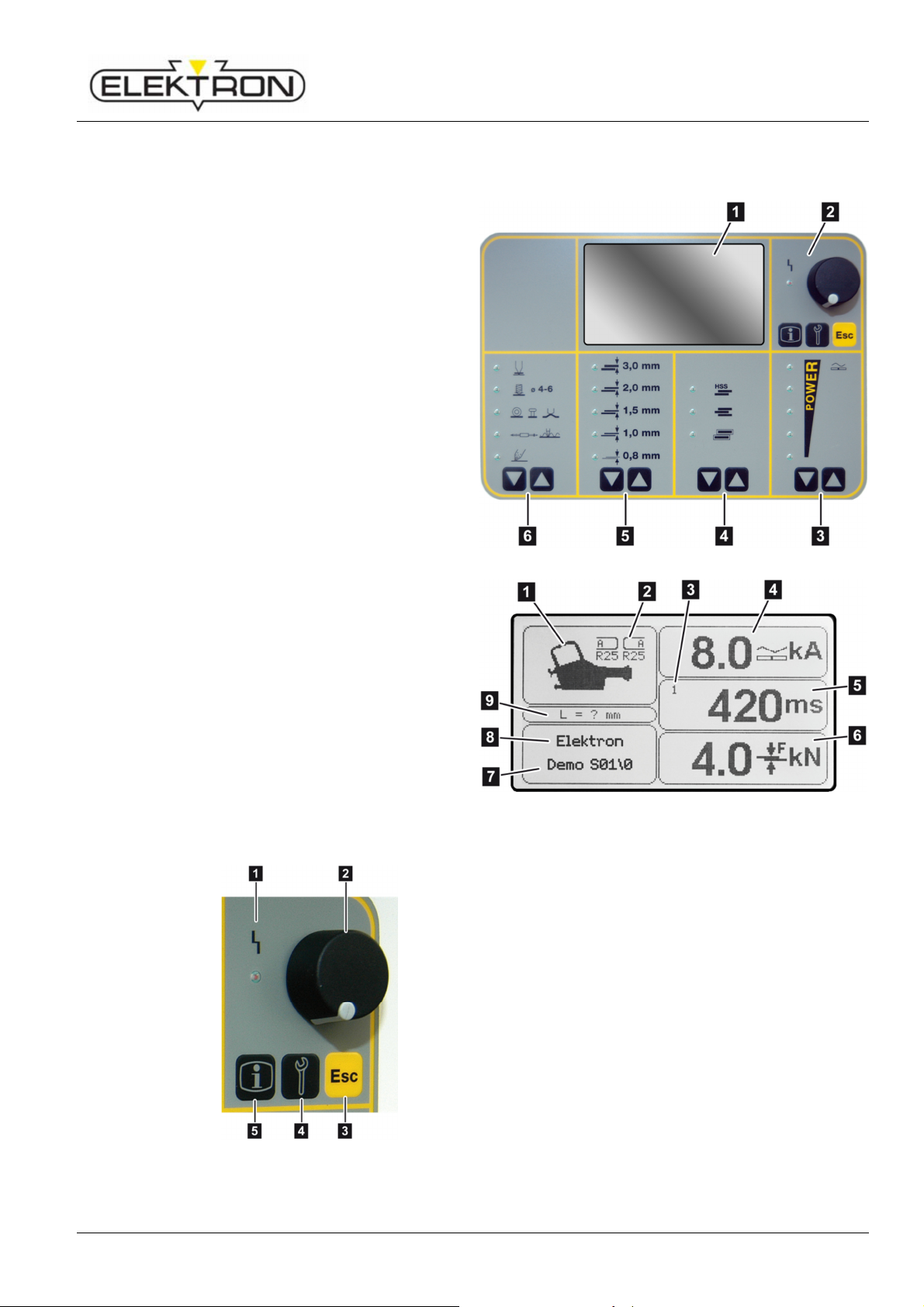
1
4.3 Display and control elements
4.3.1 On the display and control panel
1 Display
see also Fig. 13
2 Selection elements
see also Fig. 14
3 Touch key for power selection
4 Touch key for selecting welding jobs
(from top to bottom):
high strength steel (HSS)
3 layer sheets
galvanised sheets
5 Touch key for selecting sheet gauges
6 Touch key for selecting a welding gun
Design and functionality
Tools detected automatically
2 Electrode caps required for welding
program
3 No. of pulses (1 – 36)
4 Weld current set
5 Weld time set
(Total of all current times)
6 Contact pressure set
7 Program name
8 Operating mode
9 Projection of electrodes
(i. e. actual length minus engaging area)
Fig. 14: Detail from Fig. 12
Fig. 12: Display and control panel
Fig. 13: Detail from Fig. 12
1 LED “Malfunction”,
see “7.2.2”, work cannot continue as long as the
LED is on.
2 Control knob,
for selecting and confirming menu items.
3 “ESC”,
can have different functions: “Cancel” or “Pump
OFF”, depending on menu.
4 “Service”,
for selecting the service menu.
see “6.7.1” and “6.7.2”.
5 “Info”,
calls up welding parameters; see “6.6”.
27
Page 28

Resistance welder MULTISPOT MI-100control
Design and functionality
4.3.2 On the inverter control unit
Fig. 15: Power switch (in „OFF” position)
4.4 Connections
4.4.1 Connections on the front side
The power switch (Fig. 15) is for switching the
power supply on and off.
Fig. 16: Connections on the front side
1 Pressure gauge
displays input pressure.
2 Pressure reducer
continuous adjustment of input pressure
3 Central connection point for weld current,
compressed air and control voltage of the
welding pliers
4 Coolant outlet
5 Coolant return
6 Connection for sensors
7 Emergency stop pushbutton
shuts down equipment immediately.
28
Page 29
Resistance welder MULTISPOT MI-100control
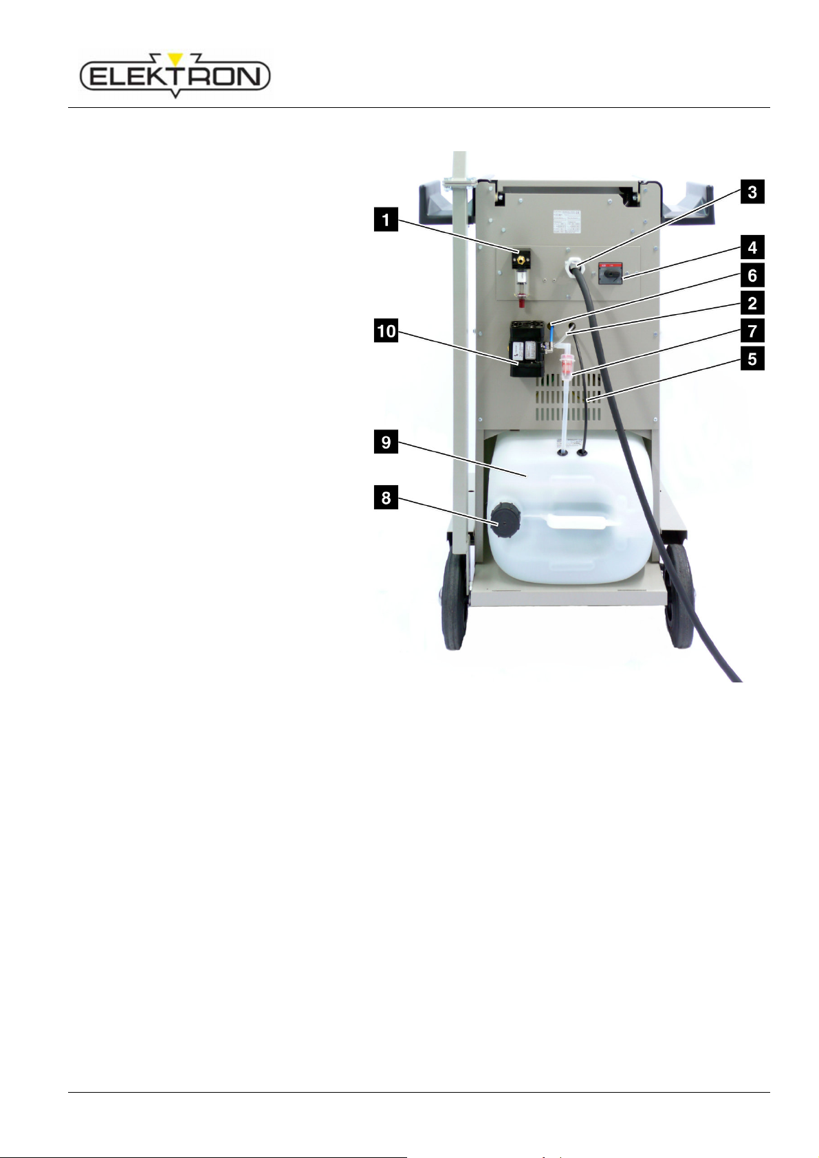
4.4.2 Connections on the backside
1 Compressed-air filter unit
2 Coolant-pump air supply
3 Power cord
4 Power switch
5 Coolant outlet towards pump
6 Coolant return
7 Water filter
8 Cooling-water tank cap
9 Cooling-water tank
Design and functionality
Fig. 17: Connections on the backside
29
Page 30

Resistance welder MULTISPOT MI-100control
Design and functionality
4.5 Accessories
4.5.1 Optional accessories
Additional cooler (Fig. 18),
to increase service life of welder
Electrode arms / hoops
Electrode caps
Fig. 18: Optional cooler
4.5.2 Tools required
Fig. 19: Key for electrode caps
Key for electrode caps (Fig. 19)
NOTE!
Find our complete range of products and order information at www.elektron-bremen.de.
30
Page 31
Resistance welder MULTISPOT MI-100control
1.
5 Installation
5.1 Before installation
5.1.1 Preliminary works
Check operating conditions according to specifications.
( see “9.4”.)
If necessary, allow equipment time to adapt to ambient temperature SLOWLY.
Make sure that operating company’s supply systems comply with specifications.
( see “9.2”.)
Before you start any works, make sure the work area is tidy, clean and free of clutter and
offers enough room to move.
Make sure your tools are complete and in good working order.
Do wear safety shoes.
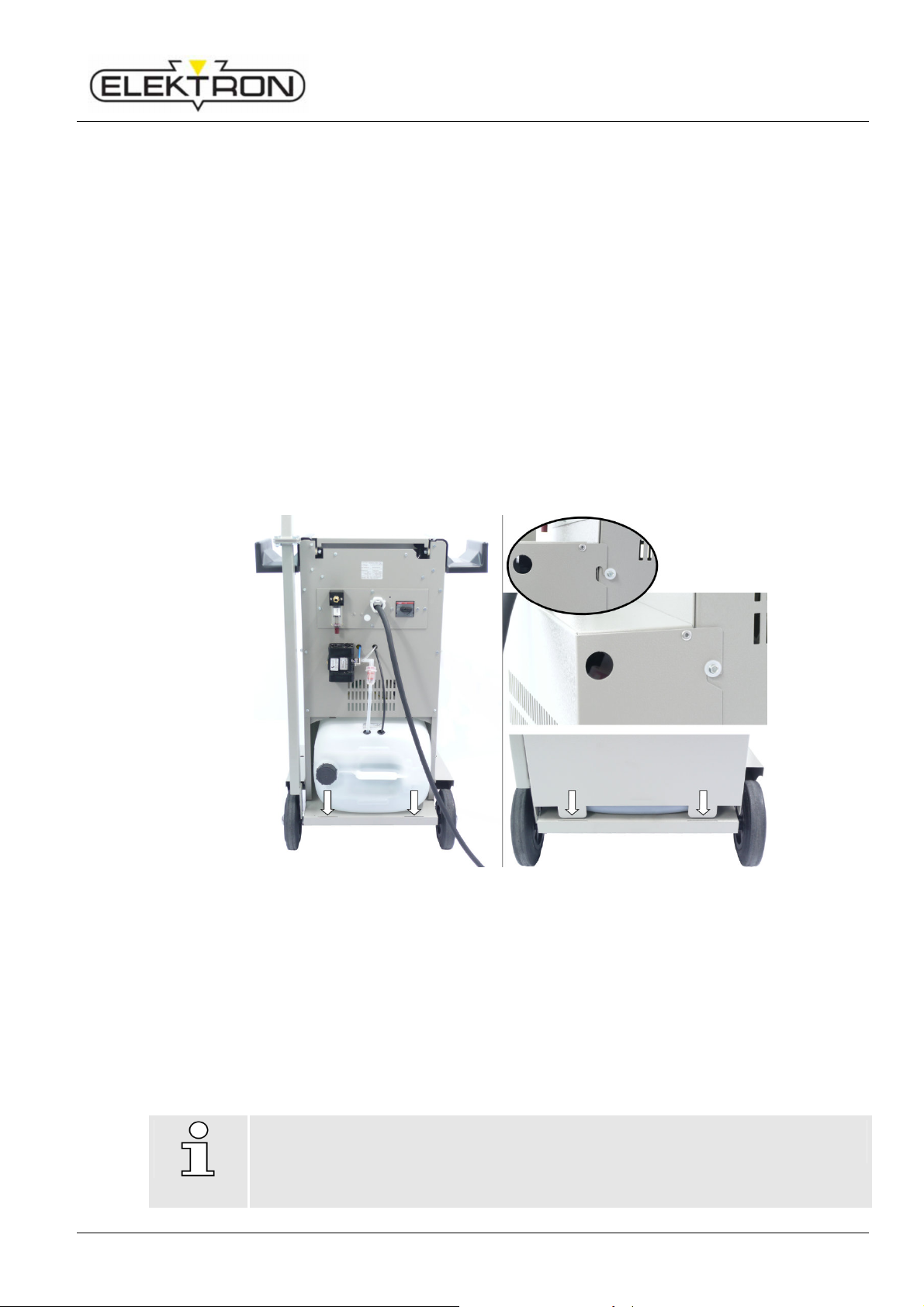
5.2 Filling up cooling water tank
Installation
Fig. 20: Filling up the cooling water tank
Remove the cover on the rear side, the coolant outlet and coolants return.
2. Remove cooling water tank raise and turn off cooling water tank cap.
3. Fill about 30 litres / 7.9 gallons of cold, clean drinking water into the tank.
4. Add chlorine-free disinfectant to prevent growth of algae and bacteria.
5. Replace cap properly. Check for tightness.
6. Move the cooling water tank back. Put in the coolant outlet and coolant return into the tank; put on
the rear cover.
7. Before you switch on the welder, check the coolant level before each use and, if necessary, top up
coolant.
NOTE!
For draining the tank, see “8.2.4”
31
Page 32
Resistance welder MULTISPOT MI-100control
CAUTION!
Property damage due to heat build!
Installation
5.3 Venting coolant circuit
The power unit of the MULTISPOT MI-100control is partially connected to the cooling
circuit.
Therefore:
Before initial operation and after each filling of the coolant tank, the cooling circuit
must be vented.
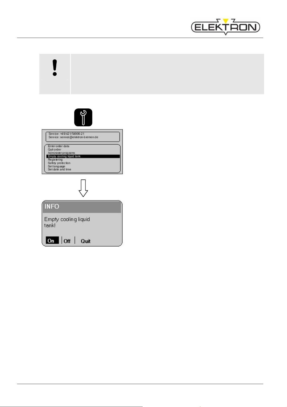
1. Press service button on the control panel – once.
This will call up the “Service” menu (page 1).
2. Use the control knob to select “Empty cooling liquid
tank”. Press to confirm.
Fig. 21: Draining the cooling system
3. To vent select “ON” and confirm.
———— To stop, select “OFF” and confirm.
———— To go back to the menu, select “Cancel” and confirm.
4. To vent the cooling water pump leave running until the
pump frequency audible significantly reduced.
32
Page 33
Resistance welder MULTISPOT MI-100control
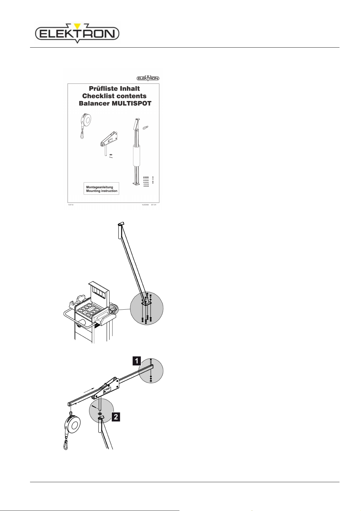
5.4 Assembling the balancer
Fig. 22: Balancer checklist
Installation
1. Unpack the balancer.
2. Check balancer components for damage. Use the
checklist provided (Fig. 22) to check whether you have all
the parts.
———— Balancer
———— Guide rollers with locking pin and ring
———— Vertical pipe and crossbar pipe
———— Replacement carabine hook
———— Four M8 bolts with two nuts and washers each
———— Mounting instructions
Fig. 23: Vertical pipe
Fig. 24: Crossbar pipe
3. Mount the vertical pipe using four M8 bolts
(Fig. 23, see separate operating and mounting
instructions).
4. Mount the crossbar (Fig. 24,
see separate mounting instructions).
Proceed as follows:
———— Mount and screw down stopper (Fig. 24/1).
———— Insert crossbar pipe into guiding element.
Secure with locking pin (Fig. 24/2).
———— Hang up spring balancer and secure (see operating
instructions for spring balancer).
33
Page 34
Resistance welder MULTISPOT MI-100control
CAUTION!
WARNING!
Stumbling hazards
!
Installation
5.5 Electrical connections
Fig. 25: Power grid specifications
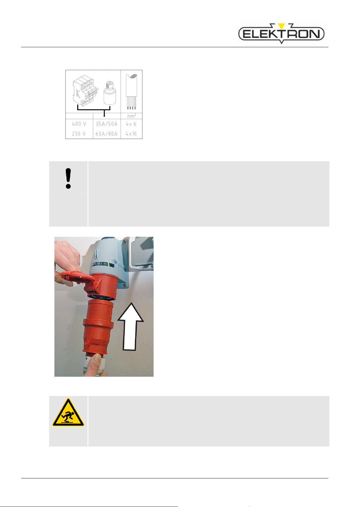
Insufficient conductor cross-sections and fuse protection may make the grid collapse
and / or trigger the fuses and make efficient welding impossible.
Therefore:
Before you connect the welder to the mains, make sure conductor cross-sections
are sufficient (at least 6 mm² per 10 metres / AWG 10 per 33 ft of cable length).
Before you connect the welder to the mains, make sure the grid is properly
protected by fuses (at 32 A).
Fig. 26: Connecting welder to power supply
1. Take the power cord from its support.
2. Run the power cord along a safe route.
3. Connect the power cord to the mains.
4. Use strain relief clamps to protect cables.
34
Power cords may constitute a stumbling hazard when improperly laid or installed and
may cause people to fall and hurt themselves. In this particular case, the cable could
block the wheels of the welder and make it tip over.
Therefore:
Run the power cord along a safe route.
Page 35
Resistance welder MULTISPOT MI-100control
CAUTION!
Improper pressure of com
pressed air may damage property!
5.6 Connecting the pneumatics
Fig. 27: Connecting compressed-air supply
NOTE!
6 bar (87 Psi) input pressure generate a contact force of the electrodes of 360 daN
(809 lb f) approx.
To adjust the contact force of the electrodes, proceed as described below.
Installation
1. Take the supply line from the pneumatic grid of the plant
and plug it on to the welder (Fig. 27).
2. The plant’s pneumatic mains must provide about 8 bar
(116 Psi) input pressure to the welder.
Fig. 28: Pressure gauge and pressure regulator
3. Check the pressure supplied at the pressure gauge
(Fig. 28).
If necessary, use the pressure regulator (Fig. 28) to set
the pressure as required (depending on welding program
and manufacturer’s specs).
Turn the regulator in the “+” direction to increase the
input pressure.
(max. admissible: 10 bar / 145 Psi)
Turn the regulator in the “–” direction to decrease the
input pressure.
(min. admissible: 6 bar / 87 Psi)
4. When decreasing the input pressure, actuate the pliers
from time to time to let the air escape.
5. Push in the regulator to set and lock the selected value.
Low pressure reduces the contact force of the electrodes which, in turn, increases wear
of the electrodes. High pressure, on the other hand, may damage the spot welding
pliers.
Therefore:
Check the pressure gauge before you switch on the welder. Compare to the
parameters of the welding program selected.
Maintain the pressure between 6 and 10 bar (87 and 145 Psi).
35
Page 36

Resistance welder MULTISPOT MI-100control
Installation
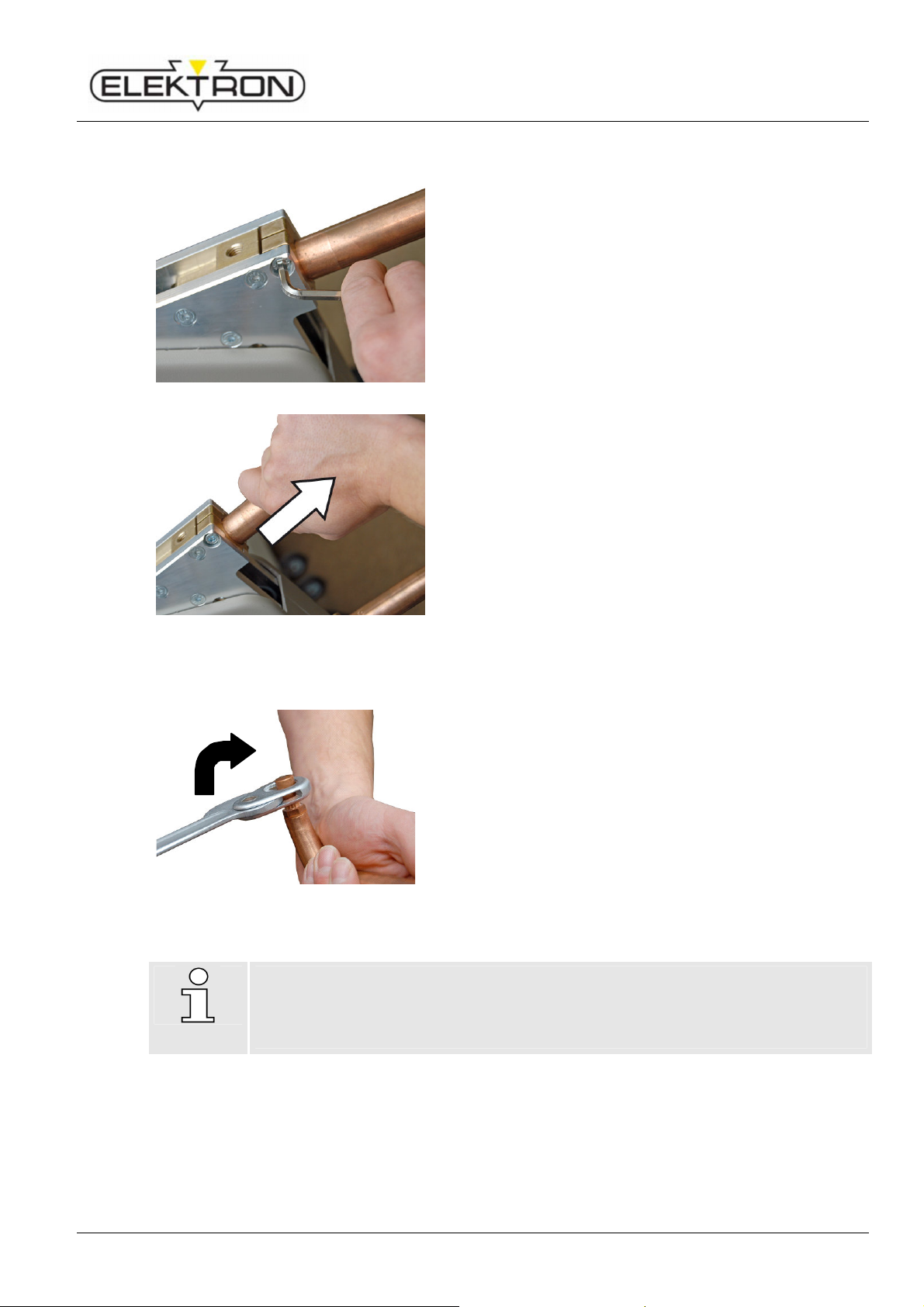
5.7 Connecting the pliers
1.
2.
Fig. 29: Connecting the pliers
1. Push the main plug of the welding pliers into the main
socket of the equipment (Fig. 29/1.).
2. Turn the retainer nut clockwise (Fig. 29/2.) to lock the
connection.
Fig. 30: Water cooling system for the pliers
Fig. 31: Connecting sensors of the pliers
3. Connect the water cooling system of the pliers.
4. Connect the sensors of the pliers.
36
Page 37

Resistance welder MULTISPOT MI-100control
Attention!
5.8 Connecting the welding gun
1.
2.
Fig. 32. Connecting the gun
Installation
1. Push the main plug of the welding pliers into the main
socket of the equipment (Fig. 32/1.).
2. Turn the retainer nut clockwise (Fig. 32/2.) to lock the
connection.
3. Unit will switch automatically and shows the “gun” symbol
in the display.
4. Connect the copper shoe of the grounding cable to a bare
point on the bodywork to be welded. Use lever clamp
provided or a mole wrench.
Before using the lever clamp, you have to weld on
two 8 mm washers as close to the point of weld as
possible, (see 6.9.2)!
In this case, press the copper shoe of the grounding
cable firmly onto the metal sheet. This is the only way
to obtain a good current transfer.
Fig. 33: Copper shoe and lever clamp
The copper shoe must always be connected to the metal sheet below the metal part of
the body to be worked on.
In any case avoid current transfer via hinges, door and bonnet locks, as these might
otherwise be damaged! (see 6.9)
37
Page 38

Resistance welder MULTISPOT MI-100control
WARNING!
Do no
t hurt yourself during grinding!
WARNING!
Unintentional
start
-up
of welder may
constitute a hazard of injuries!
CAUTION!
Operation
6 Operation
6.1 Preliminary works before welding
6.1.1 Preparing the sheets
Always connect the earth connection to the lower sheet. Otherwise the electricity cannot
flow.
When using insulating layers (e.g. spot welding primer), you must first establish an auxiliary
connection (using a vise-grip wrench, for instance) in order to establish the electrical contact.
Contact faces must be ground down to the bare metal on all sides.
Grinding sheets may constitute a hazard of injuries.
Therefore:
Be sure to deploy employees who are experienced in this type of jobs.
Strictly observe any manuals etc. that come with the grinding tools.
Galvanised sheets should not be damaged, if possible.
Make sure the sheets are always stacked with their faces parallel to each other.
Otherwise, it will not be possible to apply clean spot welds.
6.1.2 Preparing welding pliers
If the new tool is switched on during retooling, the weld current and / or unintentional
movements of the pliers may be actuated. There is a danger of pinching and crushing.
Therefore:
Be sure to tool up first, and only then switch on the welder.
If retooling is unavoidable during the work, be sure to switch OFF before you do
anything.
NOTE!
For more detailed information on preparing / tooling up the welding pliers,
see separate operating instructions.
Therefore:
Switch off cooling first before changing electrodes!
38
Page 39
Resistance welder MULTISPOT MI-100control
Operation
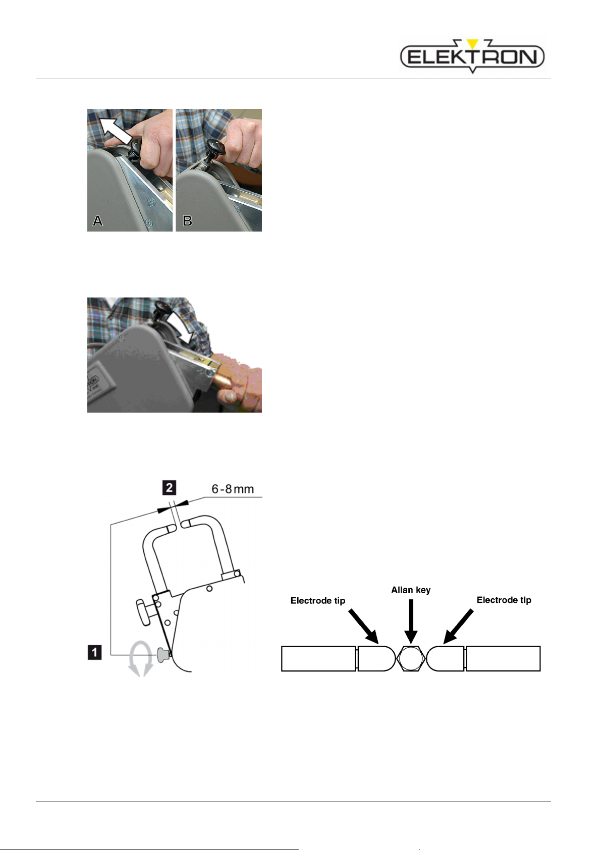
Exchanging electrode arms
1. To unbolt the electrode arm, use the Allen key provided
for that purpose (Fig. 34).
Fig. 34: Unbolting electrode arm
2. Remove the electrode arm simply by pulling it out.
(Fig. 35).
3. Insert the new electrode arm and bolt down.
Fig. 35: Removing the electrode arm
Exchanging electrode caps
Fig. 36: Exchanging electrode caps
NOTE!
The perfectly sound condition of the caps is essential for good welding results.
Electrode caps must be milled (or replaced) latest after 50 welding jobs, especially
when working with super speed and / or galvanised steel.
1. To loosen the electrode caps, use the special key
provided for that purpose (or some equivalent tool)
(Fig. 36).
2. Turn clockwise, otherwise the cone comes loose.
3. Put the new caps on the electrode head and press in
position.
39
Page 40
Resistance welder MULTISPOT MI-100control
Operation
Deploying the electrode arm
Fig. 37: Unlocking the arm / hoop
Locking the electrode arm
1. Switch the locking device of the electrode arm / hoop from
position “locked” (Fig. 37/A) to position “open” (Fig. 37/B)
as shown in the picture.
2. Push the electrode arm / hoop without much force into the
Fig. 38: Locking the arm / hoop
Adjusting the distance between electrodes
Make sure the distance between the electrodes is 6 to
Carry out the first welds, and then check the distance
Use an Allen key SW 5 as gauge in between the tips:
locking device until you feel and hear it engage (Fig. 38).
8 mm.
again. Re-adjust, if necessary.
Fig. 39: Adjusting the distance between
electrodes
Fig. 40: Measure the distance between electrode tips
40
Page 41
Resistance welder MULTISPOT MI-100control
WARNING!
Unskilled
employees may hurt themselves and others. Inexpert
Aligning electrodes
Fig. 41: “Electrode must be in true alignment”
Additional explanation on the welding plier, see separate operating manual.
6.1.3 Checks before switching on
Inexpert and / or negligent handling of this equipment and / or ignorance of hazards and
dangers may entail the most severe injuries.
Therefore:
Make sure this equipment is put to use by skilled welding operators with sufficient
training and experience in spot welding, exclusively.
Before operation, consult the manual and make sure any and all preconditions are
fulfilled; any and all checks and preliminary works etc. have been carried out.
Work place must be clean and tidy – no clutter. Make sure you have enough room
to move.
Operation
Be sure to look from different angles. Electrodes must
align no matter how you look.
operation constitutes a hazard of injuries!
Be sure to be wearing adequate PPE. ( see “2.2.3”.)
Check any and all connections. ( see “5”.)
Check input pressure. ( see “5.6”.)
Check cooling water level. ( see “5.2”.)
Check your tools / welding pliers). Re-tool now, if necessary.
( see “6.1.2” and / or separate operating instructions for welding pliers.)
Check status of the emergency stop pushbutton. ( see “2.6”.)
If you find the emergency stop button locked, check the welder and make sure it is
operational before you unlock the pushbutton. Turn clockwise (cw) to unlock.
41
Page 42

Resistance welder MULTISPOT MI-100control
3
.
Operation
6.2 Switching on
Fig. 42: Power switch
1. Once the welder has been installed and prepared
according to instructions, you may switch it on by turning
the power switch (Fig. 42).
If switching on has been successful, the display will show the
following message: S07 “Powering up, please wait.”
This will be followed by the message shown here on the left
(Fig. 43).
Fig. 43: Prompting operator to service caps
Fig. 44: Control knob
2. Visually check caps.
Clean, mill and / or replace the electrode caps, as
required.
Turn the control knob (Fig. 44) clockwise (cw) to position
“OK”. Confirm by pressing.
The display shows:
S12 “Calibrate tool”
“Please weld without sheets”
4. Press the welding button on the welding pliers.
If calibration was successful, the display will show:
S13 “Calibration successful”
> “OK”
5. Acknowledge by pressing the control knob.
If calibration was not successful, the display will show:
S13 “Error at calibration”
> “Repeat / Abort”
The reason may be that the electrode caps are dirty or worn.
If that should be the case, clean the electrode caps again.
If necessary, mill or replace. ( see “6.1.2”).
Repeat calibration.
42
Page 43
Resistance welder MULTISPOT MI-100control
6.3 Basic settings
6.3.1 Set languages
To set the display language, proceed as follows:
Operation
1. Switch off the welder.
2. Pull the plug of the welding pliers.
3. Switch on again.
The display will show message “F35”.
4. Acknowledge by pressing the control knob.
5. Press the service button (wrench icon).
6. Use the control knob to select menu item
“Set languages” (Fig. 45). Confirm.
Fig. 45: Service menu (page 1)
Fig. 46: Languages menu
Next, the display will show a list of languages from which to
choose (Fig. 46).
7. Use the control knob to select a language. Confirm.
43
Page 44

Resistance welder MULTISPOT MI-100control
Operation
6.3.2 Register welder
Fig. 47: Menu item „Registering”
Fig. 48: Registering the welder
Menu item “Registering” displays the equipment info.
The equipment may be registered.
Registering is required, if you want to use the “Free mode”
and “Program mode”.
1. Use the control knob to select menu item “Registering”.
Confirm.
The display shows the equipment info (Fig. 48).
2. Write down equipment ID and software version.
3. Go to the ELEKTRON website: www.elektronbremen.de.
Call up the “Product registration” page. Enter your data.
4. Fill in all the information in the online form in order to
obtain the best possible service.
As soon as we have received your registration data, we send
you an email with your registration number.
NOTE!
Make sure your data is correct. Otherwise, your welder will not be cleared.
Registration must be carried out within 120 days after delivery.
5. Enter the registration no. in menu item “Registering” of
the service menu.
44
Page 45

Resistance welder MULTISPOT MI-100control
CAUTION!
Improper settin
gs may
lead to improper welding!
1.
6.4 Recurring settings
6.4.1 Maintaining electrode caps
Fig. 49: Prompting operator to service caps
6.4.2 Selecting control mode
Failure to properly set the risk of faulty welds.
Therefore:
Welding parameters in the “Free mode” must be set by skilled welding operators,
exclusively.
Operation
Whenever you switch on the welder and in regular intervals
during operation, you will be reminded to take care of the
electrode caps (Fig. 49).
What to do:
1. Check the caps. If necessary, clean, mill or replace the
caps.
2. Only then confirm by switching control knob to “OK”.
Fig. 50: Main menu
Press the control knob twice, quickly.
2. Use the control knob to select one of the three following
control modes.
“Keyboard operation”
For the welding job at hand, the following parameters
may be set manually;
see “6.4.2.2”.
“OEM programs“
To select programs provided by the OEMs;
see “6.4.2.3”.
“Free mode”
This mode is suitable for skilled operators who have
experience in setting welding program parameters and
know exactly about their effects and consequences;
see “6.4.2.4”.
NOTE!
If the OEM provided a welding program, operate the welder in mode “Prg. Selection”.
45
Page 46

Resistance welder MULTISPOT MI-100control
Operation
6.4.2.1 Keyboard operation
Keyboard
Program selectio
Free mode
Fig. 51: Selecting the control mode
1 Selecting welding gun,
active only if a welding gun has
been installed.
2 Selecting sheet gauge,
weld current and time will be
calculated and displayed.
3 Selecting material combination,
weld current and time will be
calculated and displayed.
4 Manual selection of weld current,
If weld current is changed
manually, the weld time will be
adjusted automatically.
For the welding job at hand, the following parameters may be
set manually:
Tool
Sheet gauge
3
Material, number of sheets , description
Weld current
Fig. 52: Touch keys on control panel
46
Page 47

Resistance welder MULTISPOT MI-100control
1.
Sheet gauges up to
about
6.4.2.2 Setting welder in mode “Keyboard operation”
Use the control knob to select mode
“Program selection”. Confirm.
2. Use a calliper gauge to measure the sheet gauges for the
welding job at hand.
Keyboard
Program selectio
Free mode
Fig. 53: Selecting the control mode
3. Determine the pertinent gauges for the job using the
3
following table.
4. Using the following table, determine the set value
required. Use the touch keys (Fig. 53) to enter the set
value.
Welding job Ratio of sheets
0,8 + 0,8 + 0,8
1,0 + 1,0 + 1,0
d1 = d2 = d3
Operation
Set value Selection
d2 ≈ d3
d1 < d2 < d3
1,5 + 1,5 + 1,5
2,0 + 2,0 + 2,0
2,0 + 0,8 + 0,8
0,8 + 1,0 +1,0
0,8 + 1,5 + 1,5
0,8 + 2,0 + 2,0
0,8 + 3,0 + 3,0
d1 + d2 + d3 ≤ 3
Select next higher
set value.
(*) optionally ON or OFF
(!) “3 sheets” OFF
47
Page 48
Resistance welder MULTISPOT MI-100control
1
Operation
6.4.2.3 OEM programs
This mode contains a number of pre-set programs provided
by OEMs.
Keyboard
Program selectio
Free mode
Fig. 54: Selecting the control mode
Fig. 55: Overview of OEM programs
Tools required
2 Electrode caps required for welding
program
3 No. of pulses (1 – 36)
4 Weld current required
5 Weld time required
(Total of all current times)
6 Contact force required
7 Program name or
8 Control mode
(depending on selection)
9 Required length of electrodes
1. Use the control knob to select mode
“Program selection”. Confirm.
Next, the display will show a list of available welding
programs (Fig. 55).
2. Use the control knob to select a program. Confirm.
Next, you will see the parameters of the program selected
(Fig. 56).
Fig. 56: Program parameters
48
Page 49

Resistance welder MULTISPOT MI-100control
6.4.2.4 Free mode
Keyboard
Program selectio
Free mode
Fig. 57: Selecting the control mode
Operation
This mode allows the welder to enter weld currents and times
manually, and to store them as own programs.
1. Use the control knob to select the mode “Free mode”.
Confirm.
NOTE!
The “Free mode” is suitable only for welding operators who have detailed knowledge of
welding parameters and their effects and interactions. The “Free mode” entails a high
risk of improper welding jobs.
Fig. 58: Prompting for password
NOTE!
It is incumbent upon the operating company to decide whether passwords should be
used and who should have a password or not.
Make passwords inaccessible to strangers.
Fig. 59: Dialogue box
The display shows a prompt requiring a password (Fig. 58).
2. Use the control knob to select “OK”. Confirm.
You will see the following prompt (Fig. 59):
“Take over current parameters or load program”
3. Use the control knob to select “Take over”. Confirm.
or
4. To modify an existing own program, select “Load”.
The display shows a list of all owns programs that have
been generated so far.
5. Use the control knob to select the program you want to
modify.
49
Page 50
Resistance welder MULTISPOT MI-100control
1.
1.
Operation
Actual values
Folie MX
MX4900 AØB4CØD4
Fig. 60: Parameters
Modifying welding current (kA)
Actual values
Folie MX
MX4900 AØB4CØD4
Fig. 61: Parameters
Next, you will see a list of the current parameters in the
display (Fig. 60).
Press control knob.
2. Use the control knob to select “kA”. Confirm.
The current value (kA) will be highlighted in black.
3. Use the control knob to adjust the welding current value
(kA):
Turn clockwise to increase the value.
Turn counter clockwise to decrease the value.
4. Press control knob to confirm.
5. Press “Esc” to cancel and go back to the main menu.
Modifying welding time (ms)
Press control knob.
2. Use the control knob to select “ms”. Confirm.
The time value (ms) will be highlighted in black.
3. Use the control knob to adjust the welding time value
Actual values
Folie MX
MX4900 AØB4CØD4
Fig. 62: Parameters
(ms):
Turn clockwise to increase the value.
Turn counter clockwise to decrease the value.
4. Press control knob to confirm.
5. Press “Esc” to cancel and go back to the main menu.
Storing own programs generated in “Free mode”
Own programs generated individually may be stored under
any name, together with a short description.
50
Free mode
Fig. 63: Selecting „Free mode”
Proceed as follows:
1. Press control knob.
The box “Free mode” will be highlighted in black (Fig. 63).
Page 51

Resistance welder MULTISPOT MI-100control
Operation
2. Press control knob again.
You will see the following prompt: “Want to store
changed program?” (Fig. 64).
3. Use the control knob to select “Store”. Confirm.
Fig. 64: Dialogue prompting to store or reject
A B C D E F G H I J K
L M N O P Q R S T U V
W X Y Z . , +
0 1 2 3 4 5 6 7 8 9 ::::
;
; # % ! " @ ( ) < = >
; ;
OK
OK
OKOK
. , + ----
. , + . , +
DEL
Program name:
••••
/
- - - - - - - - - - - - - - - - - - -
Program info :
- - - - - - - - - - - - - - - - - - -
- - - - - - - - - - - - - - - - - - -
- - - - - - - - - - - - - - - - - - -
- - - - - - - - - - - - - - - - - - -
In the following dialogue box, enter a Program name and
Program info, if required.
4. Use the control knob to enter and confirm the characters
you need to write the text.
5. When finished, select “OK”. Confirm.
The new program has now been stored in the folder
Fig. 65: Entering program name and info
“Individual programs”.
Fig. 66: Main menu
6.4.3 Electrode recognition
6. To continue, press the control knob.
The display takes you back to the main menu.
The MULTISPOT MI-100control and the electrode arms are
equipped with an automatic electrode recognition system.
Electrodes are being identified automatically, and the length is
shown on the display.
If the automatic electrode recognition is off or does not work,
(Fig. 67), the length of the electrodes must be entered
manually. Proceed as follows:
There will be an error message. Acknowledge using the
Fig. 67: No electrode recognition
control knob.
51
Page 52
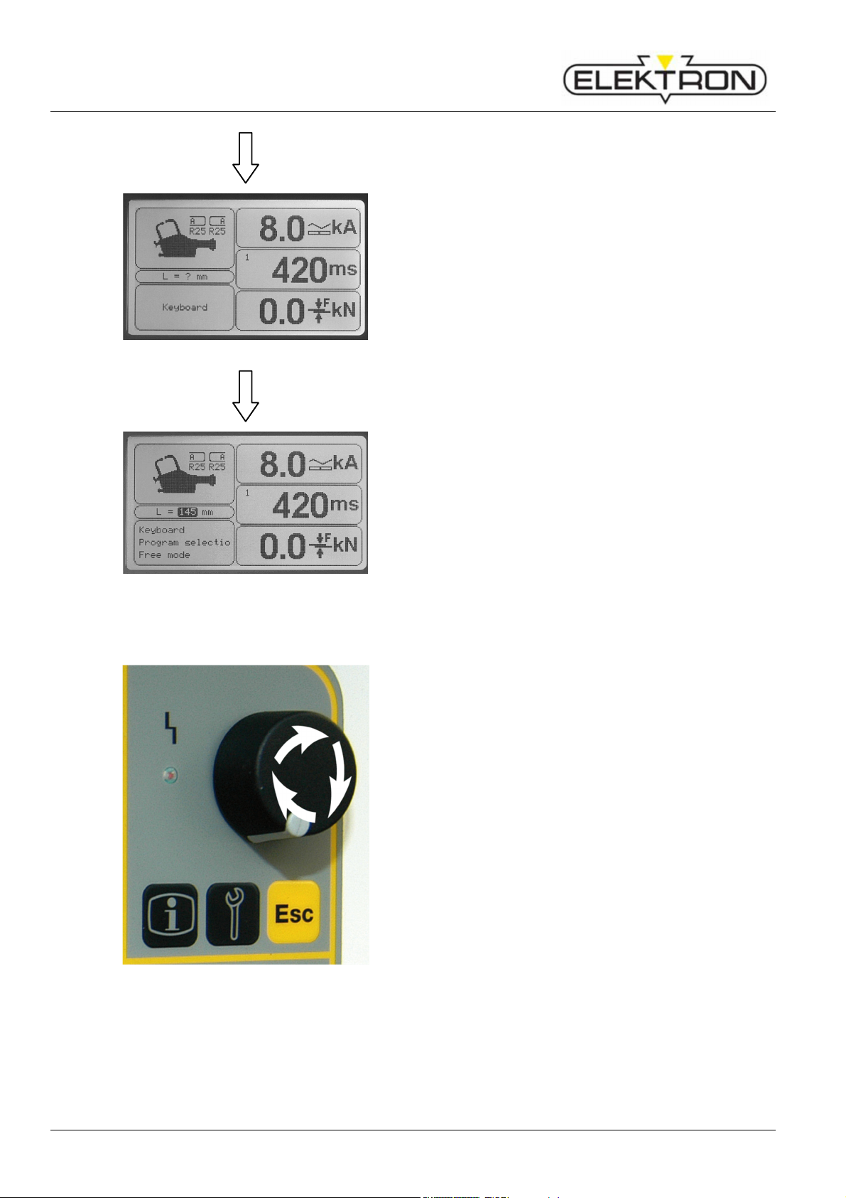
Resistance welder MULTISPOT MI-100control
Operation
Fig. 68: After acknowledgement
The length of the electrodes will be displayed with a question
mark. The contact force will be “0.0” (Fig. 68).
Setting the electrode length manually:
Fig. 69: Correct display of electrode length
6.4.4 Manual tool selection
Fig. 70: Control knob
1. Press the control knob to get into the enter mode.
2. Now, turn the knob to select the length.
3. Press control knob to confirm.
The display shows the new value for the electrode length
(Fig. 69).
In case of emergency and / or for service purposes, it is
possible to switch off the automatic tool recognition system
and select the tool installed manually on the control panel.
Proceed as follows:
1. Switch off the welder.
2. Install the tool on the welder.
3. When you switch on the welder again, press the start
button of the tool. The tool box of the display will contain a
question mark now.
4. Press the control knob once.
5. Turn the control knob to select the tool box. The tool box
will be highlighted in black.
6. Press control knob.
7. Use the control knob to select the desired tool. Confirm.
There will be a reset whenever you exchange tools and / or
switch off the welder.
52
Page 53

Resistance welder MULTISPOT MI-100control
CAUTION!
Build
-up
of heat may cause damage to property.
DANGER!
Electromagnetic fields pose a potentially fatal hazard to people with
6.4.5 Switching off the cooling water pump
Fig. 71: Message S09
Operation
You may stop the cooling water pump and weld current at any
time. Just press “Esc”.
(E. g. to change the electrodes).
After the pump has stopped, the display will shows the
message “S09“ (Fig. 71).
If the cooling water pump is switched off at the end of a welding job, heat may build up
and entail damage to property.
Therefore:
Allow the pump to go on for at least 10 mins. After you have finished a job.
6.5 Important information concerning welding
Electromagnetic fields
pacemakers or other magnetisable implants.
Electromagnetic fields affect the functionality of pacemakers and other magnetisable
implants. Electromagnetic fields can irritate human sense organs, nerve and muscle
cells.
Therefore:
Persons with pacemakers or other magnetisable implants must not approach the
working area.
Be sure to put up suitable warning signs.
Be sure to put warning signs on access ways and doors leading to the work area.
Do not guide welding cables along people’s heads or spines. Keep a distance of at
least 2 cm.
53
Page 54

Resistance welder MULTISPOT MI-100control
WARNING!
Splashes and flying sparks constitute a danger of fire and
WARNING!
Vapours may con
stitute a danger to your health!
CAUTION!
Hot surfaces pose a risk of burns!
CAUTION!
Tipping and toppling may cause damage
to property!
Operation
Splashes, flying sparks
explosion. Splashes and flying sparks pose a risk of injuries!
Welding generates sparks and –hot spatter. They can ignite combustible materials and
generate explosions. Contact with body parts may entail injuries.
Therefore:
Before you tackle any welding jobs, make sure there are no combustible and / or
explosive materials in the work area.
Do not carry out welding jobs in the vicinity of pressure vessels, tanks, oil barrels,
paint cans and / or in a work area with an explosive atmosphere.
Have fire extinguishing gear ready at hand.
Make sure access and escape routes are not blocked.
During any and all welding jobs: be sure to be wearing a face screen, non-
inflammable safety clothing and welder’s gloves.
Do not carry easily inflammable objects in your pockets (matches, lighters etc.).
Vapours
Stock that has not been properly ground and cleaned before welding may be
contaminated with residues of glues, paints, undercoating products etc. that may
generate harmful or even toxic vapours during welding.
Therefore:
Before you tackle any welding jobs, make sure the sheets you want to weld have
been properly ground and cleaned and are free of residues.
Be sure to be wearing a face screen. Respiratory equipment may be
recommendable in case of doubt.
Hot surfaces
Electrodes may heat up to 80 degrees centigrade approx. Stock may have up to 100
degrees right after welding. So there is an acute risk of burning yourself.
Therefore:
Never work without proper safety clothes and gloves near hot components.
Let freshly welded parts cool down to ambient temperature before you go on to
work with them.
Tipping and toppling hazards due to high centre of gravity and obstacles during travel
This equipment’s centre of gravity is relatively high. In the event the wheels jam and / or
block (due to an obstacle or transverse pull, for instance), there is a danger the
equipment tips over.
Therefore:
Move this equipment always using the handles.
Keep potential obstacles out of the work area.
Install cables and supply lines in such a way that they do not constitute a stumbling
trap.
54
Page 55
Resistance welder MULTISPOT MI-100control
CAUTION!
Equipment rolling aw
ay may cause damage to property!
S
afety clothing
Safety shoes
Face screen
Welder's
gloves
Furthermore
Operation
There is a danger the equipment rolls away because the wheels must not be blocked due to the
tipping and toppling hazard
The wheels of the equipment must not be blocked because this would cause a tipping
and toppling hazard. On the other side, though, this detail causes and increases the
danger the equipment rolls away.
Therefore:
Be sure to operate this equipment only on a flat and even floor.
Proceed with care when moving this equipment.
Personal protective equipment (PPE)
When working, always wear:
…is a tight-fitting sort of special clothing that is not inflammable, covers arms and legs
completely and tears easily (instead of getting pulled in).
Its main purpose is to protect against burns.
…protect the wearer's feet against falling objects, slippery surfaces and being run over
by vehicles.
For special works wear:
…protects the face and eyes against splashes, flying sparks and other hot particles.
…protect the hands against splashes, flying sparks and other hot particles, and prevent
contact with hot surfaces.
Never use wet welder's gloves.
…no long hair, rings, necklaces, watches and / or other sorts of jewellery. Do not carry
easily inflammable objects in your pockets (matches, lighters etc.).
Be sure to be always wearing the appropriate PPE for the job at hand.
Be sure to take note of and comply with warning signs concerning PPE that may be installed
at the workplace.
55
Page 56

Resistance welder MULTISPOT MI-100control
CAUTION!
Danger to property
!
Operation
Adjusting the contact force
NOTE!
Be sure to set the correct contact force with respect to the current welding / OEM
program selected – because:
If the contact force of the electrodes is too high, the electrical resistance will be too
weak which, in turn, will affect the welding job.
If the contact force is too weak, the welding spots may erode and leave holes in the
sheets.
Fig. 72: Contact force ≤ 240 daN
When using the electrode arm configuration shown to the left, 12-mm electrodes will
slightly bend if the contact force is set higher than 240 daN (540 lb f).
Therefore:
Ask yourself, whether the job at hand could be handled just as well with a different
configuration.
When you have to use the configuration as shown here, make sure the contact
force does not exceed 240 daN (540 lb f) / 4.6 bar (67 Psi).
Distances between welding spots
Fig. 73: „Distances should not be too short.”
Lifetimes of electrode caps
Don’t keep the distances between welding spots too
short (25 mm approx.). Otherwise, the weld current
might affect the spots (that have already been applied)
a second time.
56
NOTE!
The perfectly sound condition of the caps is essential for good welding results.
Electrode caps must be milled (or replaced) after 50 welding jobs, especially when
working with high strength and / or galvanised steel ( see “6.1.2”).
Page 57

Resistance welder MULTISPOT MI-100control
6.6 Calling up welding parameters
Actual values
Folie MX
MX4900 AØB4CØD4
Fig. 74: Displaying main welding parameters
Operation
Press Info button once.
This will call up the current values of the most important
welding parameters for the last welding job (Fig. 74):
Weld current
Weld time
Contact force (electrodes)
Press Info button twice.
Fig. 75: Displaying all parameters
6.7 Settings in the service menu
NOTE!
The access and edit rights of some of the menus depend on the settings defined in
ELEKTRON’s key file. If you should have any questions or need additional rights,
please contact us.
NOTE!
Any service settings not described in this manual must be handled by skilled service
personnel, exclusively. They do not have any influence on the functionality of the
welder.
This will call up all the welding parameters (Fig. 75).
57
Page 58
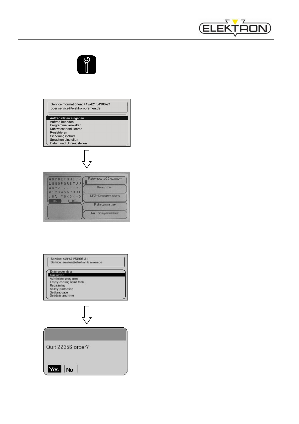
Resistance welder MULTISPOT MI-100control
Operation
6.7.1 Service menu settings (page 1)
6.7.1.1 Enter order data
Press service button on the control panel - once.
This will call up the “Service” menu (page 1).
Enter the order data under menu item “Enter order data”:
Use the control knob to select “Enter order data”. Press to
confirm.
Fig. 76: Categories of information
6.7.1.2 Concluding an order
Vehicle number
User ID
Vehicle licence number
Type of vehicle
Order number
If the control does not detect activities over 60 mins., the data
must be either 75 confirmed or modified.
Menu item “Quit order” is for concluding an order.
Use the control knob to select “Quit order”. Press to confirm.
As soon as “Yes” has been pressed, all welding data of the
order are stored and can be read and / or printed with the
program.
Fig. 77: Concluding an order
58
Page 59
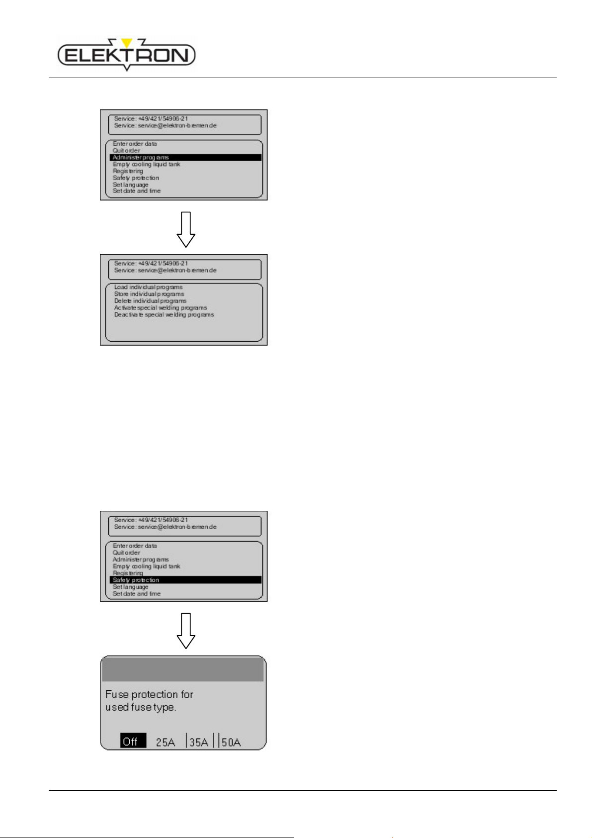
Resistance welder MULTISPOT MI-100control
6.7.1.3 Administering programs
Fig. 78: Administering programs
Operation
For organising and administering existing programs, use
menu item “Administer programs”. Proceed as follows:
Use the control knob to select “Administer programs”. Press
to confirm.
Loading individual programs from the CF memory card.
Storing individual programs for future transfer.
Deleting individual programs.
Activating special welding programs.
Deactivating special welding programs.
6.7.1.4 Emptying cooling system
see “8.2.3”
6.7.1.5 Registering welder
see “6.3.2”
6.7.1.6 Activating fuse protection
Menu item “Fuse protection” is for calling up a time delay
after welding in order to protect the fuses against overheating.
Fuse protection is off by default.
1. Use the control knob to select “Fuse protection”. Press
to confirm.
2. Select the fuse protection setting you need. Press to
confirm.
Fig. 79: Menu “Fuse protection”
59
Page 60

Resistance welder MULTISPOT MI-100control
Operation
6.7.1.7 Setting languages
see “6.3.1”
6.7.1.8 Setting time and date
Use menu item “Set date and time” to set the time and date.
1. Use the control button to select “Set date and time”.
Press to confirm.
Fig. 80: Setting time and date
6.7.2 Service menu: settings (page 2)
6.7.2.1 Calling up electrode-cap service mode
2. Use the control button to set the date and / or time. Press
to confirm.
Press service button on the control panel - twice.
This will call up the “Service” menu (page 2).
Use the menu item “Cap service mode” to manually call up
electrode cap cleaning.
In this mode, the power supply is cut off. Only the electrode
clamp system works.
Use the control knob to select “Cap service mode”. Press to
confirm.
60
Page 61

Resistance welder MULTISPOT MI-100control
Fig. 81: Cap service activated
6.7.2.2 Changing configuration
Operation
You will see the message shown here on the left.
Use the menu item “Change configuration” to carry out
changes to the configuration. You need appropriate access
rights.
In addition, you need an “Expert” CF memory card.
Fig. 82: Changing the configuration
6.7.2.3 Loading most recent configuration
If no “Expert” CF memory card has been slotted, you will see
the message shown here on the left.
With the menu item “Load last configuration”, you can
restore the most recent configuration used.
If the new configuration fails, the system will automatically
revert to the previous version.
Use the control knob to select “Load last configuration”.
Press to confirm.
61
Page 62
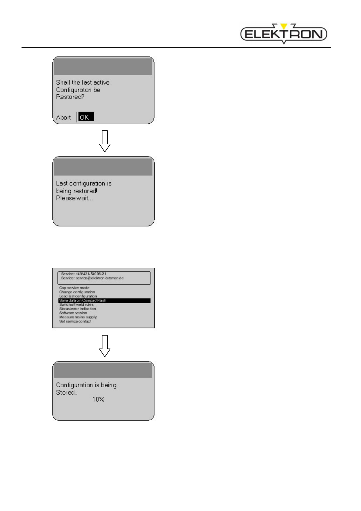
Resistance welder MULTISPOT MI-100control
Operation
You can simply acknowledge the next prompt by selecting
“OK”.
You will see the message shown here on the left.
Fig. 83: Loading last configuration
6.7.2.4 Storing all welding jobs
Use the menu item “Save data on compact flash” to store
data on the internal CF memory card.
The data can be later read and printed with special software
(traceability program).
Use the control knob to select “Save data on compact
flash”. Press to confirm.
You will see the message shown here on the left.
Fig. 84: Storing all welding jobs
62
Page 63
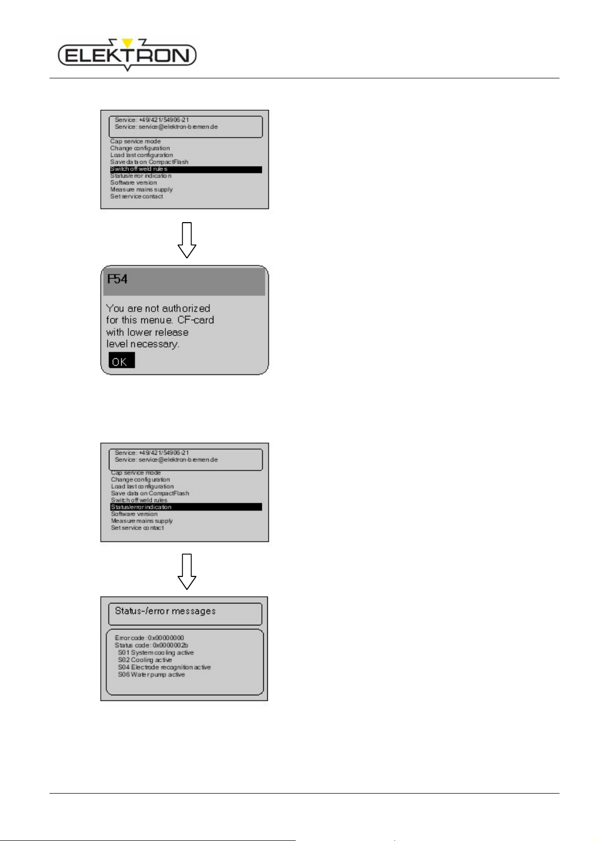
Resistance welder MULTISPOT MI-100control
Switch off weld rules
6.7.2.5 Switching off weld rules
Operation
Use the menu item “
weld rules that have been pre-defined and stored in the
system.
However, you need the “Expert” CF memory card to
accomplish this.
Use the control knob to select “Switch off weld rules”. Press
to confirm.
Depending on your access rights, you may receive, for
instance, the status message shown on the left.
” to switch off the
Fig. 85: Switching off weld rules
6.7.2.6 Calling up status and error messages
Use the menu item “Status / error messages” to display the
current software version(s) installed on the welder.
Use the control knob to select “Status / error messages”.
Press to confirm.
You will see the status and error message shown here on the
left.
Fig. 86: Calling up status and error messages
63
Page 64
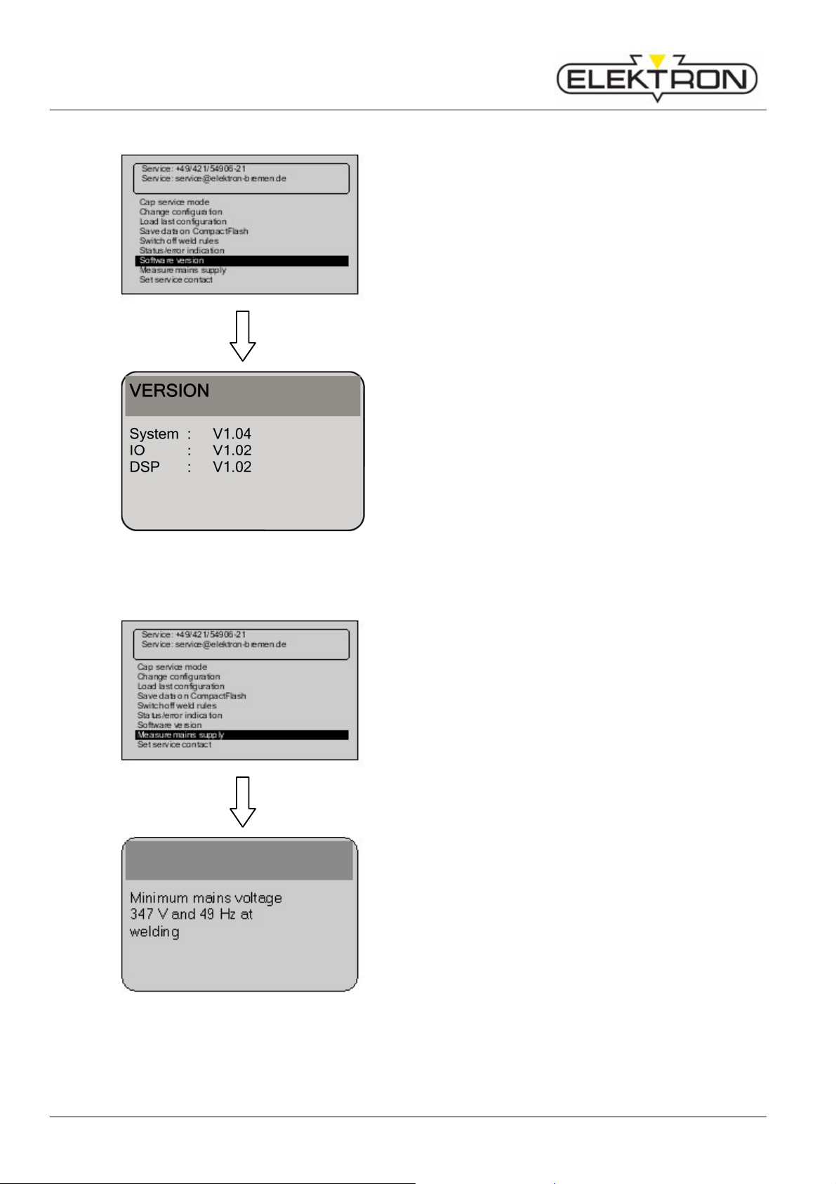
Resistance welder MULTISPOT MI-100control
Operation
6.7.2.7 Calling up the software version
Use the menu item “Software version” to display the current
version of the operating system.
You need the data for troubleshooting and for ordering wear
and spare parts.
Use the control knob to select “Software version”. Press to
confirm.
You will see the message shown here on the left.
Fig. 87: Software version
6.7.2.8 Calling up current and voltage values
Use the menu item “Measure mains supply” to display the
voltage drop.
You need the data for troubleshooting.
Use the control knob to select “Measure mains supply”.
Press to confirm.
You will see the data shown here on the left.
Fig. 88: Current and voltage
64
Page 65

Resistance welder MULTISPOT MI-100control
6.7.2.9 Modifying service address
Operation
Use the menu item “Set service contact” to modify the
service phone and email data displayed at the top of the
menu. Instead of the pre-set data, you may also set the
address of your local dealer.
1. Use the control knob to select “Set service contact”.
Press to confirm.
You will see the dialogue box shown here on the left.
2. If necessary, use the control knob to modify and confirm
contact data.
Fig. 89: Modifying service address
6.8 Updating software
ELEKTRON software option for spot welding equipment
CD-ROM + compact-flash memory card (CF memory card)
or
Update by email (You will need a compact flash memory card reader.)
Option: CD-ROM + CF card
The CD-ROM contains the documentation explaining the use of the OEM weld programs.
The documentation refers only to OEM weld programs and contains information on
programs to be used, electrode arms, welding positions and number of spots to be applied
on certain bodies. (Depends on OEM and may vary from type to type). The documentation is
in PDF format and can be read and printed using Adobe's Acrobat Reader.
The compact flash memory card contains all the program data concerning the X (MTX-4900)
and the C pliers (MTC-5000) you will need for an update.
Option: Update by email
We send you the update file by email. Before you start, you must copy and backup the “.elk”
file located on the CF memory card of the welder.
65
Page 66
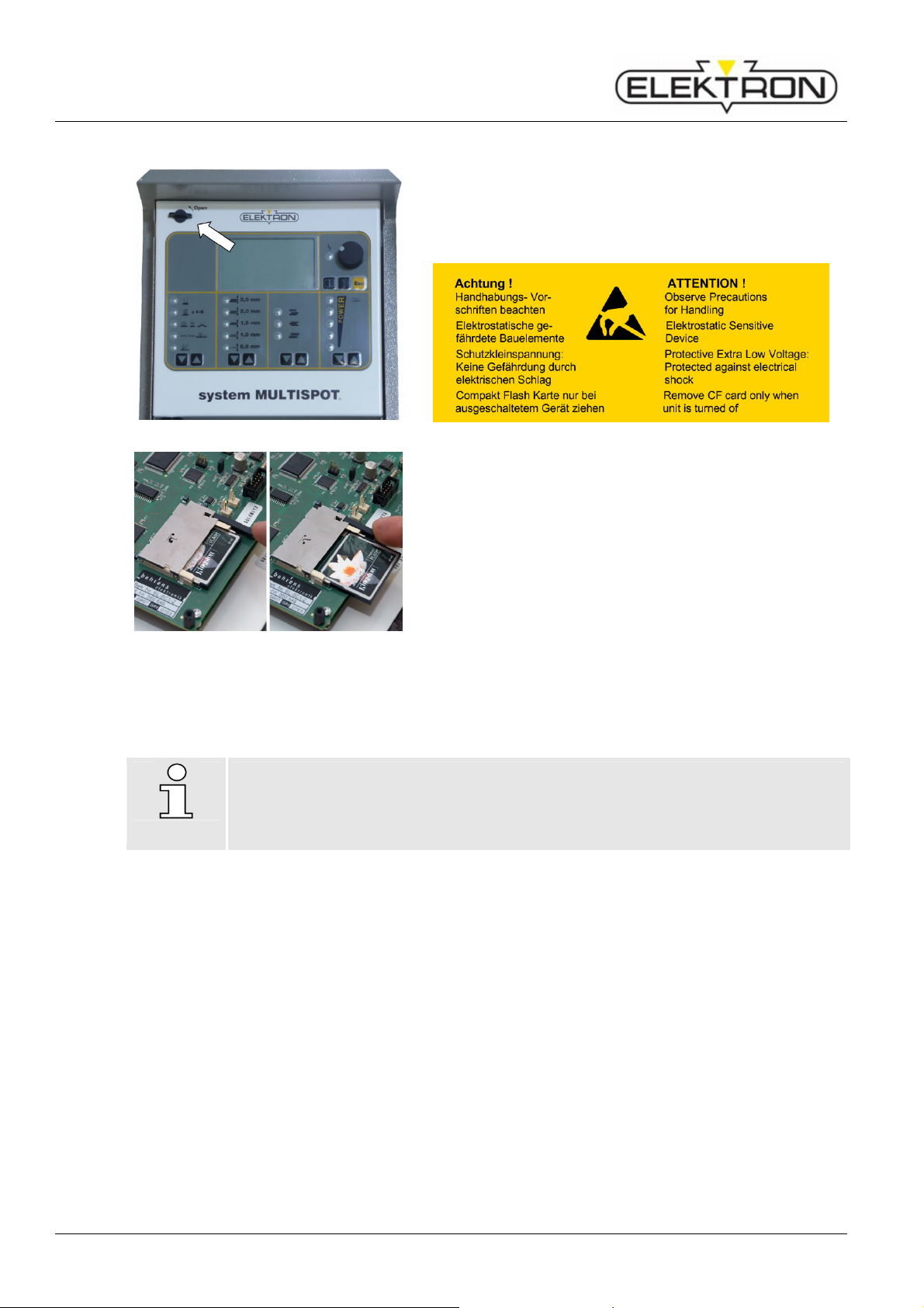
Resistance welder MULTISPOT MI-100control
4
.
Operation
Updating - proceed as follows
1. Switch off the welder.
2. Turn the knob on the left counter-clockwise (Fig. 90).
3. Swing out the control unit.
Fig. 90: Open the front panel
Fig. 91: Exchanging the CF memory card
NOTE!
Please check; if new registering is necessary ( see “6.3.2”). If it is not necessary, a
message will be shown after entering the menu item “Registering”.
Press the eject button to remove the CF memory card
(Fig. 91).
5. Insert the new (or updated) CF memory card into the card
reader slot.
6. Close the control unit, and turn the knob on the left
clockwise.
7. Switch the welder back on.
The welder will boot up and automatically download the
update data to the control unit.
8. You can simply acknowledge the next message by setting
the control knob to “OK”.
You can now call up the programs using the menu
“Program selection”.
66
Page 67
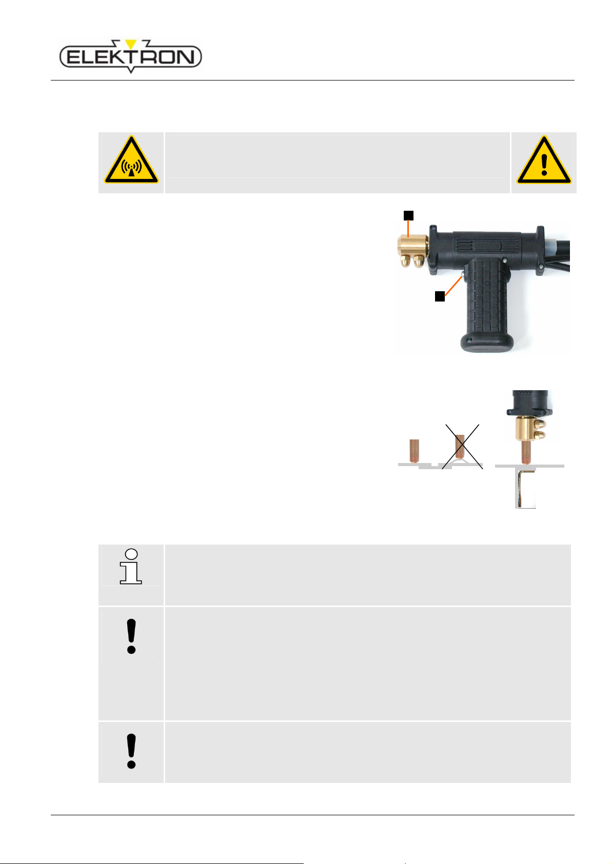
Resistance welder MULTISPOT MI-100control
Caution!
Electromagnetic fields!
CAUTION!
6.9 Operating the welding gun
6.9.1 Push spot welding
Wear protective goggles and gloves!
Electrodes heat up! Flying sparks!
Only use the mode “push spot welding” is the area to be
welded cannot be reached with the spot welding pliers!
1. Grind sheet surface and the area between the sheets until
completely bare.
2. In the welding area the sheets must have direct contact
without air gap. Otherwise welding is impossible.
3. Check the condition of welding electrodes and grind them,
if necessary.
4. Ensure perfect earthing to bottom sheet as close to the
welding spot as possible.
Operation
1
2
Fig. 92: Welding gun
Contact piece (1) / Release button (2)
Select mode “push spot welding” and sheet thickness on
display
(Thickness of more than 1.5 mm cannot be selected!)
Press the welding gun to the welding point with a pressure of
approx. 0.78 – 0.12 daN.
NOTE!
Excessive contact pressure will lead to poor welding results when the distance to the
ground connection is too great.
Inadequate contact pressure – air gap or paint (grease) between the steel sheets –
will result in the upper sheet being burnt through and the electrode cap destroyed.
The air cooling for the spot gun is activated for approx. 15 sec. after the first spot.
When the gun is hot, the cooling run continuously until the gun has cooled down to
approx. 40 °C.
Do not switch the unit off during the cooling phase to prevent any heat congestion.
Keep hold of release button of the gun until welding process has ended
Fig. 93: Pressure on welding point
Always spot-weld thinner sheets to thicker ones!
Proceed with welding towards the grounding point.
Spacing between the welding spots approx. 20 mm.
67
Page 68

Resistance welder MULTISPOT MI-100control
Operation
6.9.2 Pulling-out dents with washer
1. Grind the damaged area to a bright metal finish.
2. Insert contact piece U-B (Fig. 94) into welding gun.
3. Select “washer” mode and sheet thickness on display.
(Sheet steel thickness more than 2 x 1.5 = 3 mm cannot
be selected).
4. Fine-adjust +/–.
5. Position welding gun with washer in the area of the dent.
6. Press release button of the gun.
7. Hook pulling tool (Fig. 95) into the washer and carefully
beat out the dent.
8. Remove washer by twisting. Only twist the washer off,
otherwise holes in the sheet steel could result.
Fig. 94: Contact piece U-B
NOTE!
8 mm Washer. Always beat out major dents from the outside, working inwards.
Use bright washers instead of galvanized.
Adjust setting on display according to size and type of the dent, if necessary.
Fig. 95: Pulling tool
68
Page 69

Resistance welder MULTISPOT MI-100control
CAUTION!
6.9.3 High-speed planishing hammer “SAH” (special accessory)
Small dents, scratches or hail pitting can easily be removed with the high-speed planishing
hammer.
1. Grind damaged area to a bright metal finish.
2. Insert high-speed planishing hammer (with weld on tip)
into the gun (Fig. 96).
3. Select “SAH” mode and sheet thickness on display (Sheet
steel thickness above 0.8 mm cannot be selected).
4. Fine-adjust +/–, if necessary.
5. Position weld-on tip of the hammer in the damaged area.
6. Press release button of the gun and weld-on welding tip.
7. Beat out the dent.
8. Twist the high-speed planishing hammer (SAH) off the
sheet steel. Select the weld time as short as possible.
9. From time to time, dress the weld-on tip with a file.
Operation
Fig. 96: High-speed planishing hammer ‚SAH’
(special accessory)
NOTE!
Repeat the procedure until the damaged area is entirely repaired.
Heavy dents only remove with extractor tool and 8mm washer, as otherwise the
welding gun might be damaged!
NOTE!
If the weld-on tip is worn out, it should be replaced.
For replacement unscrew the socket-head cap screw at the top of the hammer (SAH)
and remove the worn out weld-on tip. Position new weld-on tip and properly tighten
socket-head cap screw!
For item number please see spare parts list.
69
Page 70
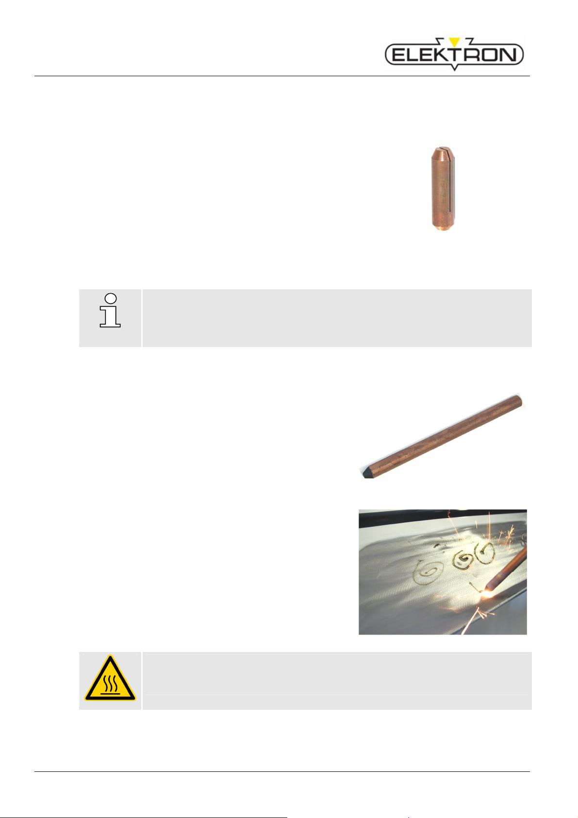
Resistance welder MULTISPOT MI-100control
1.
Danger!
Danger of injury and fire!
Operation
6.9.4 Pushing-in dents
Small high spots dents caused by overlapping load in the boot or by beating out with pulling tool can
easily be flattened with contact piece (only for sheets up to 1 mm thickness).
Insert contact piece U-B (Fig. 97) into the gun.
2. Select “pushing in dent” and sheet thickness
(≈ projection) on display.
3. Fine-adjust, if necessary.
4. Position welding gun with contact piece U-B on the dent
and press firmly.
5. Press release button of the gun.
6. The welding program performs automatically.
NOTE!
Do not lift off welding gun until the welding time has expired
Fig. 97: Contact piece U-B
6.9.5 Shrinking sheet
1. Grind damaged area to a bright metal finish.
2. Insert carbon electrode (Fig. 98) into contact piece of the
welding gun.
3. Select “anneal/shrink” on display (time controller is now
inoperative).
4. Locate the damaged area by finger pressure.
5. Position carbon electrode in the centre of the damaged
area.
6. Press and keep hold of release button of the gun and
heat the metal sheet with spiral motions from the centre
outwards.
7. Immediately quench the sheet with a wet cloth or
compressed air.
Repeat if necessary.
If necessary, the degree of annealing can be increased or
decreased on the display (sheet gauge) by one level up
or down.
Fig. 98: Carbon electrode
70
The carbon electrode becomes red-hot!
Wear protective gloves!
Page 71

Resistance welder MULTISPOT MI-100control
6.9.6 Welding-on threaded studs
With the MULTISPOT MI-100control it is possible to weld on threaded studs of 4, 5, 6 mm diameter.
Please use the appropriate contact pieces (SB 4 for Ø 4 mm / SB 5 for Ø 5 mm / SB 6 for Ø 6 mm)
1. Insert appropriate contact piece (Fig. 99) into welding
gun.
2. Insert threaded stud into contact piece until limit stop.
3. Select “weld on studs” mode and sheet thickness on
display.
4. Decrease power by one step for studs of 4 mm Ø.
5. Increase power by one step for studs of 6 mm Ø.
6. Position welding gun with the stud at the welding point
and press slightly.
7. Press and keep hold of release button of the gun until
welding program has ended.
Operation
Fig. 99: Contact piece SB „threaded stud”
Threaded studs without collar can also be welded on. Use a nut in place of a collar.
The part to be welded should project from the nut about 1 to 2 mm. Welding procedure as described
above.
71
Page 72
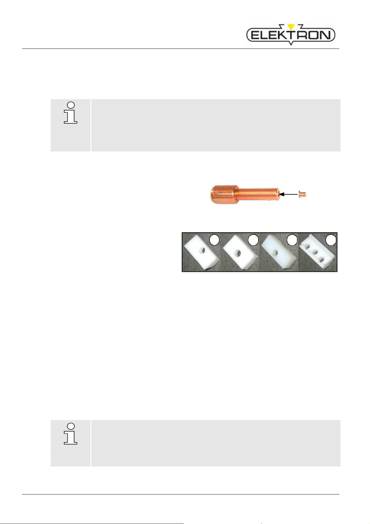
Resistance welder MULTISPOT MI-100control
1
2
3
4
5
6
7
8
5
6
6
Operation
6.9.7 Welding-on T-pins
For example T-pins used for fixing trim strips, can be welded on using contact pieces TST 3 and
TST 5 Incorporated in the tip of the contact piece is a magnet which holds the T-pin during the welding
process.
NOTE!
Special fittings are available for welding works on roof areas of the vehicle types Golf 2,
Golf 3, Vento, Porsche 944 and Passat B3.
These fittings permit accurate welding on of the T-pins exactly at the points specified by
the vehicle manufacturers.
For item numbers please see accessories list!
Welding procedure:
1. Grind welding area to a bright metal
finish.
2. Select appropriate contact piece TST
(Fig. 100) and insert until limit stop into
welding gun.
3 Select “T-pin” mode and sheet thickness
on display.
4. Insert head of T-pin into tip of contact
piece.
5. Select welding position and press-on
welding gun.
6. Press and keep hold of release button of
gun until end of welding program
Fig. 100: Contact piece TST
3
Fig. 101: Fitting piece
4
Contact piece TST 3 Item.-no.: 407 227
T-pin 3 x 4,5 Item.-no.: 408 597
Fitting piece Golf 2 Item.-no.: 313 451 Special accessory!
Fitting piece Passat B 3 Item.-no.: 315 671 Special accessory!
Fitting piece Porsche Item.-no.: 314 465 Special accessory!
Fitting piece Golf 3 / Vento Item.-no.: 317 962 Special accessory!
Contact piece TST 5 Item.-no.: 408 540 Special accessory!
T-pin 5 x 10 Item.-no.: 408 571 Special accessory!
NOTE!
T-pins of Ø 5 x 10 mm can be welded on using contact piece TST 5.
Select “stud welding” and sheet thickness on display.
Fine-adjust, if necessary.
Otherwise, proceed as described above.
72
Page 73

Resistance welder MULTISPOT MI-100control
6.9.8 Fixing sheet metal parts (tacking)
Body sections frequently have to be fixed temporarily for the purpose of alignment. In some areas,
clamps cannot be used.
In such cases, the sections can be fixed by tack welding with the MULTISPOT MI-100control.
Washers from which ¼ has been cut out can be used as fixing aid.
1. Insert contact piece U-B for washers into welding gun to
limit stop.
2. Cut off approx. ¼ of a washer of 8 mm Ø with a side
cutter.
3. Insert prepared washer into contact piece.
4. Select “washer weld” and sheet thickness on display.
5. Position the washer and press-on.
6. Press and keep hold of release button of the gun until end
of automatic welding program.
6.9.9 Water-cooled spot welding gun (special accessory)
Operation
Fig. 102: Contact piece U-B
The water-cooled spot welding gun can only be used for one-sided spot welding (push spots)!
1. Insert spot welding gun in the central socket of the welder unit. (Unit changes over
automatically to the right gun symbol).
2. Connect the cooling water feed pipe and return pipe to the corresponding connections of the
welder unit.
3. Clamp the copper ground lug to the body.
Caution: ensure there is good current conduction!
4. Proceed with spot welding as described in 6.9.1
5. Instead of the ground lug, a second gun can be connected (switch welder unit off first and
wait until cooling pump switches off automatically) so that 2 spot welds can be carried out at
once. This is useful, if the ground lug cannot be fitted. The welding procedure can only be
triggered with one gun.
6. After finishing the welding task, let the cooling pump run on for a while to prevent heat
congestion.
6.9.10 Connection of Airpuller/ Dentpuller
1. Connect Airpuller / Dentpuller to central socket of the welder unit.
2. The unit will switch automatically to the “Special” symbol on the display.
3. Select on control panel “SPECIAL tool” (only by using Airpuller without coding)
4. In “planishing” mode select sheet thickness (up to a max. of 2 x 1 mm) on display.
NOTE!
In select operating mode "annealing" on the control panel "annealing".
Fine-adjust on control panel, if necessary.
Operating the Airpuller please see operating instructions Airpuller
73
Page 74
Resistance welder MULTISPOT MI-100control
WARNING!
People with insufficient skills may suffer injuries!
F01
Nothing, the control unit has
F02
F04
F05
Troubleshooting
7 Troubleshooting
7.1 Health and safety during troubleshooting
If you carry out troubleshooting and repairs yourself, you may encounter certain risks
and hazards that may entail severe injuries.
Therefore:
Do not open the welder. Do not modify the welder. Do not try to carry out repairs
yourself.
For any and all troubleshooting measures not explicitly mentioned and / or
described in this manual, you should call service personnel and / or contact the
manufacturer.
Be sure to adhere strictly to the hierarchy of responsibilities defined in the table.
When you're in doubt: do contact service personnel / manufacturer.
If damage does occur: minimise, contain and avert consequential damage.
NOTE!
In the event that problems occur more frequently due to above-average workloads,
you must adapt the inspection and maintenance intervals accordingly.
7.2 Error messages and troubleshooting tables
7.2.1 Problems displayed on the control panel
Message What’s the problem What should be done?
There has been some problem, and
Welding job has been
successfully re-adjusted
Welding not sufficient. –
Urgently repeat. – Check
contacts and / or mains.
Automatic tool recognition
not possible. Please select
a tool.
At least 1 mains phase is
missing. – Please check
power supply.
the welder has re-adjusted the weld
parameters accordingly.
Sheets may have been insufficiently
prepared.
Power supply too weak.
Problem with pliers and / or caps.
Problem with line-up.
The ID code of the tool installed is
unknown or defective.
A mains phase is missing. Check the supply from the
A mains fuse has been triggered.
An internal fuse has been triggered.
solved the problem.
Hunt down the problem by
elimination and solve it.
Check the tool. Replace, if
necessary. Set the tool
manually.
( “6.4.4”).
mains of the operating
company.
Who should
do it?
---——
Operator
Operator
Skilled
electrician
74
Page 75

Resistance welder MULTISPOT MI-100control
F06
F07
F09
F33
F34
The central connection is overheated.
F35
F36
F37
F38
Message What’s the problem What should be done?
Pliers control not
connected. Please connect
plug.
Work pressure too low.
Timeout occurred on CAN
bus
Please check cap and
change cap, if necessary.
The plug for measuring the
Replace plug. Operator
impedance at the front sheet has not
been connected.
The impedance measuring cable is
defective.
Check the cable.
If the cable must be
replaced, call service.
The IO board is defective. Call service.
Compressed air has not been
connected. Pressure too low.
Check compressed-air
connection and –pressure
“5.6”.
The CAN bus between the control
Check the cables installed. Service
unit and IO board detected too many
errors.
Message appears at start-up and
after 50 welding spots.
Check the caps. Mill them /
replace them, if necessary.
“6.1.2”.
Troubleshooting
Who should
do it?
Operator
Operator
Central connection
overheated.
No tool recognised. Please
insert a tool.
Wrong tool for selected
program – Please connect
tool as per indication.
No electrode identification
available. – Select type of
electrode.
Tool is overheated. –
Welder remains locked until
cooled off.
Interrupt current welding
Operator
job. Let the pump run.
Central connection is not tight. Re-tighten.
The plug of the temperature sensor
Re-tighten.
has gone loose.
A tool has not been connected. Connect a tool. Operator
Otherwise, the tool must be
Replace the tool.
defective.
The tool connected is not right for the
welding program that has been
selected.
(Message can occur only with OEM
Check selected program. Operator
Connect the required tool.
Check the programming.
and own programs.)
You’re using uncoded electrodes. Set the type of electrode
Electrode ID of the tool is defective.
manually
“6.4.3”.
Operator
The impedance measuring cable is
defective.
The tool is overheated. Have the throughput of the
Service
cooling water pump
checked.
Temperature sensor of the tool is
defective.
Have the temperature
sensor of the tool checked.
The throughput of water inside the
tool is too low.
Have the throughput of the
cooling water pump
checked.
75
Page 76

Resistance welder MULTISPOT MI-100control
F39
F41
F42
F43
impossible. You can only enter a date
F44
F46
Days until registration of the
F47
F48
F49
F51
F52
Troubleshooting
Message What’s the problem What should be done?
The power section is overheated. Service personnel only. Service
Power section is
overheated. –
Welder remains locked until
cooled off.
Power section is faulty. –
Call service.
The fan is defective.
The plug of the temperature sensor
has no contact.
The power section is faulty. Service personnel only. Service
Who should
do it?
Invalid date and time. –
Set date and time again.
Wrong date or time. –
Please enter current date
and time.
Software error. –
Please copy software a
second time.
control becomes necessary.
Invalid release key (expired
or copy). Please remove
the card.
The clock of the control unit has not
been set yet.
The buffer battery of the control unit
is empty.
You have entered a date or time that
is already in the past. This is
and time of the future.
The system has detected an error in
the software.
This shows the number of days until
menu item „Program selection” will
be blocked. If the display runs down
to zero days, you can only use the
keyboard programs. However, the
welder can be released at any time.
The key file on the CF memory card
is invalid.
Set the clock
Operator
“6.7.1.8”.
Service personnel only. Service
Set the clock
Operator
“6.7.1.8”.
Carry out an update with
Operator
.elk files ( “6.8”).
“6.3.2” Operator
Order a new key file from
Operator
ELEKTRON.
Control lead / IO interface
faulty. Call service.
CF card missing.
Storage error.
Active fuse protection.
Please wait.
76
No communication between control
unit and IO board.
IO board defective.
CAN bus cable have not been
connected to control and / or
IO-board.
The CF memory card has not been
inserted into the control unit.
Welding spots could not be saved to
CF memory card. Card defective.
Fuse protection has been switched
on and is active.
Service personnel only. Service
Check the status of the CF
Operator
memory card.
( see “6.8”.)
Check CF memory card.
Operator
Replace, if necessary.
( see “6.8”.)
see “6.7.1.6” Operator
Page 77

Resistance welder MULTISPOT MI-100control
F53
F54
for a
F55
F56
F57
F59
F62
F63
F64
F66
Message What’s the problem What should be done?
Reduce current by 5 %?
You are not authorised for
this menu.
You need a CF card with
lower release level.
Entry of user identifier
absolutely necessary.
Entry of order number
absolutely necessary.
Current order data?
The system has detected that a fuse
was triggered. It is now possible to
reduce the weld current by 5 %.
The access rights stored on the
current CF memory card do not allow
you to modify these settings.
During the configuration of the
welder, it was decided that a user
name must be entered.
During the configuration of the
welder, it was decided that an order
number must be entered.
This message appears after one
hour, if order data has been entered
and the order has not been
concluded yet.
Troubleshooting
Who should
do it?
However, you must
determine yourself whether
the results will be
satisfactory or not. If yes,
confirm.
If you absolute require the
rights, call ELEKTRON
new key file.
see “6.7.1”
see “6.7.1.1” Operator
Acknowledge the dialogue.
If necessary, enter data a
second time.
Operator
Operator
Operator
Faulty welding cannot be
recognised by deactivated
safety routines.
Internal flash error.
File header faulty. Delete
data.
Conflict of versions IO
board / system controller
Different setting data in I/O
and system board. Restore
data from I/O System Abort.
One or several safety rules have
been switched off.
If a problem should occur during
welding, the system cannot adjust.
The internal memory is damaged and
/ or does not contain any data.
An error occurred while trying to write
data into memory during an update.
The .elk files of an update are not
compatible with the welder’s current
software. Update will be aborted.
The software of the control unit and
IO board are not compatible with
each other. This can occur, for
instance, after electronic components
have been replaced.
Comparison of IO board data and
control unit data not successful. The
control unit has a backup file of this
very important data package. So, the
message will always occur after one
of the two components has been
replaced.
You must determine
Operator
yourself whether the results
will be satisfactory or not. If
yes, confirm.
Service personnel only. Service
Contact ELEKTRON and
Operator
ask for new .elk files. Be
sure to state correct
software version.
Service personnel only. Service
Press button “IO” or
Service
“System” to select which
component should be used
to restore the data. Be sure
to select the component
that has NOT been
replaced.
77
Page 78

Resistance welder MULTISPOT MI-100control
Troubleshooting
7.2.2 Problems NOT displayed on the control panel
Message What’s the problem What should be done?
Welder does not boot up. Emergency stop pushbutton has
been pushed and is now locked.
Power cord not plugged in. Plug in power cord.
If the power cord is, indeed,
connected, a mains fuse may have
been triggered.
Display freezes.
System error. Reboot. Operator
LEDs not plausible.
The red LED to the left of
Thermal overload. Let the welder cool off. Let
the control knob lights up.
Tool error. Let the tool cool off. If
Mains disturbance. Check fuses and input
Who should
do it?
Unlock pushbutton. Operator
Reset fuse.
Operator
the cooling system run at
least 10 mins. After you
finish.
necessary, replace.
values ( “6.7.2.8”).
78
Page 79

Resistance welder MULTISPOT MI-100control
If that doesn’t do it, fall back
If that doesn’t do it, fall back
Troubleshooting
7.2.3 Possible causes and remedies in case of unsatisfactory welding results
Symptom Possible cause Remedy
Weld spot too small Weld current too weak. Adapt welding parameters.
Weld time too short.
on pre-defined programs
and / or keyboard mode.
Wrong welding program. Select correct welding
program.
If in doubt, talk to the
manufacturer and / or OEM.
Welding spot burns up,
excessive spattering,
sheets not strong enough.
Weld current too high. Adapt welding parameters.
Weld time too long.
on pre-defined programs
and / or keyboard mode.
Wrong welding program. Select correct welding
program. If in doubt, talk to
the manufacturer and / or
OEM.
WHO should
do it?
Operator
Operator
Operator
Operator
Welding job flawed Welding parameters not set correctly
according to requirements.
Sheets may have been insufficiently
prepared.
Setting / operating error(s) within the
operating mode set.
Use the “Info” button to call
Operator
up the values set. Compare
to your specs.
“6.1.1” Operator
“6.4.2” If in doubt,
Operator
contact manufacturer.
79
Page 80

Resistance welder MULTISPOT MI-100control
Maintenance
8 Maintenance
8.1 Maintenance schedule
Intervals What must be done?
Visually check the welder and its periphery for damage, dirt, contamination
etc.
Clean, if necessary ( see “8”).
Check connections for tight fit.
( see “5.5” – “5.7”).
Check compressed-air supply.
Before ANY
maintenance job
Every 6 months
( see “5.6”
Check level gauge. Cooling water level okay?
Fill up, if necessary. ( see “5.2”).
Visually check electrode caps. If necessary, clean, mill and / or replace.
( see “6.1.2”).
Check distance and –alignment of electrodes. ( see “6.1.2”).
Check PPE for functionality. Replace, if and as soon as necessary.
Check purity and quality of operating company’s compressed-air supply.
Check the work environment. Does it still fulfil all the operating requirements?
( see “9.4”).
Check actual input current and voltage. Take your own measurements. Skilled
Who should
do it?
Operator
Operator
electrician
Use the CF memory card to make data backups. Store externally.
Visually check the water separator and air filter of the pneumatic unit. Carry
Whenever
necessary
out jobs as required. ( see “8.2.2”).
Visually check the water filter. Replace, if necessary.
( see “8.2.3”).
Empty cooling water tank ( see “8.2.3”). Refill ( see “8.2.4”).
8.2 Carrying out maintenance jobs
Personnel
The maintenance jobs described here may be carried out by operators, if not explicitly stated
otherwise.
Have works on electrical equipment carried out by skilled electricians, exclusively.
Operator
80
Page 81
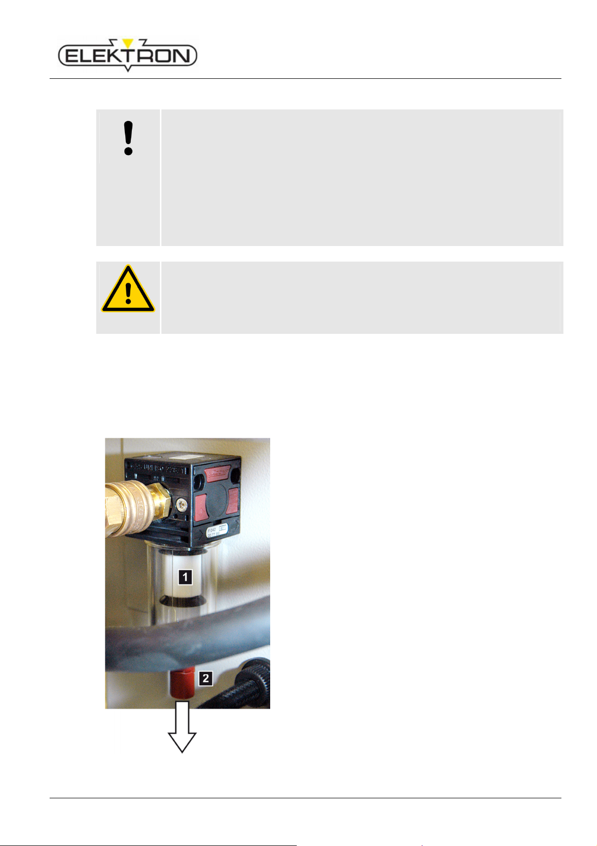
Resistance welder MULTISPOT MI-100control
CAUTION!
Failure to carry out
and / or
negligent or improper cleaning jobs
WARNING!
Wrong spare and
wear parts constitute a hazard!
8.2.1 Cleaning
may entail damage to property!
If you do not clean the welder at all or use aggressive cleaning agents or –methods,
there is a danger of damage to property.
Therefore:
Do not use aggressive cleaning agents and / or –methods.
Do not use steam cleaners and / or pressure washers.
Be particularly careful with the display.
Be sure to clean the welder on a regular schedule, especially around air vents.
Adequate dissipation of heat must be ensured.
Wrong and / or defective spare and wear parts may constitute a safety hazard and may
entail errors, damage and even total destruction.
Therefore:
Always use genuine spare and wear parts made by the manufacturer.
Clean the welder with a dry, lint-free cloth. For persistent dirt, use a textile cloth that has
been slightly damped with a mild detergent.
As for the display: just dust. Be careful not to scratch the display.
8.2.2 Maintaining the pneumatic unit
Maintenance
Fig. 103: Pneumatic unit
1. Visually check the compressed-air filter (Fig. 103/1).
Replace, when you see any accumulation of dirt.
2. Visually check the water separator (Fig. 103/2)
under the compressed-air filter for residues of water.
If you find any accumulations of water, pull of the cap in
the direction indicated by the arrow and empty water from
the separator.
81
Page 82

Resistance welder MULTISPOT MI-100control
DANGER!
Scalding may occur due to hot water coming out!
DANGER!
Slip hazard due to water coming out!
Maintenance
8.2.3 Replacing water filter
Scald hazard
While pulling out the cooling water hoses hot water may come out.
Therefore:
Wear gloves.
Pull out water hoses carefully.
Slip hazard
While pulling out the cooling water hoses water may come out.
Therefore:
Remove water from the floor.
Fig. 104: Water filter
1. Visually check the water filter (Fig. 104).
If you detect clear signs of dirt:
2. Switch off the welder. Wait, until the pump stops pumping.
3. Pull the water filter unit from the hoses to the top and
bottom.
4. Replace the old filter with a new one.
5. Insert the new water filter between the hoses.
82
Page 83
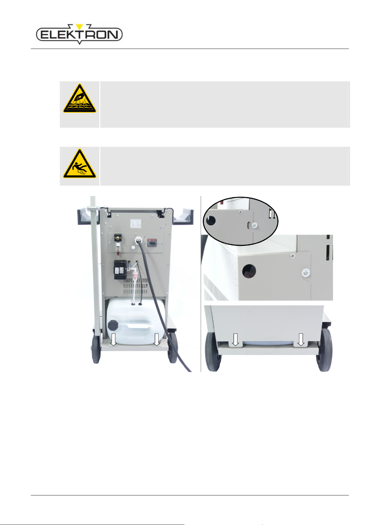
Resistance welder MULTISPOT MI-100control
DANGER!
Scalding may occur due to hot water coming out!
DANGER!
Slip hazard due to water coming out!
1.
8.2.4 Empty cooling water tank
Scald hazard
While pulling out the cooling water hoses hot water may come out.
Therefore:
Wear gloves.
Pull out water hoses carefully.
Slip hazard
While pulling out the cooling water hoses water may come out.
Therefore:
Remove water from the floor.
Maintenance
Fig. 105: Filling up the cooling water tank
Remove rear cover, pull out forward and return hose from the cooling water tank.
2. Cooling water tank carefully pull out, straighten up and turn off cooling water tank cap.
3. Cooling water tank emptying, observing disposal regulations.
4. Fill about 30 litres / 7.9 gallons of cold, clean drinking water into the tank.
5. Add chlorine-free disinfectant to prevent growth of algae and bacteria.
6. Cooling water tank cap firmly turn up again. Check tightness.
7. Cooling water tank reinstall. Put forward and return hose into the coolant tank and plug back cover
down and hang up.
8. Before you switch on the welder, check the coolant level before each use and, if necessary, top up
coolant.
83
Page 84

Resistance welder MULTISPOT MI-100control
Maintenance
8.3 Measures to be taken after maintenance
When you finish maintenance and before you switch the welder back on, carry out the following:
1. Re-establish any and all connections you loosened and / or removed before.
Check for tight fit.
2. Make sure any and all safety devices, covers etc. you may have removed are properly back
in place.
3. Make sure you have properly removed and taken away from the work area any and all tools,
materials etc. you may have used.
4. Clean the work area. If there have been any leaks, spills etc., clean up.
84
Page 85

Resistance welder MULTISPOT MI-100control
32 63
42 42
60 60
23 23
9 Specifications
9.1 Dimensions and weights
Item Value Unit
Height 1100 /43 mm / in
Width 690 /27 mm / in
Depth 600 /23.6 mm / in
Weight (w/o accessories) 100 / 220 kg / lb
9.2 Power requirements
Power supply
Item Value Value Value Unit
Mains voltage 480 / 3 ~
Admissible voltage range 440 – 500 380 – 415 208 – 240 V (AC)
50 / 60
400 / 3 ~
50 / 60
230 / 3 ~
50 / 60
Specifications
V / Ph
Hz
Power cord 6
AWG 10
Mains fuse, min. 32
Installed power 42
Rated output at 50% duty cycle 60
No load voltage, max. 23
weld current, regulated, max. 12000
Enclosure IP21
Compressed-air supply
Item Value Unit
Operating pressure, min. – max. 6 – 10
87 – 145
Quality clean, dry, free of oil
Cooling water pump
Item Value Unit
Operaiting air pressure 6 / 87 bar / Psi
AWG 10
bar
Psi
6
12000
16
mm2 / 10 m
AWG 6
12000 A (DC)
33 ft
A slow-blow
kVA
kVA
V (DC)
Flow rate 2.5 /0.66 l/min / gal
85
Page 86

Resistance welder MULTISPOT MI-100control
1
Specifications
9.3 Supplies
Item Value Unit
Cooling water – tank capacity ca. 30
Chlorine-free disinfectant accor. dosing instructions
9.4 Working conditions
Ambient conditions
Item Value Unit
Ambient temperature, max. 40 / 104 °C / °F
Rel Humidity, max.
(no dew)
9.5 Exposure limit values
Welding pliers
Item Compliance
Exposure limit values accor.
EU directive 2004/40/EG
9.6 Type plates
7.9
85 %
l
gal
Safe compliance with distances
≥ 15 cm perpendicular to pliers opening.
Safe compliance with distances
≥ 7 cm to welding cable.
Fig. 106: Type plate on the backside
Manufacturer
2 Inverter type
3 Item no.
4 Input voltage (in VAC)
5 Frequency (in Hz)
6 Power consumption (in kVA)
7 Enclosure
8 Production no.
9 Duty cycle (in %)
10 Max. current (in A)
11 Output voltage (in VDC)
12 Appeal:
Read operating manual. Comply with operating manual!
86
Page 87

Resistance welder MULTISPOT MI-100control
10 Index
A
Accessories .......................................................... 30
Adjusting the distance between electrodes .......... 40
Airpuller ................................................................. 73
Ambient conditions ............................................... 86
Appendix ............................................................... 89
Assembling the balancer ...................................... 33
B
Basic settings ........................................................ 43
Batteries ................................................................ 21
C
Calling up status and error messages .................. 63
Calling up the software version ............................ 64
Changing configuration ......................................... 61
Chlorine-free disinfectant ...................................... 85
Cleaning ................................................................ 81
Compressed-air supply ......................................... 85
Concluding an order ............................................. 58
Configuration
Loading most recent configuration .................... 61
Connecting welding gun ....................................... 37
Connections .......................................................... 28
Electrical ............................................................ 34
Pliers ................................................................. 36
Pneumatics ....................................................... 35
Contact force ........................................................ 56
Contact person ....................................................... 9
Control elements ................................................... 27
Control modes ...................................................... 45
Control panel ........................................................ 27
Copyright ................................................................ 6
Customer service .................................................... 9
Index
Emergency stop button ......................................... 18
Empty cooling water tank ...................................... 83
Environmental protection....................................... 21
Error messages ..................................................... 74
Exposure limit values ............................................ 86
F
Filling up cooling water tank .................................. 31
Flying sparks ......................................................... 15
Further transport needs ......................................... 25
G
Guarantee ............................................................... 9
H
Handling ................................................................ 23
High-speed planishing hammer ............................ 69
Hot surfaces .......................................................... 15
I
Info button ............................................................. 57
Intended purpose .................................................. 10
Intended use .......................................................... 10
Inverter control unit ................................................ 28
L
Liability..................................................................... 6
M
Maintaining the pneumatic unit ............................. 81
Maintenance jobs .................................................. 80
Maintenance schedule .......................................... 80
Messages displayed on the control panel ............. 74
Misuse ................................................................... 10
D
Dentpuller ............................................................. 73
Description ............................................................ 19
Dimensions ........................................................... 85
Disinfection ..................................................... 31, 83
Display and control elements ............................... 27
E
Electricity .............................................................. 14
Electrode recognition ............................................ 51
Electromagnetic fields ..................................... 14, 53
O
Overview................................................................ 26
P
Personnel .............................................................. 12
Maintenance ...................................................... 80
Power requirements .............................................. 85
Power supply ......................................................... 85
Power switch ......................................................... 18
87
Page 88

Resistance welder MULTISPOT MI-100control
Index
PPE ................................................................. 13, 55
Preparing the sheets ............................................. 38
Preparing welding pliers ....................................... 38
Problems
not displayed on the control panel .................... 78
Welding flaws .................................................... 79
Push spot welding ................................................. 67
Pushing-in dents ................................................... 70
R
Registering ............................................................ 44
Replacing water filter ............................................ 82
Responsibilities of the operating company ........... 10
Return of goods .................................................... 25
S
Safety devices....................................................... 18
Safety labels and markings ................................... 19
Safety protection ................................................... 59
Scald hazard ......................................................... 15
Service .................................................................... 9
Service menu ........................................................ 57
Administering programs .................................... 59
Order data ......................................................... 58
Settings (page 1) ............................................... 58
Settings (page 2) ............................................... 60
Settings
Contact force ..................................................... 56
Electrode recognition ........................................ 51
Language .......................................................... 43
Time and date ................................................... 60
Tool selection .................................................... 52
Shrinking sheet ..................................................... 70
Slip hazard ............................................................ 15
Spare and wear parts ........................................... 20
Specifications ........................................................ 85
Splashes ............................................................... 15
Spring balancer .................................................... 33
Storage ................................................................. 25
Stumbling hazards ................................................ 16
Supplies ................................................................ 85
Switching off the cooling water pump ................... 53
Switching off weld rules ........................................ 63
Switching on ......................................................... 42
Symbols
on equipment .................................................... 19
on packaging ..................................................... 22
to be installed by operating company ............... 11
used in the operating manual ............................. 7
T
Tacking ................................................................. 73
Threaded studs ..................................................... 71
Tool selection ....................................................... 52
T-pins .................................................................... 72
Training Report ..................................................... 89
Transport .............................................................. 22
Troubleshooting .................................................... 74
Type plates ........................................................... 86
U
Updating software................................................. 65
V
Vapours ................................................................ 16
W
Washer ................................................................. 68
Waste management ............................................. 21
Weights ................................................................. 85
Welding gun .......................................................... 67
Welding parameters ............................................. 57
Working conditions ............................................... 86
88
Page 89

Resistance welder MULTISPOT MI-100control
11 Appendix
11.1 Training Report
NOTE!
Master copy. Do not fill in. Make copies.
Date Name Type of training Trainer Signature
Appendix
89
Page 90

B l i t z R o t a r y G m b H
Phone +49 / (0)421 / 54 90 6-906 Fax +49 / (0)421 / 54 90 6-19 vertrieb@elektron-bremen.de www.elektron-bremen.de
B r a n c h B r e m e n H i n t e r m S i e l h o f 2 2
D - 28 2 7 7 B r em e n
 Loading...