

Page 1
Operating instructions
MULTISPOT M20
ELEKTRON Bremen GmbH Hinterm Sielhof 22 D-28277 Bremen
Fon +49/(0)421/54906-906 Fax +49/(0)421/5490619 vertrieb@elektron-bremen.de www.elektron-bremen.de
- 1 -
Page 2

Contents page
1.0 Warning notes – explanation of symbols 3
2.0 Description of equipment and overview 5
3.0 Start-up 6
3.1 Connection to power supply 6
3.2 Mains power supply connection 6
4.0 Applications 7
5.0 Technical data 7
6.0 Operating the welding gun 9
6.1 Pulling-out dents with washer 11
6.2 High-speed planishing hammer "SAH" (special accessory) 13
6.3 Pushing-in dents 15
6.4 Shrinking sheet metal 15
6.5 Welding-on threaded studs 17
6.6 Welding-on T-pins 19
6.7 Positioning/fixing sheet metal (tacking) 21
7.0 Appendix/self-test and troubleshooting 22
7.1 Self-test 22
7.2 Checking the LED displays 22
7.3 Mains-supply test and troubleshooting 23
7.4 Manual tool selection 24
7.5 Operating panel malfunction 24
- 2 -
Page 3
1.0 Warning notes – explanation of symbols
Caution!
The power supply unit and leads of the welding gun
and other tools generate a powerful electromagnetic
field when in use. This can cause malfunctions in heart
pacemakers, quartz watches and other electronic devices. Electromagnetic storage devices, e.g. on credit
cards, may be erased.
Caution! Danger!
Ignoring this warning may result in injury!
Observe the notes!
This is the only way to achieve satisfactory welding re-
sults.
Work on the power supply unit may ONLY be performed by qualified electricians.
Wear protective goggles and gloves!
- 3 -
Page 4
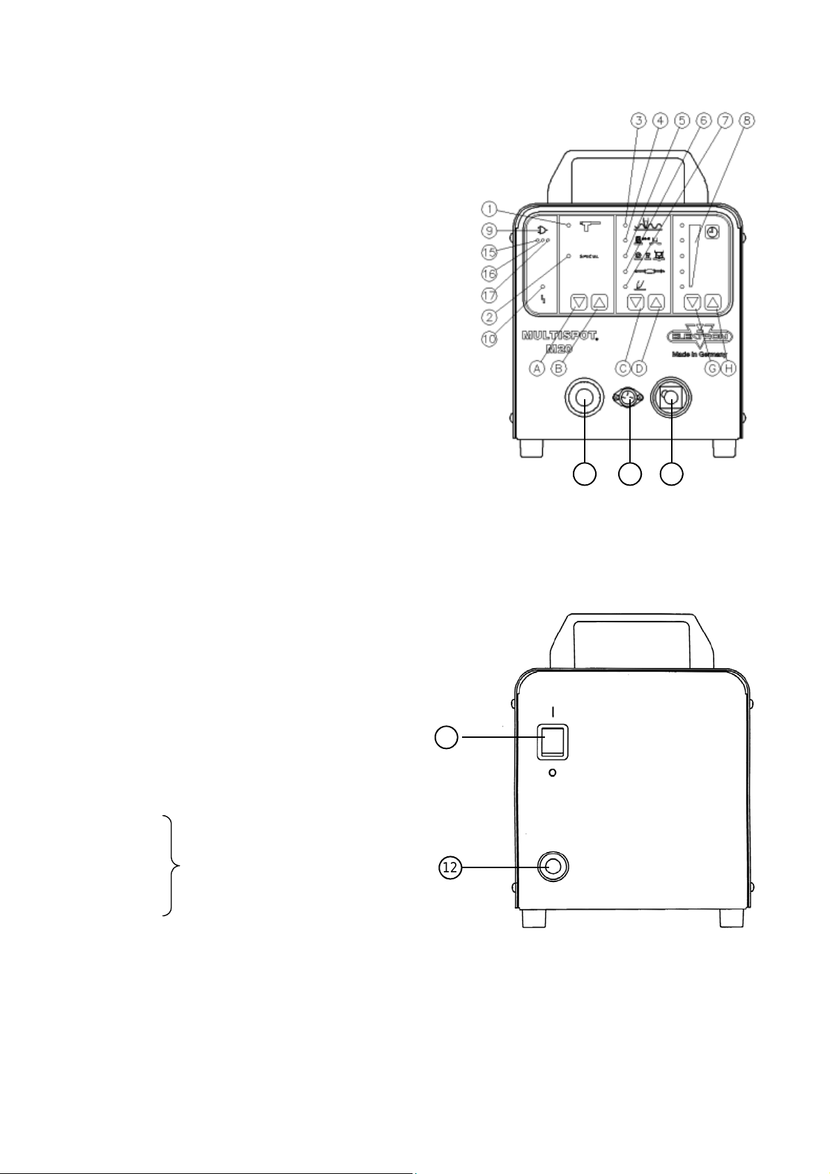
Tool selecting keys (manual) see Appendix
CD Gun functions selecting keys
GH Fine adjustment keys time +/–
Tools
1 Gun
2 Special (e.g. AIRPULLER)
Working with gun
3 Welding of corrugated wire
4 Stud welding/Copper shrinking
5 Beat-out with washers, T-pins,
Special
6 High-speed planishing hammer
7 Anneal/shrink
8 Fine adjustment +/–
9 Mains plug symbols with
LED "control mains voltage drop"
(15, 16, 17)
10 LED malfunction
11 Mains plug
12 Mains cable
15
16 Indicator
18 19 20
M20 – front
11
12
17 “control mains voltage drop“
18 Ground cable
19 Flange socket
20 Welding socket
- 4 -
M20 – back
Page 5

2.0 Description of equipment and overview
The MULTISPOT M20 resistance welding unit is designed for the
special requirements of motor vehicle body repair.
The power source is controlled by a micro-processor. After selecting the operating mode, the current and weld time will be assigned automatically.
An audible alarm is performed, if the welding current is too low.
Further functions:
– Automatic tool recognition
– Integrated mains monitor recognises undervoltage
– Automatic current rise, welding and current recognition
– Easy and distinct operation by means of foil keyboard
- 5 -
Page 6

3.0 Start-up
3.1 Compressed air connection 8 bar
The compressed air connection (8 bar) is located on the back of
the power supply unit. The compressed air supply is necessary for
operating special tools (e.g. Airpuller) and cooling the welding gun.
3.2 Connection to power supply
230 V (205 - 250 V) 50/60 Hz or 400V 50/60Hz
Connection to a 16 A socket 16A-CEE-socket
Fuse: 16 A slow fuse
or
16 A automatic circuit-breaker
3.3 Checking the mains voltage drop during welding
If the full performance of the MULTISPOT M20 is to be obtained,
the mains voltage drop during welding must be kept as small as
possible. The full test is described on page 20 Chapter 8.3:
Information about the mains drop during welding
Display with 3 LEDs (15, 16, 17) under the mains plug
symbol:
Green = mains OK
Green/yellow = mains drop within tolerance range.
Only yellow = considerable mains drop – welding
performance impaired
If necessary, check mains cord, extension cables etc. or use
thicker cables.
Red LED and = large mains drop with high loss in performance
warning tone: Welding is not possible. Welding current too
low.
If necessary, check mains cord, extension cables etc. or use
thicker cables.
– After 2 seconds, the display automatically reverts to green.
– After each welding operation, any mains voltage drop is
displayed for 2 seconds.
- 6 -
Page 7

4.0 Applications
Programme switch Material Max. sheet
Function thickness
in mm
Dent-pulling
with washer sheet steel 1.0
T-pins 3 mm Ø sheet steel 1.0
Dent-pulling with other tools sheet steel 1.0
(e.g. Airpuller)
Dent-pulling with
high-speed
planishing hammer sheet steel 1.0
Shrinking sheet steel 0.6 - 1.0
Stud welding Steel bolts Ø 4 - 5 mm
on sheet steel 2.0 mm
Corrugated wire on sheet steel 1.0
Copper shrinking sheet steel 1.0
5.0 Technical data
Power supply unit 230 V (205 - 250 V) 400V
Supply voltage 1x230 V (1~) 400V (2~)
Slow fuse 16 A 16A
Mains frequency 50/60 Hz 50/60 Hz
Power supply cord 3.3 kVA 3.3 kVA
Max. welding capacity 11 kVA 11 kVA
Open-circuit voltage 8 V AC 8 V AC
Welding current max. 3000 A 3000 A
Ambient temperature 40 °C 40 °C
Type of protection IP21 IP21
Power supply unit with Dinse-plug
Dimensions H/W/D in mm 285/220/340
Weight 21 kg
(standard version)
- 7 -
Page 8
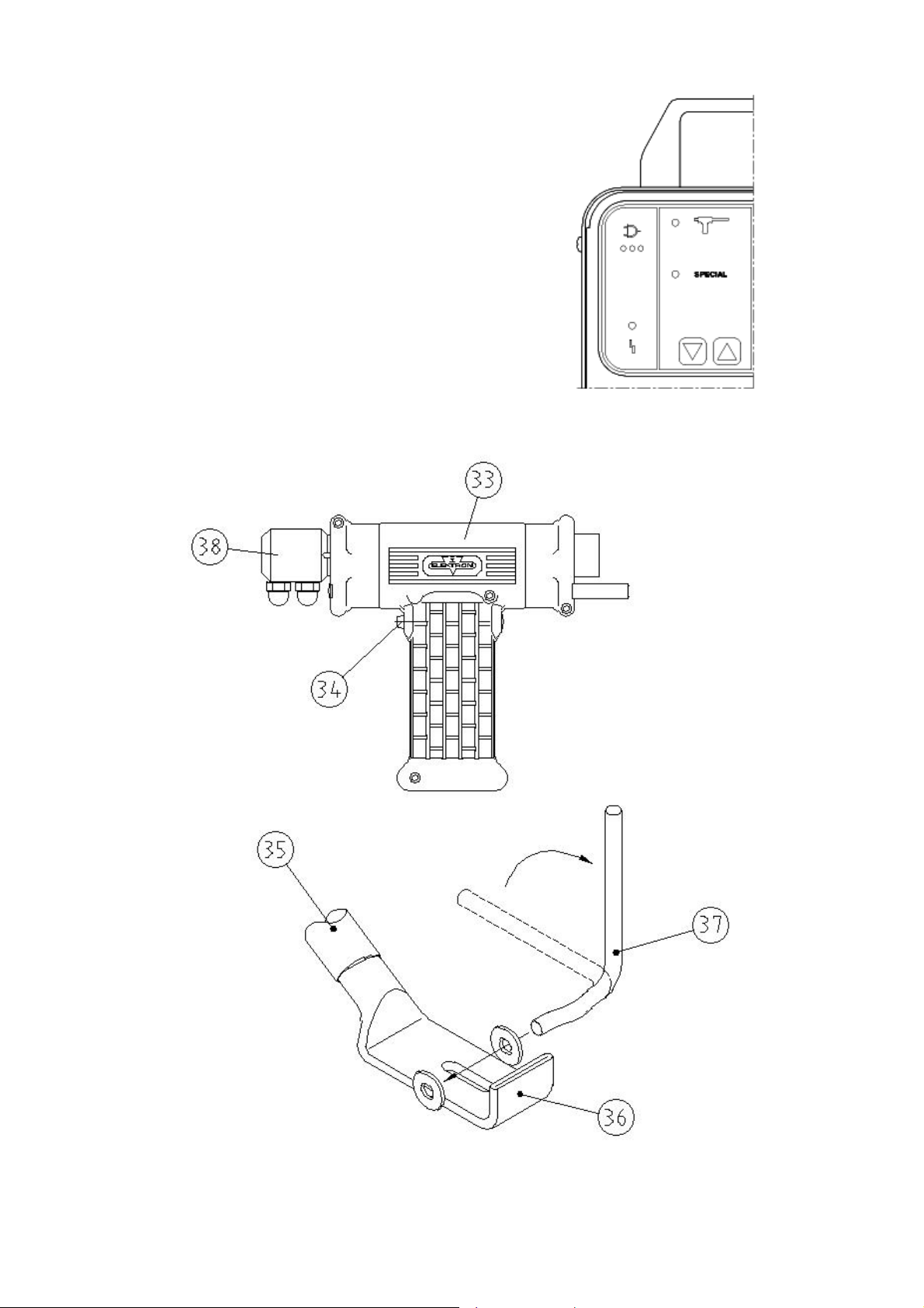
33 Welding gun
34 Button of welding gun
35 Grounding cable
36 Copper shoe
37 Lever clamp
38 Connection piece
A B
- 8 -
Page 9

6.0 Operating the welding gun
Preparation:
Insert the central plug of the welding gun (33) into the central
socket (63) until limit stop. Arrow on the plug pointing upwards.
The unit will switch automatically to the "gun" symbol.
Select the "gun" tool with key AB (uncoded gun only).
Connect the copper shoe (36) of the grounding cable (35) to
a bare point on the bodywork to be welded. Use lever clamp
(37) provided or a mole wrench.
Before using the lever clamp (37), you have to weld on two
8 mm washers as close to the point of weld as possible, see
section 6.1! In this case, press the copper shoe (36) of the
grounding cable (35) firmly onto the metal sheet. This is the
only way to obtain a good current transfer.
Attention!
The copper shoe (36) must always be connected to the metal
sheet below the metal part of the body to be worked on.
In any case avoid current transfer via hinges, door and bonnet locks, as these might otherwise be damaged!!
- 9 -
Page 10

A B C D G H
40 Contact piece UB
41 Pulling tool
- 10 -
Page 11

6.1 Pulling-out dents with washer
Grind the damaged area to a bright metal finish.
Insert contact piece (40) into welding gun.
Select "washer" mode with keys CD.
Fine-adjust +/– with keys GH, if necessary.
Position welding gun (33) with washer in the area of the
dent.
Press button (34) of the gun.
Hook pulling tool into the washer (41) and carefully beat out
the dent.
Remove washer by twisting. Only twist the washer off, other-
wise holes in the sheet steel could result.
8 mm Washer
Always beat out major dents from the outside, working in-
wards.
Use bright washers instead of galvanized. Adjust setting
with keys GH according to size and type of the dent, if necessary.
- 11 -
Page 12

A B C D G H
42 High-speed planishing hammer "SAH", special accessory!
- 12 -
Page 13

6.2 High-speed planishing hammer "SAH"
(special accessory)
Small dents, scratches or hail pitting can easily be removed with
the high-speed planishing hammer (42).
Grind damaged area to a bright metal finish.
Insert high-speed planishing hammer (42) (with weld on tip)
into the gun.
Properly tighten union nut.
Select "SAH" mode with keys CD.
Fine-adjust welding time with keys GH, if necessary. Select
the weld time as short as possible.
Position weld-on tip of the hammer (42) in the damaged area.
Press button (34) of the gun and weld-on welding tip.
Beat out the dent.
Twist the high-speed planishing hammer (SAH) off the sheet
steel.
From time to time, dress the weld-on tip with a file.
Repeat the procedure until the damaged area is entirely re-
paired.
Heavy dents only remove with extractor tool and 8mm was-
her, as otherwise the welding gun might be damaged!
If the weld-on tip is worn out, it should be replaced.
For replacement unscrew the socket-head cap screw at the
top of the hammer (SAH) and remove the worn out weld-on
tip. Position new weld-on tip and properly tighten sockethead capscrew!
For item number please see spare parts list.
- 13 -
Page 14

A B C D G H
A B C D G H
39 Carbon electrode
40 Contact piece U-B
- 14 -
Page 15

6.3 Pushing-in dents
Small high spots dents caused by overlapping load in the boot or
by beating out with pulling tool can easily be flattened with contact piece (40) (only for sheets up to 1 mm thickness).
Insert contact piece (40) into the gun (33).
Thoroughly tighten union nut.
Select "pushing-in dents" mode with keys CD.
Fine-adjust with keys GH, if necessary.
Position welding gun (33) with contact piece (40) on the dent
and press firmly.
Press button (34) of the gun.
The welding program performs automatically.
Do not lift off welding gun until the welding time has
expired!
6.4 Shrinking sheet
Grind damaged area to a bright metal finish.
Insert carbon electrode (39) into contact piece of the welding
gun (33).
Select "anneal/shrink" with keys CD.
Locate the damaged area by finger pressure.
Position carbon electrode (39) in the centre of the damaged
area.
Press and keep hold of button (34) of the gun and heat the
metal sheet with spiral motions from the centre outwards.
Immediately quench the sheet with a wet cloth or compres-
sed air.
Repeat if necessary.
If necessary, the time of annealing can be changed with the keys
GH.
Danger!
The carbon electrode becomes red-hot!
Danger of injury and fire!
Wear protective gloves!
- 15 -
Page 16

A B C D G H
44 Contact piece "threaded stud"
- 16 -
Page 17

6.5 Welding-on threaded studs
With the MULTISPOT M20 it is possible to weld on threaded
studs of 4, 5, 6 mm diameter.
Please use the appropriate contact pieces!
SB 4 for Ø 4 mm
SB 5 for Ø 5 mm
Insert appropriate contact piece (44) into welding gun (33).
Properly tighten union nut.
Insert threaded stud into contact piece (44) until limit stop.
Select "weld on studs" mode with keys CD.
Position welding gun (33) with the stud at the welding point
and press slightly.
Press and keep hold of button (34) of the gun until welding
program has ended. – (Time adjust with keys GH)
Threaded studs without collar can also be welded on. Use a nut
in place of a collar. The part to be welded should project from the
nut about 1 to 2 mm. Welding procedure as described above.
- 17 -
Page 18

A B C D G H
45 Contact piece TST 3 Item no. 407 227 special accessory
47 T-pin 3 x 4.5 . Item no. 408 597
48 Fitting piece Golf 2 Item no. 313 451 special accessory
49 Fitting piece Passat B 3 Item no. 315 671 special accessory
50 Fitting piece Porsche Item no. 314 465 special accessory
51 Fitting piece Golf 3/Vento Item no. 317 962 special accessory
- 18 -
Page 19

6.6 Welding-on T-pins
For example T-pins used for fixing trim strips, can be welded on
using contact pieces TST 3 (45) and TST 5 (52).
Incorporated in the tip of the contact piece is a magnet which
holds the T-pin during the welding process.
Special fittings are available for welding works on roof areas
of the vehicle types Golf 2, Golf 3, Vento, Porsche 944 and
Passat B3. These fittings permit accurate welding on of the
T-pins exactly at the points specified by the vehicle manufacturers.
For item numbers please see accessories list!
Welding procedure:
Grind welding area to a bright metal finish.
Select appropriate contact piece and insert until limit stop into
welding gun (33).
Thoroughly tighten union nut.
Select "T-pin" mode with keys CD.
Insert head of T-pin into tip of contact piece.
Select welding position and press-on welding gun (33).
Press and keep hold of button (34) of gun until end of wel-
ding program. (Time adjust with keys GH)
- 19 -
Page 20

A B C D G H
- 20 -
Page 21

6.7 Fixing sheet metal parts (tacking)
Body sections frequently have to be fixed temporarily for the purpose of alignment. In some areas, clamps cannot be used. In
such cases, the sections can be fixed by tack welding with the
MULTISPOT M20. Washers from which ¼ has been cut out can
be used as fixing aid.
Insert contact piece (40) for washers into welding gun (33) to
limit stop.
Properly tighten union nut.
Cut off approx. ¼ of a washer of 8 mm Ø with a side cutter.
Insert prepared washer into contact piece (40).
Select "washer weld" with keys CD.
Position the washer and press-on.
Press and keep hold of button (34) of the gun until end of au-
tomatic welding program.
- 21 -
Page 22

7.0 Appendix/self-test and troubleshooting
7.1 Self-test
The MULTISPOT M20 is provided with a self-test program to
check and evaluate the functions of the unit.
7.2 Checking the LED displays
Detach the gun from the power supply unit.
Connect the unit to the power supply.
Switch the unit OFF.
Depress key "A", switch the unit ON, release the key "A". All
the LEDs on the operating panel will be switched on in sequence.
The test ends after 5 cycles or when any key is pressed.
7.3 Mains-supply test and troubleshooting
Test procedure:
Connect gun and select the "stud welding" mode:
Time to max: GH keys
Insert spot electrode in the gun.
Press the spot electrode firmly onto the earth shoe (36),
press the gun trigger and perform the short-circuit weld.
Evaluating the test
LEDs under the mains plug symbol:
Green No mains drop, full welding performance
available
Green+yellow Insignificant mains drop, good welding
performance
Yellow Larger mains drop, lower welding performance
Yellow+red Critical mains drop, welding performance not
sufficient
Red Mains drop too great, spot welding is not
possible.
Causes of power drop under load:
Extension cables too long.
Mains power cord from power point (fuse box) to plug is too
long or cable cross-section is too small.
The mains voltage is below the normal value.
- 22 -
Page 23

Self-test and evaluation
For this purpose push button H in panel C longer than
2 seconds.
LEDs in Panel A
Indication code
A 1) System fault EEPROM parameter
– Call service.
A 2) EEPROM operating
– Call service.
LEDs in Panel B
B 1) Power inlet 230 V
B 2) Power inlet 400 V.
B 3) Display of supply frequency 50 Hz
B 4) Display of supply frequency 60 Hz
– Mains voltage is too high.
B 5) Fault frequency – Call service.
LEDs in Panel C
C 1) Tool disconnected / plugged off.
C 2) Tool too hot.
C 3) Tool cooling.
C 4) Transformer too hot.
C 5) Tool with long cable
LED
1
2
3
4
A B C D G H
Panel A Panel B Panel C
- 23 -
5
Page 24

7.4 Manual tool selection
In an emergency or for service examination, it is possible to bypass automatic tool recognition.
Switch the unit OFF.
Connect the tool to the unit.
Switch the unit ON, depressing the tool key.
Select the tool required with the keys AB.
Reset on tool change or switch the unit off.
7.5 Operation panel malfunction
In the case of a malfunction in the operating panel, that is to say
there is no reaction when a button is pressed, if LED displays illuminate incorrectly, etc., switch the unit OFF and switch ON
again after approx. 2 sec. This will clear the malfunction.
Subject to technical alterations without notice.
Item No. 324 631 (GB) Englisch 04/10
- 24 -
 Loading...