

Page 1

ELEKTRON-BREMEN Fabrik für Elektrotechnik GmbH x Postfach 10 59 60 x D - 28059 Bremen
Telefon +49 / (0)421 / 54 90 6-0 x Telefax +49 / (0)421 / 54 90 619 x vertrieb@elektron-bremen.de x www.elektron-bremen.de
Operation Manual
MULTIMIG 400puls
Page 2
2
5
5
6
10
8
9
6
7
12
15
14
11
10
Page 3
3
Use and maintenance of welding and cutting
machines can be dangerous. Please draw
user´s attention to follow the safety precau
tions to avoid injuries. Welding and cutting
machines must be used appropriate and
only by specialist staff. Please inform yourself constantly about the valid safety precautions and regulations of accident prevention by working with this machine*.
Remove all flammable material from the welding area for fire prevention before welding.
Do not weld at containers which were filled up
before with flammable materials (fuel).
All inflammable material in the welding area
which could be inflamed by sparks must be re
moved.
Check after welding the place conforming UVV.
Do not expose the unit to rain, steam and do not
spray water in it.
Do not weld without protection shield. Keep attention to protect other persons in the welding
area against arc-rays.
Please use absorbers or other systems to absorb the gases.
It is not possible to absorb all the gases correctly please use a breathing apparatus.
Stop operation immediately at a defect or
damaging of the mains cable. Do not touch
the cable. Unplug the unit before each serv
ice or repair. Do not use the machine if the
mainscable is defect.
Place an extinguisher near the welding area.
Check the welding area against fire after weld-
ing.
Never try to repair a defect pressure reducer.
Replace the defect one.
Keep attention to connect the ground cable near the weld-
ing location. Welding current through chains, ball-bearing
or steel-cables may destruct or melt it.
Lock the brake on the transport rollers 10 when the ma-
chine is at the welding site.
Secure yourself and the unit at higher or inclinational plac-
es.
Connect the unit only at mains with correct connection to
ground
/ earth and at prolongations and sockets too.
Wear correct protective clothing, gloves and leather apron.
Protect the welding area with curtains or mobile walls
against rays.
Do not thaw frozen waterpipes or conductions with this
unit.
In high electrical risk areas (in confined spaces) it is only
allowed to use machines with
-sign.
Switch off the machine at breaks and close the valve of the
gas cylinder.
Secure the gas cylinder with a chain against falling over.
Please take off the gas cylinder from the machine for trans-
portation.
Disconnect the plug from the mains before changing the
welding area or repairs at the machine.
*) Please follow the current safety regulations corresponding
to your country.
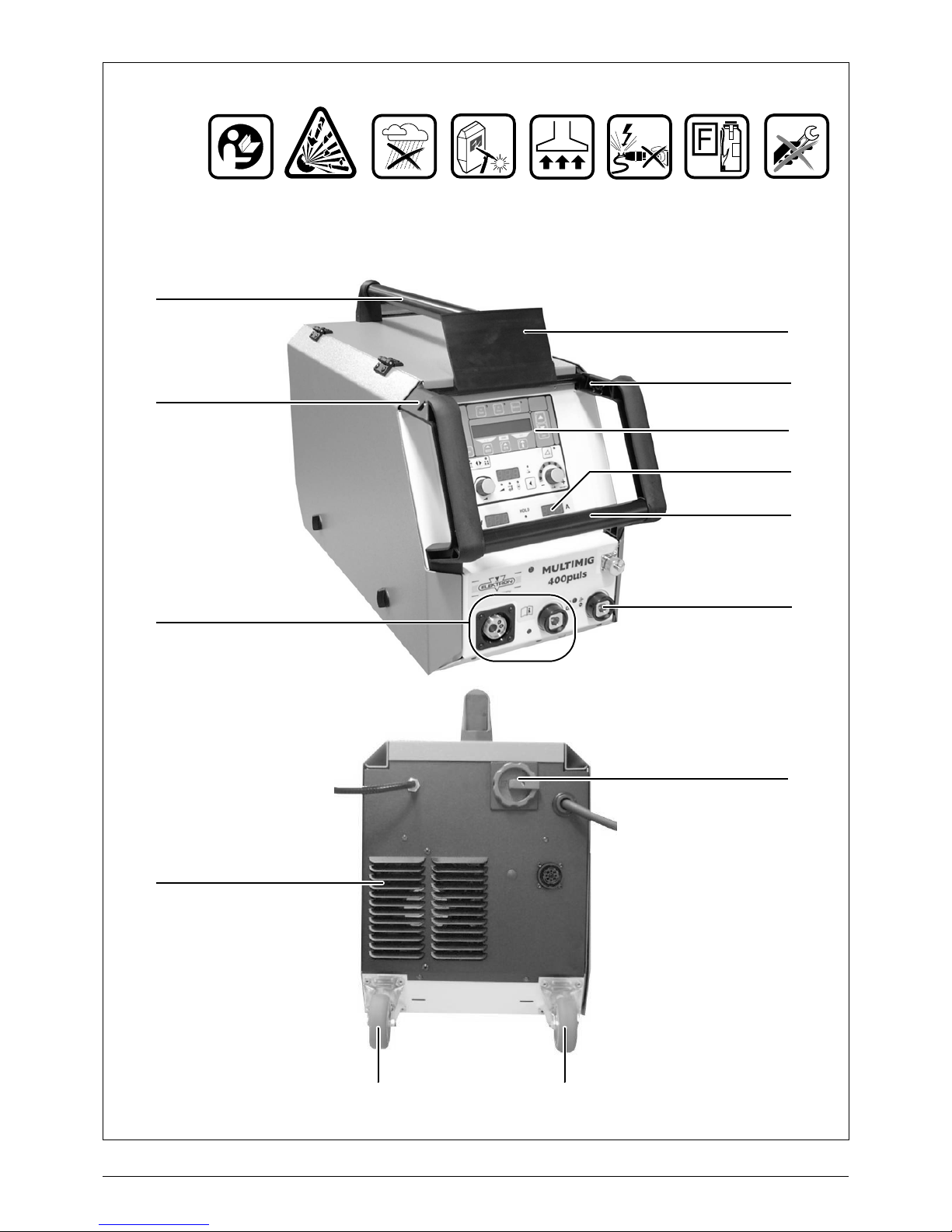
5 Facility for transportation
6 Handle
7 Operating panel
8 Connections
9 Air outlet
10 Transport rollers
11 Main switch
12 Display of welding current and welding voltage
14 Connection socket for ground cable
15 Protective cover, operation panel
This unit is for welding steel, aluminium and their alloys, for
commercial as well as for industrial use.
This unit is protected electronically against overloading.
Close the side lid before welding.
Connect the workpiece with the groundcable to the unit.
Remove welding spatter from the inside of the gas nozzle with
a special pair of pliers. Spray with anti spatter spray inside the
gas nozzle to avoid adherence of spatters. Spray sloping to
avoid the obstruction of the gasoutlet.
At transportation of the unit only use the purposed transportation facilities 5, do not use a fork-lift truck or something similar at the machine case.
1 Safety precautions
GB
S
2 Machine elements
3 General regulation of use
4 Unit protection
Page 4

4
The sound level of the unit is smaller as 70 dB (A) measured
at standard load conforming EN 60
974 at the max. work-
point.
Depending on the operation, users of commercially operated
welding systems are obliged to have safety inspections of the
equipment carried out regularly in accordance with
VDE
0544-207. ELEKTRON recommends inspection periods
of 12 months.
A safety inspection must also be carried out after alterations
or repair of the system.
! Caution ! : Improperly carried out UVV inspections can destroy the system.
For more information on UVV inspections of welding systems,
please contact your authorized service center.
This product is manufactured conform to the current EMV
standard. Please notice following items:
The unit is for welding under commercial or industrial con-
ditions. The use in other surroundings (for example in residential areas) may disturb other electric devices.
During welding electromagnetic problems can be caused
at:
– Mainscables, controlcables, connections for telecom-
munication
–TV / Radio
– Computer and other similar devices
– Protection devises as for example alarm systems
– Pacemakers and hearing aids
– Devices for measure and calibrate
– Devices with less protection against disturbances
If other devices are disturbed it may be necessary to pro-
tect additionally.
The affected area can be bigger than your premises /
property depends of the building etc.
Please use the unit conform to the instructions of the manufacturer. The user is responsible for installation and use of the
machine. Furthermore the user is responsible to eliminate the
disturbances caused by electromagnetic fields.
5 Emission of sound
6 UVV inspection (UVV = regulations
for prevention of accidents)
7 Electromagnetic compatibility (EMV)
8 Technical data
Type MULTIMIG 400puls
Welding
Welding range (I
2min-I2max
/
U
2min-U2max
)
A/V 25 – 320/
15.2 – 30
No load voltage V 81
Voltage adjustment continuously variable
Slope characteristic constant / falling
Duty cycle 100 % 40 °C A 250
Duty cycle 60 % 40 °C A 270
Duty cycle at max. current 40 °C % 35
weldable wire steel Ø mm 0.6 – 1.2
weldable wire alu Ø mm 1.0 – 1.2
welding electrodes Ø mm 1.0 – 6.0
Wire-feed speed m/min 0.1 – 25
Mains
Mains voltage 3~ (50/60 Hz) V 400
Mains voltage tolerance range % +/- 15
Input power S1 (100 %/40 °C) kVA 10.7
Input power S1 (60 %/40 °C) kVA 12.6
Input power S1 (max. current) kVA 15.1
Current input I1 (100 %/40 °C) A 15.5
Current input I1 (60 %/40 °C) A 18.2
Current input I1 (max. current) A 21.8
Power factor (at I
2max
) cos ϕ 0.99
Mains fuse A/tr 16
Mains plug CEE16
Unit
Protection class (EN 60 529) IP23
Insulation class F
Cooling method F
Noise emission dB (A) <70
Page 5

5
)
Please refer to chapter 10 “Before operation” and
chapter 11 “Setting into operation” for a full description.
Place gas cylinder 3 on machine and secure with safety
chain 35.
Remove screw cap from gas cylinder and open gas cylin-
der valve 34 briefly (blow-off).
Connect pressure reducer 2 to gas cylinder.
Connect gas hose 31 from machine to pressure reducer
and open gas cylinder.
Plug mains plug in socket.
Connect ground cable 22 to ground connection 14 (–) and
attach ground clamp 13 to workpiece.
Insert wire feed roller 29 to wire feeder to fit welding wire
selected, set contact pressure to position 2.
Connect torch 1 (central socket 16, water connections 20
red-blue) and mount contact tip to fit welding wire selected.
Insert welding wire.
Turn on main switch 11.
Press push-button 51 and push-button 48 (gas type)
(solenoid valve is activated) and adjust gas amount on the
pressure reducer
(rule of thumb: wire diameter x 10 = gas flow).
Keep the wire insert switch pressed until the welding
wire protrudes approx. 10 mm out of the gas nozzle on the
torch neck.
Select welding material by pressing button 44.
Select wire diameter by pressing button 46.
Select shielding gas type by pressing button 48.
Select 2-stroke mode by pressing button 52.
Press push-button 56 until the center LED for material
thickness lights up and adjust the thickness of the material
to be welded with the rotary pulse encoder 53.
Hold down torch button to weld.
Release torch button to stop welding process.
If required, the arc length can be corrected with the rotary
pulse encoder 58.
Dimensions and weights
Dimension power source (LxWxH) mm 745x340x498
Weight of power source A vers. kg 35
Standard equipment
Wire feed unit Rollers 4
Wire diameter mm 1.0/1.2
Torch type
ML 2400 PM
9 Short instructions
Type MULTIMIG 400puls
Page 6
6
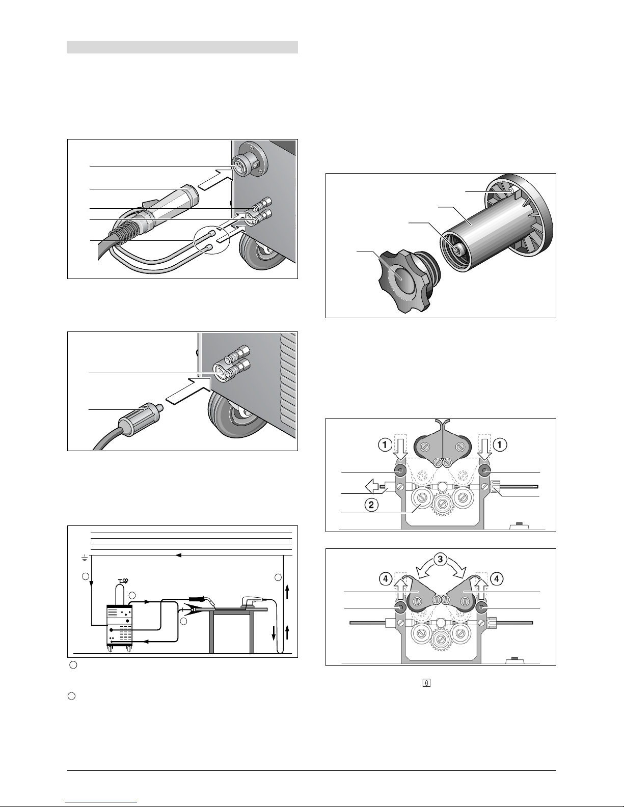
Torch connection
Plug in the centralplug 17 of the torch 1 into the central socket
16. At machines with water-cooling: Connect additionally the
waterconnections 20 of the torch with the sockets 18 and 19.
Please keep attention at the colour labelling.
Red = water back-run 19
Blue = water fore-run 18
How to connect the ground cable
Connect the ground cable 22 at the groundconnection 14 and
fasten it turning to right and connect the ground clamp 13 to
the workpiece or at the welding table.
How to connect the ground clamp
Fasten the ground clamp 13 near the welding location, this
avoids that the current will flow trough machineparts or con
-
trols.
Please keep attention that the connections between ground
clamp and workpiece is constant.
Do not place the ground clamp on the welding machine or
gas cylinder, otherwise welding current is conducted via
the protective conductors and will destroy them.
Connect the ground clamp tightly to the welding bench or
to the workpiece.
How to connect at the mains
Plug in the plug into the mains socket. The fusing should be
corresponding to the technical data.
How to insert the wirespool
Open the lid at the machine or at the wire-feed case 2 and
screw off the nut 26 from the wire-coil pick-up 24.
Put on the wire coil at the wire-coil pick-up and pay attention
that the tappet is well insert at the coil 23.
By use of small wire coils please use the adapter.
Adjust the brake 25 by releasing the torch button the wire coil
do not continue to turn.
Insert of the wire electrode
Screw out the contact tip at the torch 1.
Open the lid at the unit or at the wire feeder 2.
The diameter of the wire should correspond to the diameter of
the feeding rolls. This is readable on the front at the built in
feeding roll 29.
Lift the lever 27 and thread in the wire electrode trough the inlet nozzle 28 and the central connection 16.
Close the lever 30 and fasten it with the sweep levers 27.
Switch on machine at main switch 11, stretch torch cable and
press button wire insert
on operating panel. Adjust the
pressure at the modulation screws 27 that the wire-feed rolls
29 even still are turning by holding the wire coil. The wire
should not be clamped or deformed.
10 Before operation
16
17
18
19
20
14
22
2
1
1
L1(R)
L
2
(S)
L
3
(T)
N(MP)
PE
1
1
2
23
24
25
26
29
27
28
16
27
30 30
27
27
Page 7

7
Indication for 4 rolls feeding units: Adjust the pressure of the
wire rolls 29 at the side of the inlet nozzle 28 less then at the
side of the central connection 16, this provides that the wire
will be hold correct in the wire-feed unit.
Press the button wire insert till the wire appears approx.
20 mm out of the torchneck.
Screw in the contact tip corresponding to the wirediameter
and cut off the sticked out wire end.
How to connect the gas cylinder
Put the gas cylinder 3 on the provided place at the back of the
machine and protect against falling by fastening the chain 35.
Open the gas valve 34 several times to blow out possible dirt
particles.
Connect the pressure reducer 2 at the gas cylinder 3. Con-
nect the gas hose 31 at the pressure reducer. Open the gascylinder and adjust the gas flow at the set screw 36 of the
pressure reducer while pressing the torch button. The quanti
ty will be shown at the flowmeter 32. This should be approx.
wire diameter x 10
l/min. The content of the cylinder is shown
by the contentmanometer 33.
How to modify the machine for aluminium
welding
Change the wire roll to a aluminium wire roll.
Change the steel-torch against an aluminiumtorch or resp.
change the wire liner against a teflon liner.
Remove the capillary tube 42 at the central connection.
Cut the teflon liner close to the end of the wire-feeding roll and
pull the brasstube over the teflon liner with the corresponding
length for stabilising it.
Fasten the torch and thread in the wire electrode.
)
The art.no. of the parts depends on the torch and wirediameter. Please see at the torch spare list.
17 Centralconnection
38 Nipple for 4.0 mm and 4.7 external diameter
39 O-ring 3,5 x 1.5 mm to prevent gas outlet
40 Nut
41 Teflon and plastic liner
42 Sustainpipe for teflon and plastic liner with 4 mm exter-
nal diameter it substitute the capillary pipe in the central
connection.
At 4,7 mm no sustainpipe is required.
29 Wire-feed roll
p p p
correct contact
pressure too
high
wrong
wire-feed
roll
34
3
35
2
31
33
32
36
17 38 39 40 41 42 29
Page 8

8
DP 20 operating panel
43 “Mode” push-button
For switching between the operation modes Normal,
Pulse, TwinPulse and Electrode.
44 “Material” push-button
For selection of the material to be welded. The push-button is also used for the “Decrementing” (-) function, e. g.,
to reduce the value of a secondary parameter.
45 “TT Save” push-button (Tiptronic)
For storage of a job.
46 “Welding wire diameter” push-button
For diameter selection of the wire to be welded. The
push-button is also used for the “End” function, with
which you can switch back to the display of the previous
menu level.
47 “TT Enter” push-button (Tiptronic)
For acknowledgement when saving a job.
48 “Gas type” push-button
For selection of the gas to be used. The push-button is
also used for the “increment” (+) function, e.
g., to in-
crease the value of a secondary parameter.
49 “Tiptronic” push-button
For switching the Tiptronic mode on or off.
50 Multi-function display
For indication of all parameter values and messages.
51 and push-buttons (Enter)
For switching between the individual secondary parameters. Pressing both push-buttons at the same time is
used for acknowledgement (Enter).
52 “2-stroke / 4-stroke” push-button
For switching between 2-stroke and 4-stroke operation
mode. A lit LED indicates the currently selected operat
-
ing mode.
53 Rotary pulse encoder for welding current / material thick-
ness
The rotary pulse encoder is used for adjustment of the
required welding current and material thickness. The adjustment range can be limited, depending on the selected material-wire-gas combination.
54 Digital multifunction display
For indication of the primary parameters such as welding
current, material thickness (in mm), wire feed speed (in
m/min) or arc length correction.
55 “Primary parameter” LEDs
These show which primary parameter is currently indicated in the multifunction display 54.
56 “Primary parameter” push-button
For switching between welding current, material thickness, wire feed speed and arc length, as indicated in the
digital multifunction display 54.
57 “Downslope” push-button
Switches the downslope function on or off. A lit LED next
to the push-button indicates that the downslope is on.
58 “Arc length / wire speed correction” rotary pulse encoder
For correction of the arc length or wire speed (dependent on setting menu extra “arc lenght control“). Up to +/40 % of the characteristic value can be corrected.
59 “Arc length / wire speed correction” LED indication
Indicates the degree of the correction. When the uppermost center LED is lit, the programmed arc length/wire
speed remains unchanged; “0” is indicated in the multifunction display 54. Turn the rotary pulse encoder 58 left
to reduce the arc length/wire speed; turn the rotary pulse
encoder 58 right to enlarge the arc length/wire speed
.
60 Torch display
Indicates the current welding power, material thickness,
wire feed speed or arc length correction (identical with
the digital multifunction display 54). In Tiptronic mode,
the current job set and the current job number are indi
-
cated.
61 Torch rocker
For changing the welding power, material thickness or
arc length (depending on which value is being indicated
in the digital multifunction display 54).
In Tiptronic mode, the rocker can be used to switch between the active jobs or job sets.
62 Torch “Modus” push-button
Has the same function as the “Primary parameter” pushbutton 56 on the DP20 operation panel.
In Tiptronic mode this push-button can be used to switch
between job selection and job-set selection.
Current / voltage display
The actual welding voltage and welding current values are indicated during the welding. After the welding procedure, the
“Hold” LED lights up and the last welding voltage and welding
current values are indicated. When the operator changes certain welding adjustments (e. g. level, program, job), the “Hold”
LED goes out and the reference values for current and volt
-
age are indicated.
11 Setting into operation
TT
Save
Enter
Tiptronic
(END) (+)
TT
Enter
Mode
mm
43 44 45 46 47 48 49 50 51
52 53 54 55 56 57 58 59
60
62
61
Page 9

9
12 Menu Structure
Main Level Level 1 Level 2 Remark
Gas pre-flow 0 – 10 sec.; not in electrode mode
Start current 20 % – 200 % of the welding current
Start current time 0 – 10 sec.; not in 4-stroke mode
Twin pulse frequency 0,5 – 5 Hz; only in Twinpulse mode
Twin pulse current change 5 – 50 % of the welding current; only in Twinpulse mode
Twin pulse relation 20 % – 80 %; only in Twinpulse mode
Welding current Adjustment range depends on the selected material-wire-
gas combination
Downslope 10 – 990 A/sec.; not in electrode mode, only when downs-
lope = on
Final current 10 % – 100 % of the welding current; not in electrode mode,
only when slope = on or in 4-stroke
Final current time 0 – 10 sec.; not in electrode mode, only for slope = on
Wire burnback time 20 % – 300 % of the programmed value; not in electrode
mode
Gas post-flow 20 % – 200 % of the programmed value; not in electrode
mode
Arc length correction 60 % – 140 % of the programmed value
Inductor effect 20 % – 200 % of the programmed value; only in normal
mode (short arc)
+/- 40% in manual mode (see “Manual mode” on page 11)
Arc dynamic 0 % – 100 % of the programmed value; only in electrode
mode
Job selection, indication of
set and job name
Set and job name are indicated only in Tiptronic mode
upon actuation of the “TT Enter” push-button 47 or the “Tiptronic” push-button 49
Edit mode for set and
job name
Move the cursor with the and push-buttons 51;
change the character with the pushbuttons 48 (+) and 44 ()
Extras 1Machine data Operating system Master Version number, operating system Master
Operating system Process Version number, operating system process
Operating system DMRs Version number, motor assembly (-ies)
Welding program version Version number, welding programs
Operating hour counter Indication of the welding duration in h, min, sec
Configuration Machine type and the recognized power module (with max.
current ) are indicated alternately
2 Diagnosis Last error message Indication of the last three error messages from the error
memory (0 = last error, 2 = oldest error)
Module temperatures Temperatures of the power modules in °C
Operating voltages Indication of the operating voltages (15 V / 24 V) of the
E-assembly DP-MAPRO
Flow rate, cooling unit Indication of the coolant flow rate in l/min
3 Language Selection of the menu language
4 Display contrast Contrast setting of the LCD display
5 Mode cooling system 0 normal cooling unit switches on, as soon as an arc is ignited
1 on cooling unit runs constantly
2 off cooling unit is deactivated
6 Lock function 0 All free
1 Welding current, mode and Tiptronic on/off free
2 Tiptronic on/off, job selection free
3 All locked except menu selection, gas and pump test
7 Arc lenght control voltage correct arc lenght with rotary pulse encoder 58
wire correct wire speed with rotary pulse encoder 58
8 Robot interface Menu item is only visible when the machine is equipped
with a robot interface (further details about setup/configura
-
tion see operation manual INT)
Page 10

10
Menu structure
Secondary parameters (menu main level)
With the and 51 push-buttons you can switch between
the secondary parameters. The currently selected parameter
is indicated in the display 50. The value in the square brackets
is a standard or suggested value.
Push-button 44 (-) is used to reduce the indicated parameter
and push-button 48 (+) is used to increase the value of the in
dicated parameter. By actuating the push-button 46 (END)
the system switches back to the material-wire-gas combina
tion display.
Extras menu
In addition to the secondary parameters, the Extras menu
item is also available; it offers the following functions:
Push-buttons 44 (-) and 48 (+) are used to switch between the
menu items. The different entries of the menu items are called
up by pressing the
und push-buttons 51 at the same
time. Switching between the individual entries is also possible
here with the push-buttons 44 (-) and 48 (+). To return, press
push-button 46 (END).
Tiptronic
The Tiptronic function provides you with 100 independent
jobs (10 job set with 10 jobs each). A job stores all the settings
and corrections on the operating panel.
The best way to use the Tiptronic function is to assign job
numbers to frequently recurring welding tasks or save the set
-
tings which individual welders use specifically for “their” jobs.
Programming jobs:
Determine the optimal welding adjustment.
Press the “TT Save” button 45 (Save LED flashes).
Select the target job number with the push-buttons 44 (-)
and 48 (+) or with the torch rocker, and confirm with the
“TT Enter” push-button 47 (if you do not press Enter, the
Save LED goes out after 10 s after the last keystroke and
the save operation is aborted).
The Save and Enter LEDs flash briefly to confirm that pro-
gramming is terminated.
Twin pulse relation
Welding current
Downslope
Twin pulse current change
Twin pulse frequency
Start current time
Start current
Gas pre-flow
Job selection
Extras
Arc dynamic
Inductor effect
Gas post-flow
Wire burnback time
Final current
Last error messages
Module temperatures
Operating voltages
Configuration
Operating hour counter
Welding programs
Operating system Process
Operating system Master
0 normal
1 on
select language
flow rate cooling system
2 off
2 Diagnosis
1 Machine data
5 Mode cooling system
6 Lock function
4 Display contrast
3 Language
7 Arc lenght control
11 Robot interface
3
2
1
0
Voltage
Wire
change between
parameters with
keys 51
enter menuitem by pressing both keys 51 at the
same time
change between menuitems with keys 48
(+) und 44 (-)
Final current time
Arc lenght correction
Operating system DMR
Page 11

11
Selecting jobs:
Switch the Tiptronic function on by pressing “Tiptronic” 49
(associated LED comes on).
Select the job number with the torch rocker (alternatively
the job number can be selected with the push-buttons 44
(-) and 48 (+)).
To exit the Tiptronic mode, press “Tiptronic” 49 (Tiptronic
LED goes out). The parameters are reset to the values
that existed before you switched on the Tiptronic mode.
Setting a job inactive:
Switch the Tiptronic function on by pressing “Tiptronic” 49
(associated LED comes on).
Select job number with the torch rocker 61 or with the
push-buttons 44 (-) and 48 (+) (an active job is indicated
in the torch display 60 and in digital multifunction display
54 with a decimal point between the job set and the job
number).
Hold the Enter push-button 47 pressed for two seconds
(the decimal point in the torch display 60 and in the digital
display 54 goes out).
Setting a job active:
Switch the Tiptronic function on by pressing “Tiptronic” 49
(associated LED comes on).
Select the job number with the push-buttons 44 (-) and 48
(+) (with an inactive job, the decimal point between job set
and job number is missing).
Hold the “TT Enter” push-button 47 pressed for two sec-
onds (the decimal point between the job set and the job
number lights up).
Reprogramming jobs:
Switch the Tiptronic function on by pressing „Tiptronic“ 49
and select a job (see Selecting Jobs).
Change the settings as required.
Press the “TT Save” button 45 (Save LED flashes).
Press “TT Enter” button 47 to confirm.
The Save and Enter LEDs flash briefly to confirm that pro-
gramming is terminated.
Copying jobs:
Switch the Tiptronic function on by pressing “Tiptronic” 49
and select a job for copying (see Selecting Jobs).
Press the “TT Save” button 45 (Save LED flashes).
Select the target job number with the push-buttons 44 (-)
and 48 (+) and confirm with the “TT Enter” push-button 47
(if the Enter push-button is not actuated, the Save LED
goes out 10 seconds after the last push-button actuation
and the saving procedure is cancelled). If the target job
number has not been occupied with a job yet, it will be in
-
dicated flashing in the display.
The Save and Enter LEDs flash briefly to confirm that pro-
gramming is terminated.
The user-defined job texts are also copied onto the new
target job number.
Assigning job texts
An individual text can be assigned to each job in order to specially mark it or allocate it more clearly.
Switch on the Tiptronic function with the “Tiptronic” push-
button 49.
Select the job number with the push-buttons 44 (-) and 48
(+).
Press the and push-buttons 51 at the same time (a
flashing cursor appears in the display 50) in order to get
into the edit mode.
The cursor is moved with the and push-buttons 51.
At the end of the line, the cursor jumps to the respective
next line.
Select a character (number, letter or special character)
with push-buttons 44 (-) and 48 (+).
The edit mode is ended by pressing push-button 46 (END)
or by pressing the and push-buttons 51 at the same
time.
If you press the “Tiptronic” push-button 49 in edit mode
(Tiptronic is switched off), then the text entries will not be
saved.
Texts can be programmed both for the job set (upper line in
display 50) as well as for the job (bottom line in display 50).
Special functions
Gas test
Pressing the push-button 51 and the “Gas type” push-but-
ton 48 at the same time activates the gas test function. The
solenoid valve of the system is activated and the gas supply
can be checked
/ adjusted. The function remains active for 30
seconds and is then ended automatically. By pushing the
“Gas type” push-button 48 again, the gas test can be terminated prematurely.
Pump test
Pressing the push-button 51 and the “Material” push-button 44 at the same time activates the pump test function. The
water pump is switched on and runs for approx. one minute.
By pushing the “Material” push-button 44, the pump test can
be terminated prematurely.
Resetting adjustments
Pressing the push-button 51 and the “TT Enter” push-button 47 at the same time resets all secondary parameters to
the suggested values. When the Tiptronic mode is active, the
settings of the current job are reset. All adjustment in the Ex
tras menu (language, display contrast, etc.) remain unchanged.
Manual mode
In manual mode the machine can weld independently from a
characteristic. Only welding voltage and wire feed speed are
set separately:
switch to manual mode with button 43
set welding voltage (10V - 40V) with knob 53
set wire feed speed (0,5 - 25 m/min) with knob 58
The following parameters are available in manual mode:
– inductor effect (+/- 40%, select with button 56, LED arc
lenght 55 is lit)
– wire insert speed (0,5-15 m/min)
– gas pre-flow (0-10 sec.)
– wire burnback time (5-300%)
– gas post flow (20-300%)
Page 12

12
Error codes
In case of a malfunction, an error code is indicated on the digital multifunction display 54 and the corresponding error description
appears on the LCD display 50. As long as an error code is indicated, welding operation is not possible.
Code lock function
The lock function in menu Extras is secured with a code lock. A three-digit code must be entered before the lock function can be
changed. Only after the correct code is entered, the lock function can be altered. After leving the menu, a new code number can
be set or the old code number is acknowledged. Code "000" is the default (factory setting) number.
Procedure:
switch to menu Extras, lock function
pressing button 44 (minus) or 48 (plus) question „change parameter ?“ is displayed
acknowledge with button 51 (up)
set three-digit code number with button 44 (minus), 48 (plus) or encoder 53
acknowledge the code number with button 51 (up)
set desired lock function number with buttons 44 (minus) or 48 (plus)
leave menu with button 46 (END)
if requested, set a new code number with buttons 44 (minus), 48 (plus) or encoder 53
acknowledge the code number with button 51 (up)
Code Error description Remark Remedy
E00 no Prog No welding parameters for the selected
material-wire-gas combination (no sensible
combination)
Choose a different material-wire-gas
combination
E01 Thermal overload The system has been overheated Allow the system to cool down in standby;
check the ventilation
E02 Mains overvoltage Mains voltage too high Check mains voltage
E03 Overcurrent Output current too high Notify service technician
E04 Air-cooling error Flow rate of air too low Clean the air intake 9; check fan
E05 Faulty cooling circuit No or too little flow rate of water Check level of cooling liquid and coolant filter
E06 Overvoltage Output voltage too high Notify service
E07 EEProm checksum error Adjustment data faulty or not available Switch system off and then on again
E08 Wire feed / tacho Current input from feed motor too high
No tacho signal available
Blow out torch package with compressed air
and check wire feed unit
E09 Error v/a measuring Faulty current / voltage measuring systems Notify service
E10 Torch socket / cable Faulty torch switch cable or torch switch
socket
Check torch
E11 Remote control socket Faulty remote control or socket of remote
control
Check remote control
E12 Communication process Defective communication CAN-Bus (process) Switch system off and then on again
E13 Error, temperature sensor Thermo sensor not operative Notify service
E14 Supply voltage Internal supply voltage too low Check mains voltages
E16 Overcurrent protection 1 Allowable maximum power supply of power
unit 1 too high
Notify service
E18 Overload protection Safety switch device for protection of
electrical components
Allow the system to cool down in standby
E20 Overvoltage secondary Output voltage too high Notify service
E21 Output voltage / current Power unit delivers voltage / current without
drive
Notify service
E22 Mains undervoltage 1 Mains voltage at power unit 1 too low Check mains voltages
E23 Mains overvoltage Mains voltage too high Check mains voltages
E24 Overcurrent protection 2 Power supply of power unit 2 too high Notify service
E25 Power-module detection Power unit not being recognized or unallowa-
ble combination of power units
Notify service
E27 No program (DSP) Welding programs faulty or not available Notify service
E30 Mains undervoltage 2 Mains voltage at power unit 2 too low Check mains voltages
E31 Communication error Faulty communication CAN-Bus (master) Switch system off and then on again
Page 13

13
Principle of the MIG / MAG welding
The welding wire is fed from the wire coil to the contact tip due
to the wire-feeding rolls. The arc burns between the melting
wire electrode and the workpiece. The welding wire acts as
arc carrier and filler material. Shielding gas flows through the
gas nozzle and protects the arc against the atmospheregas.
At metal shielded gas welding both, inert and active gases are
used. The distinction is made between Metal Inert Gas (MIG)
and Metal Active Gas (MAG) welding.
Further possible classification is by the type of arc. This
means the external form of the arc, is proneness to shortcircuiting, and the way of transfer to the workpiece.
It is not possible to select the arc force to each individual
welding process. This is only limited possible for example at
the short circuiting arc. The mode of material transfer can be
selected at all types of gas shielded metal arc welding by
choosing the suitable current and the corresponding arc volt
age, although the short circuit frequency and the size of the
drops depends from the type of shielded gas used.
Types of arc
Short circuit arc
This type of arc is specially suitable for thin materials and positional welding due to a relative cool welding pool welded
with very short arc, low arc voltage and low current. The sur
face tension of the welding pool helps to draw the drop into
the bath and to reignite the arc. This cycle is repeated again
and again so the short circuit and the arcing period is constantly alternating.
)
The transition from the short circuit to spray arc depends on the wire diameter and the gas mixture.
Transitional arc
The transitional arc is especially suitable for medium thickness sheet metals and for vertical-down welding. The transfer
of the electrode to the workpiece takes place partly in short
circuit and in free flight. Due to less short circuiting the welding pool is hotter than at the short circuit arc. Welding with
transitional arc provides higher electrode melt rate and is
more economic than welding at short circuit arc.
Long arc
Long arcs are typical at welding at the higher ampere range
under carbondioxid and gases with a high CO
2
content. It is
not particularly suitable for positional welding. In this type of
arc large drops are formed which falls into the welding pool
mainly by force of gravity. Due to that short circuits occasion
ally occur, which by the increase of the current at the moment
of the short circuiting lead to spattering when the arc is reignit
ed.
Spray arc
The spray arc is not suitable for positional welding, due to the
extremely liquid nature of the welding pool. The spraying arc
forms by welding at the higher range of ampere using inert
gas or mixtures with high argon content. The most typical
characteristic of the spray arc is the short circuit free transfer
of extremely fine droplets.
Working range at MAG welding
13 Basic of the MIG / MAG welding
process
Welding
process
Shielded gas
inert active
MIG Helium (He)
Argon (Ar)
Mixtures of
Ar/He
MAG-C Carbon dioxide
100
% CO
2
MAG-M Mixtures of
Ar/CO
2
Ar/O
2
Arc
Contact tip
Gas nozzle
Wire electrode
Wire-feed rolls
Power source
Workpiece
Shielding gas
Welding seam
Wire diameter
Long arc /
Spray arc
Transitional
arc
Short
circuit arc
mm A V A V A V
0.8 140…
180
23… 28110…
150
18… 2250…
130
14…
18
1.0 180…
250
24… 30130…
200
18… 2470…
160
16…
19
1.2 220…
320
25… 32170…
250
19… 26120…
200
17…
20
1.6 260…
320
26… 34200…
300
22… 28150…
200
18…
21
Favourable welding characteristic are only possible if voltage and
current are correctly adjusted.
CO2 requires an arc voltage approx. 3 V higher than gas mixtures
with a high argon content.
Page 14

14
Holding and manipulating the torch
)
Metal shielded gas welding can be welded in all positions: horizontal, vertical-down, vertical-up, overhead
and in horizontal-vertical position.
At horizontal welding hold the torch vertical to the workpiece
(neutral torch position) or up to 30° “pushing” the torch. At
thicker welds, a slight dragging motion is sometimes used.
For best depth of penetration and covering of shielded gas is
the neutral position of the torch the most suitable one. Please
notice if the torch is tilted to far, it could be that possible that
air will be sucked into the shielded gas atmosphere (injection
effect).
At vertical and overhead welding a slight pushing motion is required. Vertical down welding is most used for thin materials,
for this kind of weld hold the torch at the neutral or slightly
“dragging” position. For this kind of welding is some experi
ence required cause the welding pool could run ahead and
cause some lacks welding. With thicker material there is a
danger of lacks of fusion cause the welding pool is very liquid
due to high voltage.
Avoid extreme side to side movements to avoid that the welding pool will be damed up in front of the arc. This could cause
lacks of fusion due to the welding pool flows ahead of the
welding spot. The side to side motion should only be as wide
as is necessary to reach both sides of the joint. If the joint is
wide enough you should weld two parallel string beads.
At vertical-up position the side to side motion should describe
the shape of an open triangle.
Length of the arc
Welding with a longer arc reduces the penetration, the welding bead is wide and flat with increased spattering. The welding material is transferred with slightly larger drops than at
welding with a shorter arc. A longer arc is useful for welding a
fillet weld to form a flat or concave seam.
Welding with a shorter arc (at the same amperage) increases
the penetration, the welding bead is narrow and high with re
duced spattering. The welding material is transferred with
smaller drops as long as the welder is not welding with short
arc.
Length of the wire electrode
The distance between the torch and the workpiece should be
10 – 12 times the diameter of the wire. Altering the distance
of the torch will influence the length of the electrode end.
A longer electrode end reduces the amperage and the penetration.
A shorter electrode end increases the amperage if the wirefeed speed remains the same.
Current and voltage pulses
Material transfer is achieved by current and voltage pulses
controlled at the same rate as the pulse frequency. The arc
power is changed by the ratio between basic and current
pulses, the pulse duty factor between basic and current puls
-
es and the pulse frequency.
Welding direction draggingWelding direction pushing
Long arc
Short arc
14 Basics of pulsed arc welding
Long electrode end
Short electrode end
U
g
us[v]
U
mUp
l
g
t
g
Tp = 1/ f
p
k
ritische Stromstärke
t
p
is[A]
t[s]
t[s]
l
mlp
Page 15

15
Material transfer
Benefits:
– Controlled, short-circuit-proof material transfer without
spatter
– Low thermal transfer due to low primary current
Disadvantages:
– Special units with large number of setting parameters
required
– Only shielding gases without or with low CO2 content
Forces acting during material transfer
The amount of heat required to melt the wire electrode results
from arc power and resistance heat build-up in the free wire
end.
A number of forces come into play in the resulting drop formation and separation.
)
The main force components for separating the drops are
electromagnetic forces (pinch effect).
Welding parameters
Pulse period t
P
The pulse period for separating the drop should be between
1.5 and 3.0 ms depending on wire diameter and the pulse cur
rent setting IP.
If the pulse period is too long, material transfer only takes
place during the pulse phase.
Arc formation and drop rate can be affected by additional
pulse stages.
Pulse voltage UP and pulse current I
P
Since welding with pulsed arc is based on the temporary utilisation of the pinch effect, the drop-separating pulse current
must always be large enough to exceed critical current inten
sity depending on wire diameter, wire material and shielding
gas composition, etc. If this value is not achieved, material
transfer takes place completely or partially in the short circuit
with possible spatter.
Wire feed speed vD and pulse frequency f
P
The main condition for a controlled material transfer with one
drop per pulse is to set a defined drop volume. The volume of
the melted drop must then be identical with the volume of the
wire electrode fed in each pulse period. The necessary wire
feed speed v
D
results from the product of pulse frequency f
P
and the wire length l melted in each pulse period. From this
relationship you see that a change in wire feed speed re
quires a linear change in pulse frequency. A rise in electrode
melt rate by increasing wire feed speed therefore needs a
higher pulse frequency. The objective drop diameter should
be about 1.2
mm with a wire diameter of 1.2 mm.
Primary current
Arc length ionisation must be maintained during the primary
current phase, whose period results from the selected fre
quency and pulse period. This requires currents ranging between 25 and 80 A depending on wire diameter, material and
material thickness. The primary current can also be used to
affect the arc and material transfer. At a constant ratio of wire
feed speed and pulse frequency, the arc length can be
changed by varying the primary current and the associated
voltage. Reducing the primary current causes a shorter arc.
This can be used to counteract arc deflection with fillet welds
or at high welding rates.
The time of drop separation can be affected by varying the ratio of primary current to pulse current. Normally the objective
is to separate the drop just after the current pulse in the pri
mary current phase (on the Saprom 900, in the third pulse
current phase). This can be achieved by increasing the prima
ry current and reducing the pulse current at the same time.
Remember that excessively high primary current will melt the
free wire end too quickly. This will form very large drops which
can lead to spatter during the transition to the welding pool.
Electrostatic
Forces
Workpiece
Surface
tension S
Acceleration due
Electromagnetic force
FL (pinch effect)
Eddying forces
caused by
Forces of
repulsion (F
R
) of
evaporating
Force of inertia
Constrict drops
Viscosity
Wire electrode
to gravity
material
plasma flow
Page 16

16
Pulsed arc applications
The main application for pulsed arcs is unalloyed steels within
the performance range of the transition arc. At the lower end
of the performance range the pulsed arc cannot fully replace
the short-circuiting arc. The reason here is the continuous arc
that occurs in the primary current phase. This phenomenon
does not exist with the short-circuiting arc. An exception to
this is when welding aluminium and aluminium alloys. Nor
mally, these materials can only be reliably welded using a
pulsed arc. In the upper performance range, the pulsed arc is
preferable to the sprayer arc, in particular for welding aluminium materials and high-alloy steels.
Please keep attention to the current safety regulations at all
care and maintenance works.
The machine requires minimum of care and maintenance.
Only a few items should be checked to ensure a trouble free
long term operation:
– Check the mains plug, mains cable, and the welding
torch as well as the ground connection for damage from
time to time.
– Once or twice a year please clean the machine with dry
low compressed air. Switch off the machine and pull out
the plug first. Open the case of the machine and clean
also inside - please avoid to blow directly onto electronic
parts – they could be damaged.
15 Care and maintenance
16 Troubleshooting guide
Symptom Cause Remedy
Torch too hot Insufficient coolant through flow due to pollution into
coolant
Swill the waterhoses of the torch in opposite
direction
Contact tip is not tight Check it
No function when torch
button is pressed
Nut of the torch hose is not tight Tighten it
No connection of the control cable in the torch hose Check and change if necessary
Overload of the unit and thermal protection is in
function
Allow unit to cool down at no load
Irregular wire feeding or
wire welds to the con
-
tact tip
Wire electrode is tight at the spool Check and change if necessary
Burr at the wire beginning Cut the wire beginning again
Irregular wire feeding or
no wire feeding
Wrong contact pressure at the wire-feed rolls Adjust it as described in the manual
Torch defect Check and change if necessary
No brass pipe in the central connection or is dirty Install or clean the brass pipe
Bad quality of welding wire Check and change if necessary
Rust formation at the welding wire Check and change if necessary
Torch liner is dirty inside Disconnect the torch from the machine, screw
off the contact tip and clean the liner with com
-
pressed air
Torch liner is dejected Check and change if necessary
Motor brake adjusted to strong Adjust as described in the manual
Unit switches off Duty cycle overloaded Allow the machine to cool down
To less cooling of unit parts Check the air in and outlet
Cooler or hoses defect
or pump is damaged
Freezed systems due to less anti freezer liquid Contact the nearest service facility
Arc or short circuit
between contact tip
and gas nozzle
Spatter built up inside the gas nozzle Remove it with special pliers
Unstable arc Wrong diameter of contact tip or worn out Change contact tip
The DP20 operating
panel is completely dark
Phase missing Check the unit at another power outlet. Check
power cable and mains fuses/circuit breakers
No shielded gas Gas cylinder empty Replace it
Defect torch Check and replace it
Pressure reducer dirty or defect Check and replace it
Valve of gas cylinder defect Replace the gas cylinder
Shielded gas switches
not off
Valve of gas cylinder dirty or does not close Remove torch and pressure reducer and clean
it with compressed air
Not sufficient shielded
gas
Wrong adjusted quantity of shielded gas Adjust right as described in the manual
Dirty pressure reducer Check valve
Torch, gashose blocked or not air-tight Check and change if necessary
Shielded gas is blow away from draught Avoid draught
Page 17

17
UD remote control RC 20
For correctional adjustments of the wire feed speed, level and
job with the RC
20 UD remote control.
Manual control unit HR911
Incl. 5 m power supply cable and CAN-BUS plug. In conjunction with wire feeders without operation panel or Robko wire
feeder, the HR911 must be used as operating panel.
Robot interface INT
Interface for connection to automated welding appliances or
welding robots.
Push pull set
For control of a push pull torch.
Push pull torch
At longer torches as 5 m it is recommended to use a Push pull
torch. Due to an additional wire-feed motor at the torch a con
-
tinuous wire feed is provided.
Wire-feed variations
Precise 4 rolls wire-feed unit for all applications
Less welding
performance
Phase missing Check the unit at another power outlet. Check
power cable and mains fuses/circuit breakers
Poor ground connection Ensure best contact between ground clamp
and workpiece
Ground cable not right plugged in Fasten ground cable by turning the plug to the
right
Defect torch Repair or replace it
Hot plug of ground
cable
Plug was not tightened by turning to the right Check
Higher wire wear out at
wire-feeding unit
Wire rolls does not fit to the wire diameter Install right wire rolls
Wrong contact pressure at wire feeding Adjust as described at the manual
17 Options
Symptom Cause Remedy
Table of variations Use
Roll
alu
Roll
steel
Roll
knurled
Standard Standard at 4 rolls feeding units. Due to the straightening effect of
the roll less wire friction in the torch. For use with thicker or hard
wires.
Knurled rolls ideal for flux cored wires.
Double drive
(special
accessory)
Straightening effect and double drive. Less contact pressure due to
double drive provides less wire disshapes. For use with ticker and
hard wires resp. at longer torch hoses.
Knurled rolls ideal for flux cored wires.
Wire-feed rolls
with grooves
above and
below
(special
accessory)
Rolls with double groove (above and below). No wire disshape.
Ideal for soft wires (Aluminium, bronze, copper,...).
Page 18

18
ELEKTRON-Bremen GmbH
Postfach 10 59 60
D-28059 Bremen
Germany
Telefon: +49(0)421 54 90 6-0
Telefax: +49(0)421 54 90 6-19
Subject to change
18 Service
Page 19

19
Appendix - mounting torch holder
Page 20

326601 06/05
 Loading...