

Page 1
Made in Ge r m a ny
Operation Manual
MULTIMIG 200
MIG / MAG - Welding machine
Item-No: 327 973
Revision: 1.0 - Original
Version: 31.01.2013
Be sure you have read and understood this operating
manual before you carry out any works on and/or with this
equipment!
Page 2

© BlitzRotary GmbH
Branch Bremen
Hinterm Sielhof 22
D-28277 Bremen
Germany
Phone: +49 (0)421 / 54 90 6 - 906
Fax: +49 (0)421 / 54 90 6 - 19
E-Mail: vertrieb@elektron-bremen.de
Internet: www.elektron-bremen.de
Release:
BlitzRotary GmbH Branch Bremen
2
Page 3

MULTIMIG 200
Table of contents
1
Machine elements 4
2
Explanation of symbols 5
2.1
Meaning of the symbols in the operation
manual 5
2.2
Meaning of the symbols on the machine 5
3
Safety precautions 5
4
General regulation of use 6
5
Unit protection 6
6
Noise emission 6
7
Ambient conditions 7
8
UVV inspection 7
9
Electromagnetic compatibility
(EMC) 7
10
Setup and transport 8
13
Start-up 14
13.1 Control console MULTIMIG 200 14
13.2 Start-up 15
13.3 Current / voltage display 16
13.4 Torch with remote control 16
13.5 Deactivate operation mode 16
13.6 Characteristic line 17
13.7 Mode Manual 17
13.8 Secondary parameters 17
13.9 Tiptronic 18
13.10 Special functions 21
13.11 Reset setting 21
Table of contents
14
Menu structure 23
15
Messages 25
16
Troubleshooting 26
17
Repair and maintenance 28
17.1 Check regularly 28
17.2 Torch care 28
11
Brief operating instructions 9
12
Before start-up 10
12.1 Connecting the torch 10
12.2 Connecting the ground cable 10
12.3 Fastening the ground clamp 10
12.4 Insert the welding wire spool 11
12.5 Thread the wire electrode in 11
12.6 Connecting the inert gas cylinder 12
12.7 Changing the wire electrode 12
18
Technical data 29
19
Options and accessories 30
19.1 torch holder 30
20
Disposal 30
21
22
Service 30
Schematic 31
3
Page 4
MULTIMIG 200
sories are not included in the scope
Machine elements
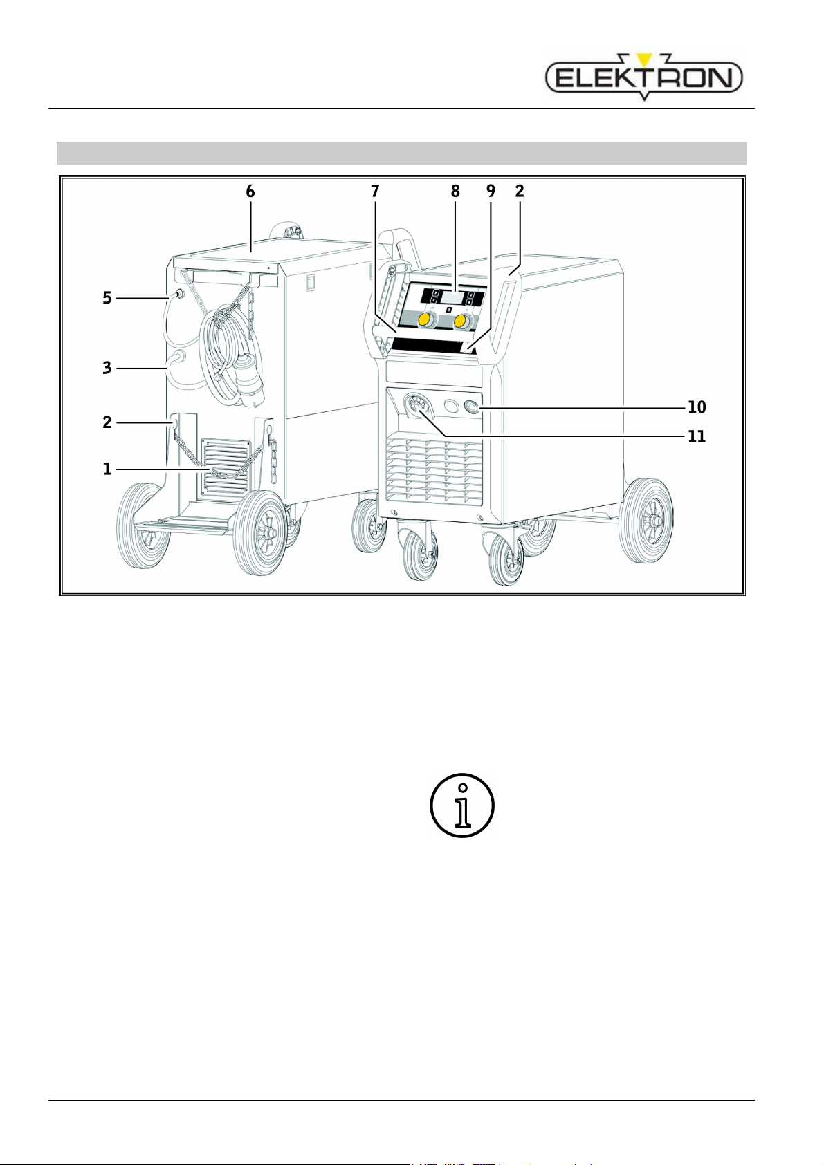
1 Machine elements
Fig. 1: Machine elements
1 Safety chain for gas
2 Hoisting points
3 Mains cable
5 Gas hose
6 Tray area
7 Handle
8 Control panel
9 Main switch
10 Socket for ground cable
11 Central socket
Some depicted or described acces-
of delivery.
Subject to change.
4
Page 5
MULTIMIG 200
garded, this can cause slight or
Disregarding danger warnings can
cause damage to work pieces,
Designates useful information
Read the user information in the
Pull out the mains plug before
chine is only possible if you read
fore using the machine for the first
Before starting any welding work,
clear away any solvents,
degreasing agents, and other
flammable materials from the
working area. Cover flammable
materials which can not be moved.
Only weld if the ambient air
centrations of
t, acid vapours, gases or
flammable substances. Special
care must be taken during repair
work on pipe systems and tanks
tained
Never touch live parts inside or
outside of the housing. Never
ding electrodes or live
welding current parts in a machine
Do not expose the machine to
rain, do not spray water on it or
Always use a welding shield. Warn
other persons in the welding area
2 Explanation of symbols
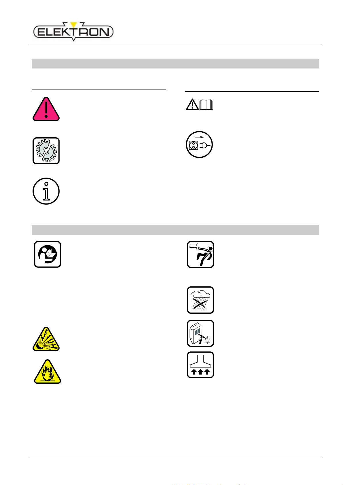
2.1 Meaning of the symbols in the
operation manual
Danger to life and limb!
If the danger warnings are disre-
severe injuries or even death.
Danger of property damage!
tools, and equipment.
General note!
about the product and equipment.
Explantion of symbols – Safety precautions
2.2 Meaning of the symbols on the
machine
Danger!
operation manual.
Disconnect the mains plug!
opening the housing.
3 Safety precautions
Hazard-free working with the ma-
the operating and safety instructions completely and strictly observe them.
Please obtain practical training be-
time. Follow the accident prevention regulations (UVV 1)).
contains no high con
dus
which contain or have con
flammable liquids or gases.
touch wel
that is on.
steam blast it.
about arc-rays.
Please use a suitable extraction
system for gases and cutting
fumes. Always wear breathing
apparatus whenever there is a
risk of inhaling welding or cutting
vapours.
5
Page 6
MULTIMIG 200
The machine must be transported
or set up only on firm, level
surfaces. The maximum
admissible angle of inclination for
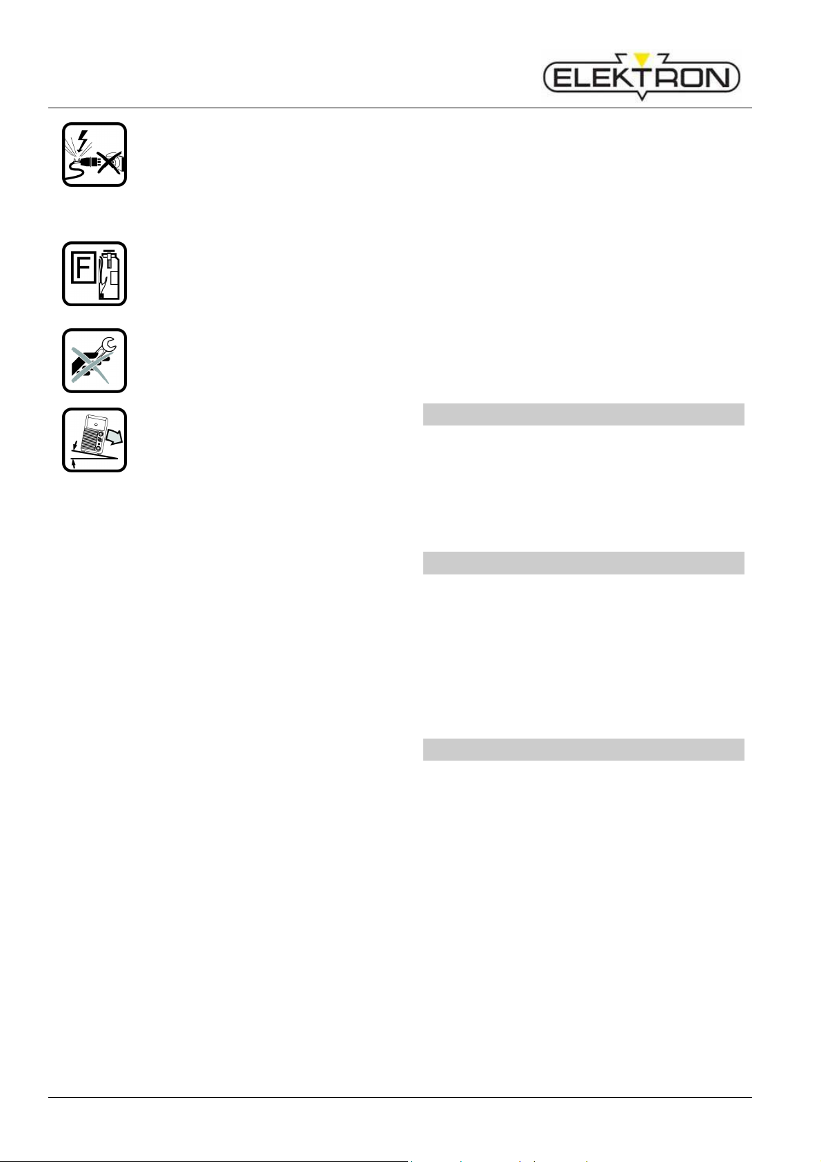
General regulation of use
If the mains cable is damaged or
severed in use, do not touch the
cable but unplug the mains plug
immediately. Never use a
machine if the mains cable is
damaged.
Keep a fire extinguisher near the
welding area.
Check the welding area for fire af-
ter welding (see UVV 1)).
Never try to disassemble the pressure reducer. Replace the defective one.
setting up or transporting is 10°.
Service and repair work may only be carried
out by a trained electrician.
Ensure that the ground cable has good and
direct contact near the welding location. Do
not allow welding current to pass through
chains, ball bearings, steel cables or
grounding equipment; this may melt them.
Secure yourself and the welding machine
when working in elevated or inclined areas.
The machine may only be connected to a
properly grounded mains supply. (Threephase four-wire system with grounded
neutral conductor or single phase-three-wire
system with grounded neutral conductor)
socket and extension cable must have a
functional protective conductor.
Wear correct protective clothing, leather
gloves and leather apron.
Protect the welding area with curtains or
mobile screens.
Do not use this machine to thaw frozen
water pipes or cables.
In closed containers, under cramped conditions, and in high electrical risk areas, only
use machines with the S sign.
Switch off the machine during breaks and
close the valve of the gas cylinder.
Secure the gas cylinder with a chain to
prevent it falling over.
Disconnect the mains plug from the mains
before changing the place of installation or
making repairs to the machine.
Please heed the safety regulations which apply
to your country.
Subject to change.
4 General regulation of use
This unit is for welding of steel, aluminium and
their alloys as well as for brazing with CuSi
wires for commercial as well as for industrial
use.
5 Unit protection
This machine is protected electronically
against overloading. Do not use fuses of higher
amperage than printed on the identification
plate.
Close the side cover before starting any
welding work.
6 Noise emission
The noise level of the unit is less than
70 dB(A), measured under standard load in accordance with EN 60974-1 in the maximum
working point.
6
Page 7
MULTIMIG 200
tion, storage and transport
may only be carries out within the
ranges indicated! Use outside of
this range is considered not used
with its intended purpose. The
Improper UVV inspections can
7 Ambient conditions
Temperature range of ambient air:
In operation:
-10 °C … +40 °C (+14 °F … +104 °F)
Transport and storage:
-25 °C … +55 °C (-13 °F … +131 °F)
Relative humidity:
up to 50 % at 40 °C (104 °F)
up to 90 % at 20 °C (68 °F)
-25 °C … +55 °C (-13 °F … +131 °F)
Opera
Electromagnetic compatibility (EMC)
9 Electromagnetic compatibility
(EMC)
This product is manufactured in conformance
with the current EMC standard. Please note
the following:
The machine is intended for welding in both
commercial and industrial applications
(CISPR 11 class A). Use in other
surroundings (for example in residential
areas) may disturb other electronic devices.
Electromagnetic problems during start-up
can arise in:
• Mains cables, control cables, signal and
telecommunication lines near the welding or
cutting area
• TVs / radios
manufacturer is not liable for damages cause by misuse.
Ambient air must be free of dust, acids, corrosive gases or other damaging substances!
8 UVV inspection
Operators of commercially-operated welding
systems are obliged to have safety inspections
of the equipment carried out regularly in
accordance with VDE 0544-4. ELEKTRON
recommends inspection intervals of 12 months.
A safety inspection must also be carried out
after alterations or repair of the system.
destroy the system.
• Computers and other control equipment
• Protection equipment such as alarm
systems
• Pacemakers and hearing aids
• Equipment for measurement and calibration
• Equipment with too little protection against
disturbances
If other equipment is disturbed it may be
necessary to provide additional shielding.
The affected area can be bigger than your
premises/property. This depends on the
building, etc.
Please use the machine in compliance with the
manufacturer's instructions. The machine
operator is responsible for installation and use
of the machine. Furthermore, the owner is
responsible for eliminating the disturbances
caused by electromagnetic fields.
7
Page 8
MULTIMIG 200
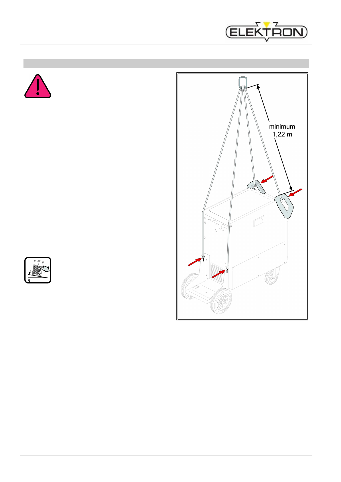
cal lifting equipment (e.g. crane,
etc.), only the hoisting points shown
here may be used. Use suitable
Each lifting point must be loaded
for example
put one load strap through both
handles, as this could lead them to
be pulled together and cause
lar
device to lift the machine by its
Remove the gas cylinder from the
The machine must be transported
faces. The maximum admissible
setting up or
Setup and transport
10 Set-up and transport
Danger of injury due to the device falling over and crashing!
When transporting using mechani-
load-carrying equipment.
separately. Do NOT,
breakage!
Do not use a fork-lift truck or simi
housing.
welding machine before transportation.
or set up only on firm, level sur-
angle of inclination for
transporting is 10°.
Fig. 2: Lifting point for 4-point hoisting
8
Page 9

MULTIMIG 200
A detailed description can be found
up“ Page
11 Brief operating instructions
in chapter. „Before start10 and chapter. „Start-up“ Page 14.
Place the inert gas cylinder on the unit and
secure it with the chain 1.
Remove the screw cap from the inert gas
cylinder and open the valve 32 briefly (blowout).
Connect the pressure reducer 13 to the inert
gas cylinder.
Connect the insert gas hose 5 from the unit
to the pressure reducer and open the
cylinder valve.
Insert the mains plug in the socket.
Connect welding return cable to connector
10 and the clamp to the workpiece.
Insert wire feed rollers 25 into wire feed unit
in accordance with the type of welding wire
selected, set contact pressure to 2.
Connect the torch to central connector 11
and insert the relevant contact tip to selected welding wire.
Insert welding wire.
Keep torch switch pressed and set main
switch 9 ON. Magnetic valve will be activated!
Adjust gas quantity at pressure reducer.
(Rule: wire diameter x 10 = gas quantity).
Hold down the wire feed switch 29 until the
welding wire projects from the torch neck to
the gas nozzle by approx. 20 mm.
Brief operating instructions
Mode key 47 for selection of 2-stroke mode.
Key characteristics 50 and operation knob
52 for adjusting the selected characteristic
line (material-gas-wire-combination).
Turn knob 45 to set material thickness of
the weldable material.
Torch switch pressed and held = welding.
Release the torch switch = welding process
completed.
9
Page 10
MULTIMIG 200
Before start-up
12 Before start-up
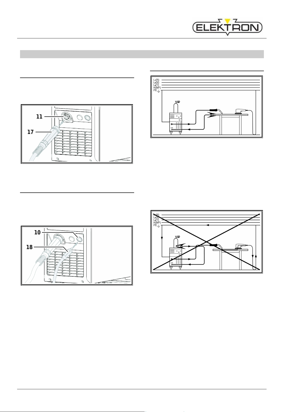
12.1 Connecting the torch
Connect the central connector 17 of the
torch to the central socket 11.
Fig. 3: Connecting the torch
12.2 Connecting the ground cable
Connect welding return cable 18 to con-
nector 10 and secure it by turning it clockwise.
12.3 Fastening the ground clamp
Fig. 5: Correct
Attach the ground clamp immediately be-
side the welding point so that the welding
current will not try to find its own return path
through machine parts, ball bearings or
electric circuits.
Connect the ground clamp firmly to the
welding bench or the workpiece.
Fig. 4: Connecting the ground cable
10
Fig. 6: Incorrect
Do not place the ground clamp on the
welding machine or the gas cylinder; otherwise the welding current will be carried via
the protective conductors and it will destroy
these.
Page 11

MULTIMIG 200
A protruding piece of wire out of the
pool can cause short circuits
to the side panel or bottom of the
When inserting the welding wire
spool, please pay attention to the
correct winding and make sure that
there are no protruding pieces of
Set the wire brake in such a way
tinue
running when releasing the torch
12.4 Insert the welding wire spool
Danger to life and limb and fire
hazard due to glowing welding
wire or parts!
wire s
unit.
wire.
that the wire spool doesn’t con
key.
Open side panel and turn the retaining nut
20 off from the wire spool holder 22.
Place the welding wire reel on the decoiler
mandrel and ensure that the carrier mandrel
23 locks in position.
For small welding wire reels, use an adaptor
(order number: 420 922).
Set the wire brake 21 so that, when the
torch switch is released, the welding wire
spool just does not run on.
Before start-up
Unscrew the contact tip of the torch.
Open side panel.
The diameter of the wire electrode must
agree with the legible embossed figure on
the wire feed rollers 25.
Swing the tilt levers 27 to the side and
thread the wire electrode through the inlet
nozzle 26 and central socket 11.
Fig. 8: open 4-roll wire feed
Swing the lever back 28 and secure in po-
sition with the tilt levers 27.
Fig. 7: Decoiler mandrel
12.5 Thread the wire electrode in
Fig. 9: close 4-roll feed
Turn on the machine at mains switch 9.
11
Page 12

MULTIMIG 200
Before start-up
Fig. 10: Wire feed button
Press wire feed button 29.
Adjust the contact pressure using the reg-
ulation screws 27 so that wire feed rollers
25 just slip when the welding wire spool is
stopped. The wire must not be jammed or
deformed.
A B C
Correct
Fig. 11: Wire feed rollers
Contact pressure
too high
Note for wire feed unit with 4 rollers:
Adjust the contact pressure of the wire feed
rollers 25 on the side of the inlet nozzle 26
to be less than on the side of the central
socket 11 in order to keep the wire
electrode under tension in the wire feed
unit.
Push the wire feed button 29 until the wire
protrudes from the torch neck by about
20 mm.
Screw the contact tip matching the wire
thickness into the torch and cut off the
protruding end of the wire.
12.6 Connecting the inert gas cylinder
Wrong wire feed
roller
Set the insert gas cylinder 14 down on the
carrier plate and secure it with the chain 1.
Briefly open the gas cylinder valve 32
several times in order to blow out any dirt
particles present.
Connect the pressure reducer 13 to the inert
gas cylinder 14.
Screw the inert gas hose 5 to the pressure
reducer.
Open valve 32 of shielding gas bottle 14.
Turn the machine off at main switch 9.
Press torch key and keep it pressed.
Turn on the machine at mains switch 9.
Solenoid valve will be switched on for 10
seconds.
Set the gas quantity using adjusting screw
35 of the pressure reducer 13. The gas
quantity will be displayed on the flowmeter
34.
Rule of thumb:
Gas volume = wire diameter x 10 l/min.
The cylinder content is indicated on the
content manometer 33.
Fig. 12: Connecting the inert gas cylinder
12.7 Changing the wire electrode
12
Page 13

MULTIMIG 200
ment parts depend upon the type of
torch used and the diameter of the
the
Change the wire feed rollers. Select the
most suitable rollers for the application.
Fig. 13: Wire feed rollers
A Steel feed roller
B Aluminium feed roller
C Knurled feed roller (for flux-cored wire)
Before start-up
Shorten the protruding plastic core so that it
is tight up against the wire feed roller, and
slide the appropriately shortened support
tube over the protruding plastic core for
stabilisation.
All:
Tighten the torch and thread the wire elec-
trode in.
The order numbers of the replace-
wire, and can be obtained from
torch spares lists.
Fig. 14: Marking of wire feed rollers
Replace the steel torch with an appropriate
torch, or change the wire feed spiral.
Wire feed spiral: (for steel or flux-cored
wire)
Remove the existing wire feed spiral or
plastic core and insert the new wire feed
spiral. (Refer to the operating manual for the
torch)
Insert the guide tube 85 into the central
connection.
Plastic core: (for aluminium, stainless steel
or CuSi wire)
Remove the existing wire feed spiral or
plastic core and insert the new plastic core.
(Refer to the operating manual for the torch)
Remove the guide tube 85 from the central
connection.
Fig. 15: Wire feed
7 Central socket
17 Central connection (torch)
25 Wire feed roller
38 Retaining nipple (=clamp) of the plastic
liner for 4.0 mm and 4.7 mm outside
diameter
39 O-ring
40 Union nut
41 Plastic liner
42 Support tube for plastic cores with 4 mm
OD Support tube not required with OD of
4.7 mm.
43 Guide tube
44 Wire feed spiral
13
Page 14

MULTIMIG 200
Start-up
13 Start-up
13.1 Control console MULTIMIG 200
Fig. 16: Control console MULTIMIG 200
Fig. 17: Graphic display
14
Page 15

MULTIMIG 200
9 Main switch for turning the welding
machine ON and OFF.
45 Turning knob for setting material
thickness/welding voltage/welding step.
46 Key button secondary parameter to
access the secondary parameter menu.
When within this menu this key serves to
end it.
47 Trigger Mode to select 2-stroke, 4-stroke,
spot welding or interval mode.
48 Key button menu to access the main
menu. Pressing this key will move one
level back.
49 Graphic display displays all information in
clear text.
50 Key Tiptronic/characteristics direct access
to the Tiptronic menu alt. characteristics
menu (if Tiptronic is switched off).
51 Key Secondary parameter access the
secondary parameter directly. Within the
menu press this key to end menu.
52 Operation knob Menu Turning knob wire
feed serves to:
• select menu (turn)
• confirm menu option (press)
• setting wire feed
• setting secondary parameter
55 Display mode displays the selected mode
by symbol.
56 Display characteristics displays the set
characteristic line.
57 Display Tiptronic-Job if the job no. is
followed by an asterisk (*) on the display,
a min. parameter of a saved job has been
changed.
58 Display wire feed correction displays the
wire feed as correction value differing from
the characteristic line in %.
59 Display wire feed displays the actual wire
feed speed in m/min.
Start-up
60 Display welding step displays the selected
welding step.
61 Display material thickness displays the
selected material thickness of the
workpiece in mm.
62 Display welding voltage displays the
selected welding voltage in Volt.
13.2 Start-up
Select with mode key 47 the 2-stroke mode.
Press key characteristics 50 to enter menu
characteristics.
Set matching characteristic line (material-
gas-wire combination) by turning operation
knob 52.
Confirm the characteristic line by pressing
operation knob 52.
Press operation knob 52 again to end menu
and return to standard display.
Set the required material thickness alt.
welding step by using turning knob 45.
The machine is ready for welding.
Use operation knob 52 to correct the wire
feed if needed.
15
Page 16

MULTIMIG 200
Start-up
13.3 Current / voltage display
The actual values of welding voltage and
welding current are displayed during and after
welding (hold function).
These values can be displayed individually or
together on the graphic display.
Possible display:
Welding voltage and welding current
Welding voltage
Welding current
Fig. 18: Display mode
Change of display modern
Fig. 19: Torch PowerMaster
65
Torch display displays the actual welding
step or wire feed speed in Tiptronic mode.
The current job will be displayed.
66 Torch rocker switch Change welding step
and wire feed speed. Between active jobs
can switched over whilst being in Tiptronic
mode.
67 Torch key „Mode“ By pressing (for at least
2 seconds) changeover between Tiptronic
and regular mode will take place. A quick
press in regular mode change between
wire feed, welding step and material
thickness (at selected characteristics).
Press menu key 48.
Select menu option „Display mode“ by
pressing operation knob 52.
Confirm menu option „Display mode“ by
pressing operation knob 52.
Set the desired display mode by turning
operation knob 52.
Confirm the desired display by pressing
operation knob 52.
For about 2 seconds a preview of the dis-
play will be shown if the display mode has
been changed.
13.5 Deactivate operation mode
The operation mode spot welding and interval
can be deactivated in the menu and will no
longer be accessable with mode key 47.
Press key menu 48.
Set menu to „options“ by turning operation
knob 52.
Confirm menu „options“ by pressing op-
eration knob 52.
Set the menu option „interval welding“ or
„spot welding“ by turning operation knob 52
for deactivation.
Confirm the menu option by pressing opera-
tion knob 52.
Select and confirm the menu option „off“ by
using operation knob 52.
13.4 Torch with remote control
16
Page 17

MULTIMIG 200
Fig. 20: Interval-welding deactivated
Press key 46, 50 or 51 to end menu and
return to standard display.
13.6 Characteristic line
Select characteristic line
Press key menu 48.
Set menu option „characteristic line“ by
turning operation knob 52.
Confirm menu option „characteristic line“ by
pressing operation knob 52.
Set required characteristic line by turning
operation knob 52.
Confirm characteristic line by pressing op-
eration knob 52.
Start-up
Fig. 22: „noP“ (no program)
Select a suitable welding step with turning
knob 45.
13.7 Mode Manual
Manual welding mode allows welding independent of characteristic lines.
Press key menu 48.
Select menu option „characteristics“ by
turning operation knob 52.
Confirm menu option „characteristics“ by
pressing operation knob 52.
Select menu option „manual“ by turning
operation knob 52.
Confirm menu option „manual“ by pressing
operation knob 52.
Press key 46, 50 or 51 to exit menu and
return to standard display.
Fig. 21: Characteristics
Press key 46, 50 or 51 to exit menu and
return to standard display.
If the graphic display shows „noP“ (no pro-
gram) for material thickness, the set welding
step is inapplicable for the selected
characteristic line.
Fig. 23: Manual mode
13.8 Secondary parameters
17
Page 18

MULTIMIG 200
Start-up
Press key secondary parameter 46 or 51 to
open the secondary parameter menu.
Select the required secondary parameter by
turning operation knob 52.
Confirm set secondary parameter by
pressing operation knob 52.
Set parameter value 72 as required by
turning operation knob 52.
Activate Tiptronic
Press key menu 48.
Select menu option „Tiptronic“ by turning
operation knob 52.
Confirm menu option „Tiptronic“ by pressing
operation knob 52.
Set menu option „Tiptronic on/off“ by turning
operation knob 52.
Confirm menu option „Tiptronic on/off“ by
pressing operation 52.
Set and confirm option „on“ with operation
knob 52.
Fig. 24: Secondary parameters
70 Symbol secondary parameter
71 Factory setting
72 Parameter value
Confirm parameter value 72 by pressing
operation knob 52.
Press key 46, 50 or 51 to exit menu and
return to standard display.
13.9 Tiptronic
The Tiptronic function provides 10 separate
jobs. All settings and adjustments made on the
control panel are stored in each job.
The Tiptronic function also gives the user
certain advantages, e.g. frequently recurring
welding jobs can be assigned to specific job
numbers, or different welders can save their
individual settings in „their“ job.
Factory setting for Tiptronic function is deactivated.
Fig. 25: activate Tiptronic
Press key 46, 50 or 51 to exit menu and
return to standard display.
Save job
Press key Tiptronic 50.
Set menu option „Job save“ by turning op-
eration knob 52.
Confirm menu option „Job save“ by pressing
operation knob 52.
Select the required saving position
(J00 … J09) by turning operation knob 52.
Confirm the job by pressing operation knob
52.
If the job to be saved is already existent / allocated; a safety question before overwriting
appears.
18
Page 19

MULTIMIG 200
Fig. 26: safety question
Select „YES“ for overwriting the job by
turning operation knob 52.
Confirm „YES“ by pressing operation knob
52.
Fig. 27: Save job
If required the job name can be changed.
(see „edit job ext).
Save the job by pressing key 51.
Press key 46, 50 or 51 to exit menu and
return to standard display.
Edit Job-text
Press key Tiptronic 50.
Set menu option „edit job text“ by turning
operation knob 52.
Confirm menu option „edit job text“ by
pressing operation knob 52.
Select the job no. where text must be edited
by turning operation knob 52.
Confirm the job no. by pressing operation
knob 52.
Start-up
Fig. 28: edit job text
Press key mode 47 to edit numbers.
Press key secondary parameter 46 to edit
letters.
Repress key secondary parameter to
change between capital and small letters.
Set the required number or letter by turning
operation knob 52.
Confirm number or letter by pressing op-
eration knob 52.
Repeat above procedure for each character.
Use key Tiptronic 50 to go back stepwise in
order to correct a character.
Press key secondary parameter 51 to fi-
nalize the saving process.
Press key 46, 50 or 51 to exit menu and
return to standard display.
Select job
Press key Tiptronic 50.
Set menu option „select job“ by turning
operation knob 52.
Confirm menu option „select job“ by press-
ing operation knob 52.
A listing of all existing jobs will be displayed
in the menu. The currently selected job is
marked with a tick (√) on the right side.
19
Page 20

MULTIMIG 200
Start-up
Fig. 29: select job
Set the required job by turning operation
knob 52.
Confirm the job by pressing operation knob
52.
Active job summary
Tiptronic-Jobs can be set either active or inactive.
When PowerMaster torch is connected and
Tiptronic function is active, use rocker switch to
switch between active jobs.
Press key Tiptronic 50.
Select menu option „Active Jobs“ by turning
operation knob 52.
Confirm menu option „Active Jobs“ by
pressing operation knob 52.
A listing of all existing jobs will be displayed
in the menu. All active jobs are marked with
a tick (√) on the right side.
Press key 46, 50 or 51 to exit menu and
return to standard display.
Copying a job
Press key Tiptronic 50.
Select menu option „copy job“ by turning
operation knob 52.
Confirm menu option „copy job“ by pressing
operation knob 52.
Select the job to be copied by turning op-
eration knob 52.
Fig. 31: Copy job: source
Confirm the job by pressing operation knob
52.
Select the job to be overwritten by turning
operation knob 52.
Fig. 30: Active job summary
Select the job to be activated or deactivated
by using operation knob turning knob 52.
Activate or deactivate the job by pressing
operation knob 52.
20
Fig. 32: Copy job: target
Confirm the job by pressing operation knob
52.
Safety question „copy job?“ appears.
Select „YES“ to copy by turning operation
knob.
Page 21

MULTIMIG 200
Fig. 33: Copy job: safety question
Confirm „YES“ by pressing operation knob
52.
Press key 46, 50 or 51 to exit menu and
return to standard display.
Delete job
Press key Tiptronic 50.
Select menu option „delete job“ by turning
operation knob 52.
Confirm menu option „delete job“ by press-
ing operation knob 52.
Select the job to be deleted by turning op-
eration knob 52.
Confirm this job by pressing operation knob
52.
Safety question „delete job?“ appears.
Select „YES“ to delete this job by turning
operation knob 52.
Start-up
13.10 Special functions
Gas test
Turn the unit OFF using main switch 9.
Press the torch key and keep it pressed.
Turn the unit ON using main switch 9.
The solenoid valve of the unit will go on and
the gas supply can be tested / adjusted. The
function is active for 30 seconds and will be
automatically stopped. Re-pressing the
torch key can interrupt the gas test.
Fan test
Turn the unit ON using main switch 9.
The fan will start for function purposes.
Operation panel test
Press the mode key 47 for at least 2 sec-
onds.
The complete display panel of the graphic
display will flash.
Press the key operation mode 47 again.
Another display test follows.
Press the key operation mode 47 again.
The operation panel test will be initiated.
Press and turn the keys as shown in the
graphic display.
If there is no input for 20 seconds, the operation panel test will be cancelled automatically.
13.11 Reset setting
Factory settings
Press key menu 48.
Select menu option „options“ by turning
Fig. 34: Delete job
Confirm „YES“ by pressing operation knob
52.
Press key 46, 50 or 51 to exit menu and
return to standard display.
operation knob 52.
Confirm menu option „options“ by pressing
operation knob 52.
Select menu option „Factory settings“ by
turning operation knob 52.
Confirm menu option „Factory Settings“ by
pressing operation knob 52.
Safety question „ ...reset?“ appears.
21
Page 22

MULTIMIG 200
All welding and secondary
ry
Start-up
Attention! All personal settings
will be lost.
parameters are reset to their facto
set-tings.
Fig. 35: Factory settings
Select „YES“ by turning operation knob 52
to reset all values to factory settings.
Confirm „YES“ by pressing operation knob
52.
Safety question „delete all jobs?“ appears.
Attention! All Tiptronic-jobs will
be deleted.
Fig. 36: Delete all jobs
Select „YES“ by turning operation knob 52
to delete all jobs.
Confirm „YES“ by pressing operation knob
52.
22
Page 23

MULTIMIG 200
14 Menu structure
Menu structure
23
Page 24

MULTIMIG 200
Menu structure
Main menu Level 1 Level 2 Note
Sprache /
Language
Characteristics
Display Mode
Tiptronic
Options
Deutsch
English
Select menu language
…
Manual
SG 2/3 0,8 mm 82/18
All settings can be performed independently
from a characteristic line.
Depending on type of model are various
characteristics set in the menu
…
(material-gas-wire combination)
Current and Voltage
Welding voltage
Different display settings can be selected
Welding current
see chapter „Tiptronic“ page 18
EU
Characteristic type
AWS
Display in accordance to EU (European)
classification
Display in accordance to AWS
(American Welding Society) classification.
Interval-Welding On Off To switch interval welding on/off
Spot Welding On Off To switch spot welding on/off
Diagnosis
… reset
Factory Settings
No Yes
Delete all jobs?
No Yes
Firmware Version Displays Firmware Version
Master reset to reset all settings back to factory
settings
To delete all jobs
Serial Number Displays serial no
Configuration Displays machine configuration
Operating Hour
Counter
Displays welding time in hours and minutes
Op. voltages 60/24V Displays voltages in Volt
Transf. Temperature Displays temperature in °C
Main menu Level 1 Factory settings Range
Parameters
Spot welding time 1,0 s 0,1…10,0 s
Interval time-Welding 1,0 s 0,1…10,0 s
Interval time-Wait 0,2 s 0,1…1,0 s
Note
Only available in spot
welding mode
Only available in interval
mode
Gas pre-flow 0,1 s 0,0…10,0 s
Wire creep speed 2,0 m/min 1,0…15,0 m/min
Wire burn back time 100 % 0…300 %
Gas post-flow 0,5 s 0,1…20,0 s
24
Page 25

MULTIMIG 200
As long as there is an error code on
15 Messages
In case of failure, a failure code is displayed in
graphical display 49.
Code
noP no program
E01 Excessive temperature The equipment has been overheated
E02 Mains overvoltage Mains input voltage too high Check mains voltage
Error description Note Rectification
Instead of material thickness „noP“ is
displayed. Welding is not possible at
activated characteristic line and set
welding step
display welding is not possible.
Select a different welding step
Allow the system to cool down in
standby, check the ventilation system
Messages
E03 Overcurrent
E06 Overvoltage Output voltage too high Inform Service
E07
E08 Wire feed
E09 Voltage-measuring Voltage measuring system defective Inform Service
E10 Torch connector/- cable
E13 Temp. sensor error
E14 Supply voltage
E15 Power measuring Fault at power measuring Inform Service
E16
EEProm checksum
error
Supply voltage motor
and main contactor
Output current is too high / Permanent short circuit
Setting data faulty or missing Switch the equipment off and on again
Too high power intake from wire
feed motor (Motor Over-Current)
Welding potential on torch control
cable
Thermal sensor not ready for operation
internal supply voltage too low
(18V~ / 24V-)
Internal supply voltage is too little
(42V~ / 60V-) /
PE conductor monitoring input
(Fault current to protective earth
conductor)
Inform Service
Blow down torch package with
pressured air and check pressure on
wire feed rolls
Check torch / exchange
Inform Service
Check mains voltages
Check power supply voltage / Check
connection of the workpiece cable and
ground clip, check for short-circuits
between welding wire and housing
E17
E18 Error configuration
Tab. 1: Massages
Peripheral devices
overload/ short circuit
Short circuit in torch or hose package, gas valve or feed line, wire run
key or line
Faulty or wrong pc-board, wrong
software system played
Test alt. exchange the connected torch
Inform Service
25
Page 26

MULTIMIG 200
Troubleshooting
16 Troubleshooting
Fault Possible cause Rectification
Torch becomes too hot Contact tip not tightened properly check
Torch switch has no function
when actuated
Open circuit in control cable in the torch
Thermal protection has triggered Allow the equipment to cool
Wire sticking or burnt onto
contact tip
Burr at start of wire Trim the end of the wire
Wire feed irregular or failed
completely
Torch faulty Check and replace if necessary
Union nut from torch hose pack to central
Tighten the union nut
socket is not correctly tightened
Check and replace if necessary
hose pack
down at no-load
Wire electrode jammed on the reel Check and replace if necessary
Incorrect contact pressure on wire feed unit Set as described in the operat-
ing instructions
Guide tube in the central socket is missing
Insert the guide tube or clean it
or dirty
Welding wire reel badly wound Check and replace if necessary
Surface rust on wire electrode Check and replace if necessary
Torch internal coil clogged with abrasion
dust
Unscrew the torch from the
equipment, remove contact tip
from torch and blow out the coil
with compressed air
Torch internal coil flexed Check and replace if necessary
Wire brake setting too hard Set as described in the operat-
ing instructions
Equipment switches off Duty cycle exceeded Allow the equipment to cool
down at no-load
Insufficient cooling of components Check air inlet and outlet on the
equipment
Arc or short circuit between
contact tip and gas nozzle
Unstable arc Contact tip does not match the wire diameter
A spatter bridge has formed between the
contact tip and the gas nozzle
Remove using suitable special
pliers
Check and replace if necessary
or contact tip is worn
Control panel is completely
dark
Phase missing Check the equipment at a dif-
ferent power socket. Check the
supply cable and mains fuse
Inert gas missing Gas cylinder empty Replace
Torch faulty Check and replace if necessary
Pressure reducer dirty or faulty Check and replace if necessary
Gas cylinder valve faulty Replace gas cylinder
26
Page 27

MULTIMIG 200
Troubleshooting
Fault Possible cause Rectification
Inert gas does not switch off Gas valve dirty or sticking Remove torch and pressure
reducer, blow out the gas valve
in the opposite flow direction
with compressed air
Inert gas feed insufficient Inert gas quantity set incorrectly at the
pressure reducer
Pressure reducer dirty Check the pressure reducing
Torch or gas hose blocked or leaking Check and replace if necessary
Inert gas blown away by draughts Eliminate the draughts
Welding power is reduced Phase missing Check the equipment using a
Set the inert gas quantity as
described in the operating
instructions
nozzle
different power socket; check
the supply cable and the mains
fuses
Insufficient ground contact at workpiece Create a good clear ground
connection
Ground cable not correctly inserted at the
equipment
Lock the ground connector at
the equipment by turning clockwise
Torch faulty Repair or replacement
Ground cable connector
becomes hot
Wire feed unit has increased
wire abrasion
The connector was not locked by turning
clockwise
The wire feed rollers do not match the wire
diameter
Check
Fit the correct feed rollers
Incorrect contact pressure on wire feed unit Set as described in the operat-
ing instructions
Tab. 2: Troubleshooting
27
Page 28

MULTIMIG 200
In this case the manufacturer’s
r
Repair and maintenance
17 Repair and maintenance
Please heed the current safety
and accident prevention regulations during all maintenance
and repair work.
17.1 Check regularly
Check the following points for damage
before starting up the welding machine:
• Mains plug and cable
• Welding torch and connections
• Ground cable and connection
Blow out the welding machine every two
months.
Switch the machine off.
Disconnect the mains plug.
Unscrew both side panels of the unit.
Blow out the welding machine with dry, low
pressure compressed air. Avoid blowing
directly on the electronic components from a
short distance, to prevent damage.
Screw the two side panels onto the machine
back again.
Never make repairs or technical
changes yourself.
warranty is no longer valid.
If you experience problems o
need repairs, contact a dealer authorised by ELEKTRON.
17.2 Torch care
Remove the weld spatter from inside the
gas nozzle using suitable tongs.
Spray the inside surface of the gas nozzle
with a releasing agent, or use nozzle
protection paste.
This will prevent weld spatter from being
burnt on.
28
Page 29

MULTIMIG 200
18 Technical data
Technical Data
Welding range (I2
Welding range (U2
No-load voltage V
Voltage setting Steps
Slope characteristic constant voltage characteristic line
ED 100 % A
ED 60 % A
ED at max. current %
Usable wires steel Ø mm
Usable wires aluminium Ø mm
Usable wires CrNi Ø mm
Usable wires CuSi Ø mm
Wire feed rate m/min
Mains
Mains voltage 3~ (50/60 Hz) V
Positive mains voltage tolerance %
Negative mains voltage tolerance %
Input power S1 (100 %) kVA
Input power S1 (60 %) kVA
Input power S1 (max. Strom) kVA
Current input I1 (100 %) A
Current input I1 (60 %) A
Current input I1 (max. Strom) A
Maximum effective mains current (I1
Power factor (at I2
Mains fuse (slow-response) A
Mains plug
Machine
Protection class
(in accordance with EN 60529)
Insulation class
Cooling method
Noise emission dB(A)
Dimensions and weights
Dimensions mm 880 x 400 x 755
Weight kg
Standard equipment
Feed unit Rolls
Tab. 3: Technical Data
1
) measured at 40° C environmental temperature
2
) reduced performance at 1~ 230 V operation mode
1)
min
max
…I2
min
)
max
…U2
) V
max
)
eff
) cos ф
MULTIMIG 200
A
A
IP
15…200
14,8…24,0
14,4…32,5
21
100
130
20
0,6…1,0
1,0…1,2
0,8…1,0
0,8…1,0
0,5…25
3~ 400
15
25
2,7
4,0
7,3
3,9
5,4
10,6
4,7
0,89
16
CEE 16
23S
F
F
< 70
74
4
Technical data
29
Page 30

MULTIMIG 200
Options and accessories
19 Options and accessories
19.1 Torch holder
Fig. 37: Torch holder assembly left
Order number: 420 958
20 Disposal
Fig. 38: Torch holder assembly right
Order number: 420 959
Only for EU countries.
Do not dispose of electric tools together with household waste material!
In accordance with European Council Directive
2002/96/EC on electrical and electronic
equipment waste and its implementation in
accordance with national law, electric tools that
have reached the end of their service life must
be collected separately and returned to an
environmentally compatible recycling facility.
21 Service
ELEKTRON Bremen GmbH Hinterm Sielhof 22 D-28277 Bremen Germany
Phone.: +49 (0)421 54 90 6-906 Fax: +49 (0)421 54 90 6-19
Web: www.elektron-bremen.de Mail: service @ elektron-bremen.de
30
Page 31

MULTIMIG 200
22 Schematic
Schematic
31
Page 32

Bl it zR o t ar y G m b H
Phone +49 / (0)421 / 54 90 6-906 Fax +49 / (0)421 / 54 90 6-19 vertrieb@elektron-bremen.de www.elektron-bremen.de
B r a n c h B r e m en
H i n t e r m Si e l h o f 22
D - 28 2 7 7 Br em e n
 Loading...