

Page 1

Made in Germany
Operating Manual
HS 12/24-120
HS 12/24-120B
Charger for 12V und 24 V Lead- and Li-Ion Rechargeable Batteries
Charging Current up to 120 A
Article-No.: 328 xxx GB
Revision: 0.1 – Translation
Date: 01.08.2018
Be sure you have read and understood this operating
manual before starting any work!
Keep operating manual for later use!
Page 2

2
© BlitzRotary GmbH
Hüfinger Straße 55
D-78199 Bräunlingen
Germany
Phone: +49 (0)771.9233.0
Fax: +49 (0)771.9233.99
E-Mail: vertrieb@elektron-bremen.de
Internet: www.elektron-bremen.de
Issued by:
BlitzRotary GmbH, Bräunlingen
Page 3

HS 12/24-120
Table of Contents
3
Table of Contents
1 General Information 5
1.1 Information concerning this operating manual ............................................................................... 5
1.2 Copyright ........................................................................................................................................ 5
1.3 Symbols .......................................................................................................................................... 5
1.4 Disclaimer ....................................................................................................................................... 7
1.5 Warranty and guarantee ................................................................................................................ 7
1.6 Customer Service ........................................................................................................................... 7
1.7 Health and Safety ........................................................................................................................... 7
1.8 Intended Use .................................................................................................................................. 7
1.9 Responsibilities of the Operating Company ................................................................................... 8
1.9.1 General Obligations ........................................................................................................ 8
1.9.2 Demands on Employees ................................................................................................. 9
1.9.3 Personal protective equipment (PPE) ............................................................................ 9
1.10 Particular Dangers ....................................................................................................................... 10
1.10.1 Dangers due to the equipment ..................................................................................... 10
1.10.2 Dangers due to work environment ................................................................................ 11
1.10.3 Danger to this equipment and other property ............................................................... 11
1.11 Correct behaviour in accidents and dangerous situations ........................................................... 12
1.12 Safety devices .............................................................................................................................. 13
1.13 Safety labels and markings on the unit ........................................................................................ 13
1.13.1 On the top cover ........................................................................................................... 13
1.14 Spare parts ................................................................................................................................... 13
1.15 Waste management and environmental protection ..................................................................... 14
2 Transport, packing, storage 14
2.1 Safety during transport ................................................................................................................. 14
2.2 Unpacking .................................................................................................................................... 14
2.3 Acceptance after shipping ............................................................................................................ 15
2.4 In case of further transport / return of goods ................................................................................ 15
2.5 Storage ......................................................................................................................................... 15
3 Design and functionality 16
3.1 Short description .......................................................................................................................... 16
3.2 Overview front panel .................................................................................................................... 16
3.3 Rear stand .................................................................................................................................... 17
3.4 Connection cables ........................................................................................................................ 17
3.5 Description of the unit .................................................................................................................. 17
4 Operation 18
4.1 Provisions ..................................................................................................................................... 18
4.2 Connect the electrical system ...................................................................................................... 19
4.3 Switching on ................................................................................................................................. 19
4.3.1 Checks before switching on .......................................................................................... 19
4.4 Start-up ......................................................................................................................................... 19
4.5 Charging / Trickle charging / Buffer operation (Charge Mode) .................................................... 19
4.6 External power supply / EPS operation (Support Mode) ............................................................. 20
4.7 Operation ...................................................................................................................................... 21
4.8 Operating modes .......................................................................................................................... 21
4.8.1 Auto-start function ......................................................................................................... 21
Page 4

HS 12/24-120
Table of Contents
4.8.2 Charging 12V ................................................................................................................22
4.8.3 Selection of battery type / Adjustment of charging parameters ....................................22
4.8.3.1 Selection of battery type ................................................................................22
4.8.3.2 Adjusting charge parameters ........................................................................23
4.8.4 Support Mode (External power supply EPS) ................................................................24
4.8.5 Charging rate test, deep discharged batteries ..............................................................24
4.9 Service-Menu ...............................................................................................................................25
4.9.1 General functions ..........................................................................................................25
4.9.2 Charging parameters ....................................................................................................25
4.9.3 De-sulphating program .................................................................................................26
5 Troubleshooting 27
5.1 Health and safety during troubleshooting.....................................................................................27
5.2 Error messages and troubleshooting tables ................................................................................27
5.2.1 Fault indicator ...............................................................................................................27
5.2.2 LED – Display Table .....................................................................................................28
6 Maintenance 29
6.1 Maintenance schedule .................................................................................................................29
6.2 Maintenance jobs .........................................................................................................................29
6.2.1 Personnel ......................................................................................................................29
6.2.2 Cleaning ........................................................................................................................29
6.3 Measures after maintenance ........................................................................................................29
7 Specifications 30
8 Index 31
9 Appendix 32
9.1 Training report ..............................................................................................................................32
Page 5

HS 12/24-120
General Information
5
1 General Information
1.1 Information concerning this operating manual
This operating manual will enable you to work efficiently and safely with this equipment.
The manual is an essential part of this product and must be stored ready at hand not far from the
equipment, so that people can use it at any time without any problems. Operators must read and
understand the manual before they carry out any work. Compliance with any and all information
contained herein concerning health, safety and safe behaviour and procedures is a prerequisite for
safe work.
Additionally, shall apply any and all local accident prevention regulations, any and all general safety
regulations, that may apply to the scope of application of this equipment.
Pictures, drawings etc. contained in this operating manual are supposed to convey a general
understanding of facts. In details, they may deviate from the reality you encounter.
Besides this operating manual, there may be specific instructions for units, components etc. They shall
apply accordingly.
1.2 Copyright
This operating manual is protected by copyright. It may be used for internal purposes, exclusively.
The manual and / or its contents may not be relinquished to third parties and/or communicated,
processed, used and / or reproduced in any way or form whatsoever (not even in excerpts and / or for
internal purposes) without the prior written consent of the manufacturer.
Contravention shall entail compensation claims.
All other rights reserved.
1.3 Symbols
Safety information
This manual uses symbols to highlight important safety information. In addition, there is always a
signal word heading the information indicating the severity of the danger or hazard that may be
encountered.
Be sure to comply with any and all safety information. Proceed with care and circumspection. Prevent
accidents and damage to people and property.
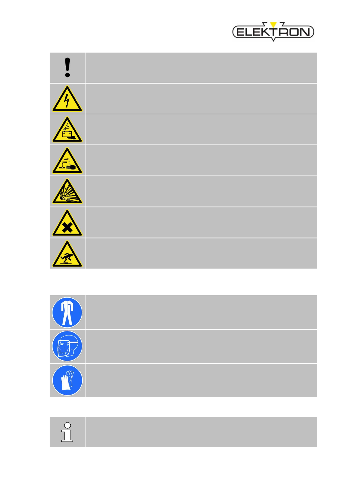
Warnings
DANGER!
… indicates a situation that is imminently dangerous and will entail the death of people
and severe injuries unless it is properly avoided and prevented.
WARNING!
... indicates a situation that may become dangerous and may entail the death of people
and severe injuries unless it is properly avoided and prevented.
CAUTION!
... indicates a situation that may become dangerous and may entail medium and small
injuries unless it is properly avoided and prevented.
Page 6
HS 12/24-120
General Information
CAUTION!
… indicates a situation that may become critical and may entail damage to property
unless properly avoided and prevented.
Electric Shock
Danger to life due to electricity
Warning about dangers due to batteries
Danger to persons and property due to incorrect handling.
Danger to life due to corrosive substances!
Battery acid is corrosive.
Danger to life due to explosive gases!
Danger of explosion due to oxyhydrogen during charging of batteries.
Avoid fire, open light and generating sparkles.
Harmful substances
Danger due to toxic, at least harmful vapors.
Stumbling hazards
Danger of injuries due to stumbling and falling.
Personal protective equipment (PPE)
Non-inflammable safety clothing
is a tight-fitting sort of special clothing that is not inflammable, covers arms and legs
completely and tears easily (instead of getting pulled in). Its main purpose is to protect
against burns.
Face screen
protects the face and eyes against splashes, flying sparks and other hot particles.
Safety gloves
protects the hands against splashes, flying sparks and other hot particles.
Never use wet gloves.
Tips and recommendations
NOTE!
... highlights information that may be helpful to maintain efficient and trouble-free
operation.
Page 7

HS 12/24-120
General Information
7
1.4 Disclaimer
Any and all information contained in this operating manual has been written on the basis of pertinent
standards and regulations, the state of the art, and the long-standing insights and experience of our
staff.
The manufacturer cannot be made liable for damage due to:
Non-compliance with this operating manual
Non-compliance with the purpose and intent of this equipment
Deployment of unskilled personnel
Unauthorised constructional changes, alterations etc.
Unauthorised changes, modifications etc. to design and engineering etc.
Use of unauthorised spare and wear parts
The scope of the delivery you actually receive may deviate from explanations and/or representations
in this manual - if and when you ordered special options, your equipment is a special design and/or
technical progress facilitates improvements.
Shall apply: any and all obligations and stipulations of the Delivery Contract, the General Terms of
Business and Terms of Supply and Delivery of the manufacturer as well as any and all legal
stipulations and regulations in force on the day the Contract was concluded.
We constantly strive to further develop and improve our products and their functionality. We, therefore,
reserve the right to implement technical changes without notice.
1.5 Warranty and guarantee
The guarantee conditions shall be as stipulated in the General Terms of Business of the manufacturer.
1.6 Customer Service
Our customer service will be happy to provide technical support. For contact information, see
page 2 of this manual. Please note: Our staff is always eager to learn about new information, insights
and / or experience our customers may derive from the work with our products that may be helpful for
their future improvement.
1.7 Health and Safety
This section contains an overview of the most important health and safety at work aspects in order to
protect employees and to guarantee safe and trouble-free operation.
Non-compliance with any and all of the information, safe behaviour and procedures etc. contained
herein may entail severe health and safety risks.
1.8 Intended Use
This equipment has been designed and built for the following purpose(s), exclusively, and shall be
used accordingly:
Page 8

HS 12/24-120
General Information
The battery charger HS 12/24-120 is intended for charging of rechargeable 12 or 24 V-wet lead
batteries (Lead-Calcium and EFB as well), as well as maintenance-free AGM-, Gel-, Fleece- and Li-Ion
rechargeable batteries exclusively, and must be operated within the limits of the specification and
operational limits ( refer to chapter 7 “Specifications”). Non-rechargeable batteries or primary
batteries must not be connected!
This charger is intended for use in industrial environments and may cause radio interference in
residential areas.
"Intended use" and "intended purpose" shall include proper compliance with any and all information
contained in this operating manual. Any and all use diverting from and / or going beyond the limits as
set by the equipment's intended purpose and use shall be deemed as misuse and may entail
dangerous situations.
WARNING! Misuse may entail danger
Misuse of this equipment may entail dangerous situations.
Therefore:
Do not operate this equipment unless clearly within its specs and limits of use
( see chapter 7 “Specifications”).
Do not use this equipment in explosive atmospheres.
Do not open, alter, modify and/or manipulate etc. this equipment.
The manufacturer shall not be held liable for any and all damage due to misuse of this equipment.
1.9 Responsibilities of the Operating Company
1.9.1 General Obligations
This equipment has been designed for professional use. The owner/operator or operating company
therefore being a businessman or commercial company, they are subject to any and all legal
obligations concerning health and safety at work. This means, in addition to this operating manual, any
and all accident prevention, health and safety at work and environmental regulations pertaining to this
equipment's scope of application shall apply as well.
This means in particular:
The operating company must be informed about any and all pertinent health and safety at
work regulations and must carry out a risk assessment in order to determine additional
hazards existing under the specific conditions in the specific work environment at the place of
operation. Any and all findings from such a risk assessment must then be used to draw up
additional operating instructions for the operation of this equipment.
During the entire lifetime of this equipment, the operating company must check in regular
intervals whether such additional operating instructions are still up to date and must update
them when necessary.
The operating company must unambiguously determine and communicate responsibilities
concerning the installation, operation, maintenance and cleaning of this equipment.
The operating company must make sure that any person handling this equipment has read
and understood this operating manual. Operating personnel, in addition, must be trained in
regular intervals and must be informed about the dangers existing in connection with this
equipment. (For a draft of a training report form, see "Appendix”
Page 9

HS 12/24-120
General Information
9
The operating company must equip operating personnel with suitable personal protective
equipment (PPE) and check it for proper working condition in regular intervals. Defective PPE
must be replaced with new ones.
The operating company must take appropriate and suitable fire protection measures and make
available fire extinguishers and first aid kits.
The operating company is responsible that the equipment is in proper working order at all times.
Therefore:
The operating company must make sure that any and all maintenance jobs described in this
manual are really carried out.
The operating company must have any and all safety labels, markings etc. on the equipment
checked for integrity and readability in regular intervals.
1.9.2 Demands on Employees
WARNING! People with insufficient skills may suffer injuries.
Inexpert handling may entail severe damage to persons and property.
Therefore:
Make sure that any and all activities are carried out by skilled personnel, only.
This equipment may be operated only by persons who do reliably their work properly.
Persons whose capability of reaction is impaired, e.g. by drugs, alcohol or medication, must
not be allowed to handle this equipment.
When selecting suitable operating personnel, be sure to respect occupational regulations and
legislation concerning skills, age etc.
This operating manual specifically names the following types of personnel who must have the
following skills:
Operator
The operator has been coached / trained by employees of ELEKTRON and / or an authorised
representative / dealer of ELEKTRON concerning his tasks and duties and possible hazards in
connection with inappropriate behaviour and confirms this with his signature (see draft of
training report form, "Appendix").
Service Personnel
refers to manufacturer's own service personnel and/or that of his representative / dealer. Such
service personnel have the professional training, skills and experience as well as knowledge of
pertinent regulations to carry out the jobs they accept and to identify, avoid and prevent
hazards on their own and without additional support.
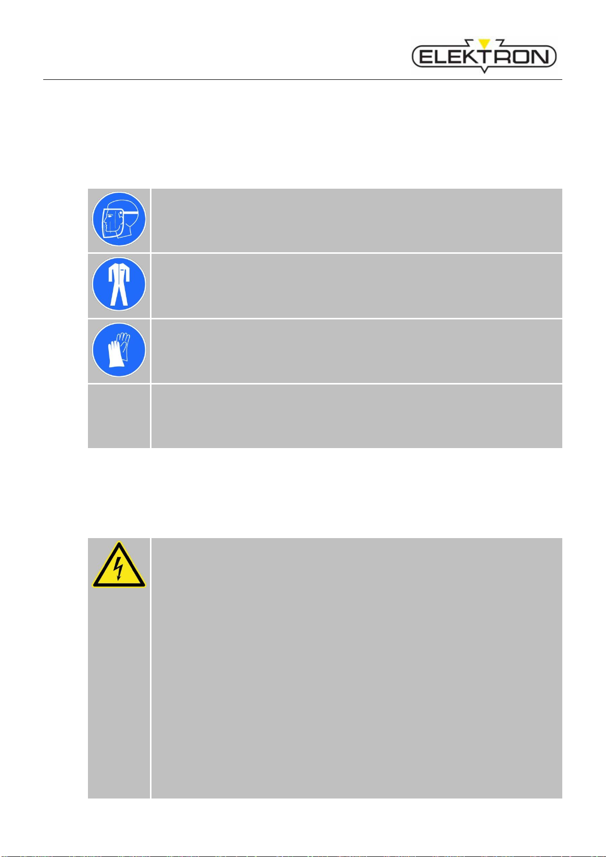
1.9.3 Personal protective equipment (PPE)
CAUTION! Insufficient protection against injuries
Defective safety clothing may not constitute a proper protection against injuries.
Therefore:
Be sure to check PPE for integrity and good working condition before you start any
works.
Replace defective PPE.
Consider manufacturer's instructions and expiration dates, when and where
applicable.
Page 10
HS 12/24-120
General Information
Wearing PPE during work is essential to minimise health and safety risks.
Be sure to be always wearing the appropriate PPE for the job at hand.
Be sure to take note of and comply with warning signs concerning PPE that may be installed at
the workplace.
Face screen
protects the face and eyes against splashes, flying sparks and other hot particles.
Non-inflammable safety clothing
is a tight-fitting sort of special clothing that is not inflammable, covers arms and legs
completely and tears easily (instead of getting pulled in). Its main purpose is to protect
against burns.
Safety gloves
protects the hands against splashes, flying sparks and other hot particles.
Never use wet gloves.
Furthermore
Do not wear long hair, rings, necklaces, watches or other jewellery.
Do not carry inflammable items such as matches or lighters.
1.10 Particular Dangers
1.10.1 Dangers due to the equipment Electricity
DANGER! Electricity constitutes a danger to life and limb.
Touching live components can result in a fatal electrical shock.
Therefore:
As soon as you notice any damage to insulation, disconnect the power supply and
have the damage repaired.
Do not open this equipment yourself. Have all repairs carried out by service
personnel, exclusively. Have works on electrical equipment carried out by skilled
electricians, exclusively.
Before any and all electrical works: disconnect power, earth and short. Check
whether equipment is really dead.
Keep live components away from liquids and humidity. They may cause short
circuits.
Protect cables against running over, contact with oils, aggressive substances, tools,
pointed and/or hot objects.
When pulling from a socket: Never pull on the cable. Pull on the plug.
Do not use the cable to trail or drag equipment over the floor. Always grab
equipment by the handles provided for that purpose.
Use strain relief clamps to protect cables.
Make sure protective ground conductors have been connected properly.
Page 11

HS 12/24-120
General Information
11
1.10.2 Dangers due to work environment Explosive Gases
DANGER! Explosive Gases constitute a danger to life and limb!
Charging batteries can produce explosive gases.
Explosion hazard due to oxyhydrogen gas formation.
Therefore:
Charge batteries in well ventilated rooms only.
Avoid fire, open light, and spark formation.
Corrosive substances
Danger! Danger to life due to corrosive substances!
Battery acid is corrosive.
Therefore:
Wear protective goggles.
If the acid is in contact with the skin or eyes, immediately rinse the affected area with
plenty of water. Then contact a doctor.
Stumbling hazards
WARNING! Possibility of injuries due to stumbling and falling.
The work environment may pose stumbling risks. Stumbling and falling may lead to
severe injuries.
Therefore:
Make sure the work area is tidy and free of clutter and offers enough freedom to
move.
Install cables and supply lines in such a way that they do not constitute a stumbling
trap.
Ensure a stable location of the charger.
1.10.3 Danger to this equipment and other property Batteries
WARNING! Material damage due to wrong supply voltage or charging not
suitable batteries!
When charging unsuitable batteries, property damage may occur.
Therefore:
Connect lead acid- or Li-Ion rechargeable batteries with 12 or 24 V rated voltage
with appropriate setting of the charger only!
Connect only rechargeable batteries.
Never charge frozen batteries.
Never charge damaged batteries.
Page 12

HS 12/24-120
General Information
Ambient conditions
WARNING! Material damage due to humidity, moisture and insufficient
ventilation
Under certain circumstances material damage may occur.
Therefore:
Protect the charger from moisture.
Set up the charger so that the air inlet and outlet is not blocked.
1.11 Correct behaviour in accidents and dangerous situations
Preventive measures
Be prepared to confront accidents and fires.
Be sure to have first aid equipment (kits, blankets etc.) and fire extinguishers ready at hand.
All personnel must know about accident signalling systems, first aid, rescue and escape
equipment.
Keep access ways for ambulances clear and open.
If there is a pungent smell of gas, there is an acute danger of explosion!
DANGER! Explosive Gases constitute a danger to life and limb!
Don’t switch off the charger!
Don’t disconnect the charging clamps!
Immediately ventilate the room very well!
After sufficient ventilation switch off charger.
Check battery!
Measures to be taken in case of accidents
Turn off power ( see chapter 1.12 “Safety devices”).
Initiate first aid.
Evacuate people from danger zone.
Alert persons in charge.
Alert fire brigade and ambulance service.
Keep access ways for ambulances clear and open.
Measures to be taken in case of work at the device
De-energise.
Secure against restarting.
Determine unit is de-energized.
Page 13

HS 12/24-120
General Information
13
1.12 Safety devices
WARNING! Danger to life due to insufficient protection against residual current!
Connection to mains socket: the device may only be connected to an electrical socket
equipped with an RCD switch (earth leakage circuit breaker) and an operational ground
system.
Fig. 1: On-/Off-Switch
On-/Off-Switch
By pressing the On-/Off-Switch (8) for about 3 - 4
seconds the unit will be switched into Stand-By Mode.
Disconnect the power plug to completely
disconnect the power supply!
1.13 Safety labels and markings on the unit
1.13.1 On the top cover
Observe operating instructions!
Open the device only by qualified
personnel!
Protect device against dripping
water!
Use only suitable tools!
1.14 Spare parts
WARNING! Wrong spare parts constitute a hazard.
Wrong and/or defective spare parts may constitute a safety hazard and may entail
errors, damage and even total destruction. Therefore:
Always use genuine spare parts made by the manufacturer.
Be sure to buy your spare and wear parts directly from the manufacturer or an authorised dealer. For
contact information , see page 2 of this manual.
8
Page 14

HS 12/24-120
Transport, packing, storage
1.15 Waste management and environmental protection
CAUTION! Inexpert handling may constitute an environmental hazard.
Inexpert handling of environmentally harmful substances, especially wrong disposal,
may constitute a hazard to the environment.
Therefore:
Be sure to take appropriate measures whenever harmful substances get (or threaten
to get) into the environment. In case of doubt, inform competent local authorities
about the hazard or damage.
Local authorities and specialised waste management companies will be happy to
advise you with your disposal issues.
Please also consider the following information.
Batteries and rechargeable batteries
Batteries contain toxic heavy metals. Batteries are subject to hazardous waste management and must
be collected by specialised companies or taken to special collection centres.
Electronic components
Electronic components and scrap are subject to hazardous waste management and must be collected
by authorised companies.
Other components
Unless you have concluded a return and / or disposal agreement with the manufacturer, please
disassemble and recycle components.
Scrap metals.
Recycle plastic parts.
Other components must be sorted by materials and disposed of accordingly.
2 Transport, packing, storage
2.1 Safety during transport
Inexpert transport
CAUTION! Improper transport may cause damage to property.
Improper transport may cause damage to property.
Therefore:
When you unload packing units and move them across your premises, proceed with
care. Consider symbols and information on packaging.
2.2 Unpacking
1. Do not remove packaging until immediately before installation.
During unpacking, do not use pointed tools.
2. Recycle packing materials.
Page 15

HS 12/24-120
Transport, packing, storage
15
What to do with packing materials
CAUTION! Improper waste disposal may cause environmental hazards.
Packing materials are valuable raw materials. In many cases, they can be recycled, i. e.
used again for packaging or in some other way or they can be further processed or
treated in some way.
Therefore:
Be sure to dispose of packing materials in sustainable manner and/or according to
local laws and regulations.
Observe local waste management legislation. In case of doubt, contact a specialised
company.
2.3 Acceptance after shipping
Check packing units immediately after delivery. Check for integrity, missing pieces and damage.
If you detect any external shipping damage, proceed as follows:
Do not accept delivery. Or accept under reserve.
Report damage on carrier's shipping papers or delivery ticket.
Initiate complaint procedure.
NOTE
Be sure to register a complaint as soon as a defect has been detected. Claims for
damages may be brought forward only within the deadlines set for complaints.
2.4 In case of further transport / return of goods
Use packing materials that correspond to original packing materials.
CAUTION! Improper transport conditions may cause damage to property.
Packaging with inappropriate dimensions, quality or weight, or cooling water left in
coolant tank may cause damage during transport.
Therefore:
Use packaging of appropriate size and quality.
2.5 Storage
Storage conditions:
Do not store packing units outdoors.
Provide for dry and dust-free storage.
Protect against aggressive media.
Protect against direct sun exposure.
Protect against mechanical shocks and vibrations.
Page 16

HS 12/24-120
Design and functionality
Storage temperature: –10 to 50 degrees centigrade.
–50 to 122 degrees Fahrenheit.
Rel. humidity: 85 % max.; no dew.
When storing equipment longer than three months, check general conditions of all parts and
packaging in regular intervals. If and when necessary, refresh or renew corrosion protection.
3 Design and functionality
3.1 Short description
The battery charger HS 12 / 24-120 is exclusively for charging 12 V and 24 V wet lead acid batteries
(also lead calcium, EFB), maintenance-free AGM, gel and fleece batteries as well as Li-ion
accumulators.
3.2 Overview front panel
Fig. 2: Overview front panel HS 12/24-120
2
3
4 5 6 7 8 1 9
10
Page 17

HS 12/24-120
Design and functionality
17
1 Touch display Graphical user interface
2 LED – yellow Charge Mode – Base charge
3 LED – yellow Charge Mode – Recharge
4 LED – green Charge Mode – End of charge, trickle charging
5 LED – blue Support Mode
6 LED – white / red Batterie missing / fault
7 USB-Interface Service, Program Update
8 Push button On/Off Put charger to pause or restart (press briefly)
Switch-off charger (press for about 3 seconds)
Switch-on charger (press briefly)
9 Mains connection worldwide standardized IEC connection socket
10 Connection for charging cables (+) red clamp, (–) black clamp
3.3 Rear stand
On the back of the HS 12 / 24-120 is a fold-out stand to bring the device in a convenient operating
position.
3.4 Connection cables
Fig. 3: Connection cables
NOTE!
The charger HS 12/24-120 B has a reduced scope of delivery with 3 m charging cables
and 2m mains cable.
3.5 Description of the unit
The battery charger HS 12/24-120 can charge 12 V and 24 V wet lead acid batteries (lead antimon
alloy, lead calcium alloy, EFB), maintenance free AGM-, Gel- und fleece-batteries as well as Li-Ion
rechargeable batteries. The unit may be used as an external power supply (EPS) for vehicles as well.
The charger HS 12/24-120 has a desk top housing. Cooling is provided by an internal fan. Please
observe that the vents of the charger HS 12/24-120 are not covered. The cooling air flow must not be
blocked.
Page 18

HS 12/24-120
Operation
Display
During the charging process the actual charging current and voltage are displayed on the LC-TouchDisplay (1). Light emitting diodes (LEDs) show the respective state of charge or occurring faults.
Malfunction/Fault (6) ( see chapter 5 “Troubleshooting”)
Maximum charging current: I
N
= 120 A @ 12 V
I
N
= 60 A @ 24 V
• Battery may remain in the vehicle during charging and there is no need to disconnect from
vehicle electrical system.
• Safe protection of the on-board electronics, as no current and voltage peaks occur.
EPS-operation (External power supply)
The charger works in Support Mode as an external power supply.
This means that on-board systems in vehicles can also be supplied and tested without a battery.
Buffer operation
The charger ensures safe charging and battery retention in Charge Mode, even when an additional
load is switched on: up to 60 A at 24 V and 120 A at 12 V.
Reverse voltage protection
The charger detects the reverse polarity and does not start charging in Charge Mode.
LED (6) lights up.
Clamp drop off
The charger reliably detects clamp drop off during charging and switches off.
Serial interface / Firmware-Update
The charger is equipped with a serial interface (USB). The associated socket (7) is located on the right
below the LED's. In case of a required software update the firmware of the charger can be updated
easily via this interface using a corresponding USB memory.
4 Operation
4.1 Provisions
Check compliance with the required operating conditions
( see chapter 7 „Specifications“).
If necessary, let the device slowly acclimate to room temperature.
Check on-site supply networks for compliance with the specifications
( see chapter 7 „Specifications“).
Page 19

HS 12/24-120
Operation
19
4.2 Connect the electrical system
WARNING! Stumbling hazards!
Mains and charging cables may constitute a stumbling hazard when improperly laid or
installed and may cause people to fall and hurt themselves.
Therefore:
Run the mains and charging cables along a safe route.
1. Run the cables along a safe route.
2. Connect the mains cable to the on-site mains supply.
4.3 Switching on
4.3.1 Checks before switching on
WARNING! Unskilled employees may hurt themselves and others. Inexpert
operation constitutes a hazard of injuries.
Inexpert and / or negligent handling of this equipment and / or ignorance of hazards and
dangers may entail the most severe injuries.
Therefore:
Make sure this equipment is used by skilled operators with sufficient training and
experience, exclusively.
Before operation, consult the manual and make sure any and all preconditions are
fulfilled, any and all checks and preliminary works etc. have been carried out.
Work place must be clean and tidy – no clutter.
Make sure you have enough room to move.
Fig. 4: Power up display
The device automatically powers up to the default
setting after plugging in the power cord. After mains
disconnection or after switching on the charger via
the "On / Off" button, the following standard
parameters are preset:
Battery voltage: 12 V
Battery type: Uni (Universal characteristic)
De-Sulphating: Off
4.4 Start-up
Observe safety instructions!
Observe the operating instructions of the battery manufacturer!
4.5 Charging / Trickle charging / Buffer operation (Charge Mode)
Do not store the device outdoors.
Determine battery type
Connect device to mains or switch on with button (8) "ON / OFF"
Page 20

HS 12/24-120
Operation
In the default setting, a universal characteristic (Uni) is selected, which can charge all
mentioned accumulators.
Connect the charging clamps to the battery terminals with the correct polarity. Red pliers (+) to
positive pole, black pliers (-) to negative pole.
The charger automatically turns on after a voltage test and starts charging / charge retention.
Attention! Does the set charging voltage match the battery voltage?
The charging current and the charging voltage are displayed on the LC-Display (1).
The charge indicator lights (2, 3) light up depending on the state of charge of the battery.
If, after a longer period, the green LED 'Charging end / charging conservation' (4) lights up, the
charger has switched to trickle charging.
If the battery is discharged by a consumer while charging is being maintained, the HS 12 / 24-
120 charger will automatically provide the appropriate charge.
The charge retention can be performed indefinitely.
Observe the maintenance instructions of the battery manufacturer.
During the entire charge or charge retention, a buffer operation of the battery is possible. If the
battery is discharged by a consumer, the charger HS 12 / 24-120 (within the limits mentioned
above) supplies the corresponding current.
Charging deep discharged batteries
The charger safely detects deeply discharged batteries.
The charger starts the charging process gently with low charging current and then
automatically adjusts it to the battery condition.
The battery voltage needs to be at least 3 V!
4.6 External power supply / EPS operation (Support Mode)
In Support Mode, the vehicle may be buffered when changing the battery. This preserves
important data and settings. The charger HS 12 / 24-120 switches on at 13 V and keeps it up
to the maximum current drain.
Switch on the charger with the button (8) "ON / OFF".
Press the "Charge Mode" field on the touch display for approx. 5 seconds; the operating mode
changes to Support Mode. The blue LED (5) flashes.
Connect the charging clamps to the battery terminals with the correct polarity:
red pliers (+) to positive pole, black pliers (-) to negative pole.
Attention! Danger of reverse polarity and short circuit!
Start function with the button "ON / OFF" (8).
The Support Mode light (5) lights up. The actual current and voltage are displayed via the LC
display (1).
This operating mode remains active until it is terminated via the "ON / OFF" button.
In Support Mode, the charger operates only without a battery counter voltage. If this mode is
selected, voltage is applied to the charging clamps and reverse polarity cannot be detected.
Attention! Please note that the charging clamps are not connected to each other!
Before disconnecting the charging clamps, the device must always be switched off
using the "ON / OFF" button.
Page 21

HS 12/24-120
Operation
21
4.7 Operation
The charger HS 12 / 24-120 offers a variety of functions and settings. The operating structure is
clearly organized and enables intuitive operation of the device via the touch display.
The charger has two operating modes:
1. Charge Mode
2. Support Mode
If the charger is to be used for battery charging, the "Charge Mode" must be activated. When changing
the battery, the charger can supply the electrical system of the consumer. The charger must be
operated in "Support Mode" for this purpose.
Fig. 5: Operating panel: Display Charge Mode and Support Mode
The touch display serves to display a wide variety of parameters: voltage, charging current, charging
characteristic, charging end voltage, battery type, operating mode, charged capacity and charging
time. In addition, there are active areas; when touched operating functions are executed. The active
areas are shown in Fig. 6.
Fig. 6: Operating panel: Active areas
4.8 Operating modes
4.8.1 Auto-start function
The charger HS 12 / 24-120 is equipped with an auto-start
function. The device automatically starts in the basic setting
"Charging 12 V" with the universal characteristic after pressing
the "ON / OFF" button or on the mains plug connected to mains.
With this characteristic all battery types can be charged without
any problems. If no battery is connected, the device remains in
standby mode. The charger starts after connecting a battery. If
the battery is connected in reverse polarity, the device will not
active
active
active
active
active
Page 22

HS 12/24-120
Operation
start. If charging is aborted by a clamp drop off, the unit
immediately returns to the standby mode. Charging begins
again after reconnecting a battery. In the event of a power
failure (or disconnection of the power plug), the device
automatically restarts charging after the power returns.
Charging can be prematurely terminated or paused with the "ON
/ OFF" button (8). If necessary, the battery can be disconnected
from the charger or charging can be resumed by pressing the
“ON / OFF” button again. After 1-minute pause, the device
automatically resumes charging.
4.8.2 Charging 12V
The battery is charged according to an IUoU characteristic,
meaning that the battery is charged with a constant current
during the first phase until reaching the end of charge voltage of
generally 14.4 V. Subsequently, this voltage is kept constant
until the current drops below a threshold or a safety time of 8
hours has expired. Thereafter, the charger switches to trickle
charging, where the voltage is maintained at generally 13.3 V.
Trickle charging is pulse-shaped and during the off time the
chargers makes sure that the battery is still present.
While charging, the adjacent display appears.
The display constantly shows the current battery voltage and the
charging current as well as the charged capacity and charging
time.
When the battery is fully charged, the device switches to charge
retention and the battery may stay connected indefinitely.
The “ON / OFF” button aborts charging at any time.
4.8.3 Selection of battery type / Adjustment of charging parameters
Starting from the main menu, various settings can be made.
Different battery types can be selected, characteristic parameters may be changed, a de-sulphating
program can be switched on and languages may be selected.
4.8.3.1 Selection of battery type
With the touch display you can change over to “Setting Mode” by pressing the “gear wheel” symbol for
about 3 seconds. There you can choose from predefined battery types with specified parameters.
The following additional battery types are available:
Wet For batteries with liquid electrolyte (lead-antimony, lead-calcium or EFB).
AGM For batteries with glass matt fixed electrolyte (Absorbed Glass Matt).
GEL For batteries with fixed electrolyte.
Li-Ion For batteries in Li-Ion technology.
Page 23

HS 12/24-120
Operation
23
The selection automatically loads the appropriate parameters of the characteristic:
Wet
AGM
GEL
Li-Ion
U1
14,4 V
14,4 V
14,1 V
14,0
U2
13,3 V
13,3 V
13,3 V
14,0
Ia max
120 A
120 A
120 A
120 A
t in U1
Max. 8 h
Max. 8 h
Max. 8 h
Max. 6 h
4.8.3.2 Adjusting charge parameters
After pressing the “gear wheel” symbol the adjacent menu
appears. With the active areas (see chapter 4.7 “Operation”)
you can navigate in this menu. With the „Arrow Up/Down“
symbols the battery voltage and the battery type may be
selected.
If the battery voltage field is selected (highlighted), "right / left"
arrows will show up to switch the voltage from 12 to 24 volts.
Similarly, the battery type may be changed when selected
(here, for example, AGM).
If you do not want to make any further settings, you can leave
the dialog with the outer "arrow right" key. Before returning,
you are prompted for saving the selected setting, which is
selected by touching the "Yes / No" keys.
If no change has been made, the dialog is left directly. If no
entry had been made for a long time, the dialog will be left as
well.
Page 24

HS 12/24-120
Operation
4.8.4 Support Mode (External power supply EPS)
This operating mode is intended for vehicles without a battery
or when changing the battery. The charger supplies a fixed
output voltage up to the maximum power of the device.
Attention!
In this mode, there is no automatic check for incorrect polarity
of the clamps. The operator is fully responsible for the correct
polarity.
The selection of this mode is made by touching the active area
“Charge Mode” for approximately 3 seconds.
The device switches to support mode, which is also illustrated
by the brighter background and the flashing blue LED (5). The
voltage set in Charge Mode is transferred.
The battery clamps are now still de-energized, which is
signaled by the flashing blue LED (5). The device can now be
connected with the correct polarity.
The power is now switched on with the "ON / OFF" button (8).
The output voltage runs up to 13 volts and the blue LED
“Support Mode” (5) lights up continuously.
Now the necessary work can be done on the vehicle.
After completion, the voltage can be switched off again with
the "ON / OFF" button (8), so that the clamps can be
disconnected de-energized.
Touching the field "Support Mode" switches back to "Charge
Mode".
For example, if the support mode is required for 24-volt
commercial vehicles, change to 24V in the “Charge Mode”
Setup menu (see chapter 4.8.3.2 “Adjusting charge
parameters”) and then select “Support Mode”.
The display permanently shows the actual values of the output
voltage and the output current.
4.8.5 Charging rate test, deep discharged batteries
At the beginning of a normal charging process, the charger
checks the charging rate of the battery and if it is deeply
discharged. The battery voltage must be above 1.5 volts / cell
after 30 minutes to pass the test. Charging will be continued
automatically in this case. Otherwise a time fault will be
displayed (see chapter 5.2.2 “LED – Display Table”). In case
the battery voltage is between 0.5 Volts / cell and 1.5 volts /
cell the battery automatically will be charged gently with a
reduced current.
Page 25

HS 12/24-120
Operation
25
4.9 Service-Menu
In this menu settings can be made, which concern further
functions of the device.
The service area is a submenu of the settings menu (see
chapter 4.8.3.2 “Adjusting charge parameters”). In the settings
menu you touch the area "Service" for approx. 3 sec.
This will bring up more lines in the menu. You can navigate
through these lines with the "up / down" arrows and select the
corresponding entries. The selected entry is highlighted in a
dark background.
4.9.1 General functions
The software version is displayed in the bottom line.
Another menu item is the selection of the language. Here the
stored languages can be set. The selection works exactly as
described in 4.8.3.2 .
4.9.2 Charging parameters
In another line you have the possibility to adjust the gassing
voltage (end of charge voltage) for all battery types except the
universal characteristic "Uni" in 0.1 Volt steps.
Attention:
The changes made here are not monitored by the software!
Nonsensical or harmful settings must be avoided at all costs!
Page 26

HS 12/24-120
Operation
After selecting, for example, a gel battery, in the line gassing
voltage the end-of-charge voltage can be reduced with the
"right / left" arrows (here 13.8 volts). The menu can be left
again via the outer "right" arrow. Before, you will be asked to
confirm as usual whether the setting should be saved with the
"Yes / No" keys.
In this example, the selected gel battery was stored with an
end-of-charge voltage of 13.8 volts. This is also displayed in
the “Charge Mode” stand-by screen.
4.9.3 De-sulphating program
For wet batteries, you can choose a de-sulphating program
that charges with a small current over 21 hours to the end of
charge voltage of 15 volts. Light sulphating formation can be
restored again.
With the "ON / OFF" keys the de-sulphating program can be
switched on and back off. This is possible only if the battery
type "wet" has been selected; for other types, the line is
locked.
After switching on, you can exit the menu again by the outer
"right" key and get back to "Charge Mode" by confirming with
the key “Yes”.
Now the charging parameters for the de-sulphating program
are displayed and the battery will be charged for a maximum of
21 hours with 1.5 Amps. During the charging process the
voltage rises to exactly 15 volts. The charged capacity in
ampere-hours and the elapsed time will be displayed
additionally.
Page 27

HS 12/24-120
Troubleshooting
27
5 Troubleshooting
5.1 Health and safety during troubleshooting
WARNING! People with insufficient skills may suffer injuries.
If you carry out troubleshooting and repairs yourself, you may encounter certain risks and
hazards that may entail severe injuries.
Therefore:
Do not open the unit. Do not modify the unit. Do not try to carry out repairs yourself.
For any and all troubleshooting measures not explicitly mentioned and/or described
in this manual, you should call service personnel and/or contact the manufacturer.
Be sure to adhere strictly to the hierarchy of responsibilities defined in the table.
When you're in doubt: do contact service personnel / manufacturer.
If a damage does occur: minimise, contain and avert consequential damage.
NOTE!
In the event that problems occur more frequently due to above-average workloads, you
must adapt the inspection and maintenance intervals accordingly.
5.2 Error messages and troubleshooting tables
5.2.1 Fault indicator
2 Charge indicators
lights yellow when
charging
4 Trickle charging
lights green when battery
is fully charged
6 Fault indicator
lights white/red
8 Button „ON / OFF “
Fig. 7: Fault indicator
42 6
8
Page 28

HS 12/24-120
Troubleshooting
5.2.2 LED – Display Table
Support
Mode
Remarks
<80%
>80%
100%
Operational State before Charging
Charger off
white
Short flashing every
4 s
Battery missing or
reverse polarity
white
Permanent lighting
Charging preparation
white
Slow flashing
Operational State during Charging
Deep discharge start
Flashing
Battery voltage >1,25
V/cell
<1,5 V/cell
De-Sulphating
Flashing
21 h + 0,5 h + charge
Basic Charge
x
Recharging
x
Gained end-ofcharge voltage
(2.4 V/cell)
End-of-charge/Trickle
Charge
x
Pause x x Flashing alternately
Support Mod Operational
x
Support Mode selected
(clamps de-energized)
Flashing
Operational State in Case of a Fault
Temperature Fault
x red
Control Fault
x red
Timing Error
x red
Also Switch-off by
Charging rate test or
Deep Discharge
Start
Page 29

HS 12/24-120
Maintenance
29
6 Maintenance
6.1 Maintenance schedule
Intervals
What needs to be done?
By whom?
Before each
use
Visually check the equipment and its periphery for
damage, dirt, contamination etc.
Clean, if necessary.
Operator
Check connections for tight fit.
Check personal protective equipment. Replace as appropriate.
Check working environment of compliance with operation
conditions.
6.2 Maintenance jobs
6.2.1 Personnel
The maintenance jobs described here may be carried out by operators, if not explicitly stated
otherwise.
Have works on electrical equipment carried out by skilled electricians, exclusively.
6.2.2 Cleaning
ATTENTION! Danger of property damage by neglected or improper cleaning!
If you do not clean the equipment at all or use aggressive cleaning agents or –methods,
there is a danger of damage to property. Therefore:
Do not use aggressive cleaning agents and/or –methods.
Do not use steam cleaners and/or pressure washers.
Be sure to clean the equipment on a regular schedule.
Clean the device with a dry, lint-free cloth, if heavily soiled, with a cloth soaked in mild
detergent.
Just dust off the display. Otherwise there is a risk of scratching.
6.3 Measures after maintenance
When you finish maintenance and before you switch the tool back on, carry out the following:
1. Re-establish any and all connections you loosened and/or removed before. Check for tight fit.
2. Make sure any and all safety devices, covers etc. you may have removed are properly back in
place.
3. Make sure you have properly removed and taken away from the work area any and all tools,
materials etc. you may have used.
4. Clean the work area. If there have been any leaks, spills etc., clean up.
Page 30

HS 12/24-120
Specifications
7 Specifications
HS 12/24-120
Item
Value
Unit
Rated charging voltage
12 / 24
V Charging current
max. 120 / 60
A
Mains voltage
100-253
50/60
V
Hz
Input power
2070
W Charging characteristic
IUoU
Protection class
IP21
Dimensions
Item
Value
Unit
Hight
130
mm Width
430
mm
Depth
270
mm Weight w/o accessories
10
kg
Environmental conditions
Item
Value
Unit
Ambient temperature
40
°C
Relative humidity, not condensing
85
%
Type plate
Fig. 8: Type plate
1 Brand name
2 Type designation
3 Serial number of the unit
4 Mains voltage (in VAC), mains current
Rated charging voltage (in VDC), charging
current
5 Primary and secondary fuses
6 Safety indication
7 Battery types
8 Battery sizes
9 Mains frequency
1 2 3
4
5
6 7 8
9
Page 31

HS 12/24-120
Index
31
8 Index
A
Appendix ............................................................... 32
Autostart ............................................................... 21
B
Batteries ................................................................ 14
C
Charge Mode .................................................. 19, 21
Charge parameters ............................................... 23
Charging ............................................................... 22
Charging rate test ................................................. 24
Contact person ....................................................... 7
Copyright ................................................................ 5
Customer service .................................................... 7
D
Description of the unit ........................................... 17
Disclaimer ............................................................... 7
E
Electric Shock ......................................................... 6
Electrical Connection ............................................ 19
Electronic components ......................................... 14
Environmental protection ...................................... 14
Explosive gases ...................................................... 6
F
Fault indicator ....................................................... 27
Firmware-Update .................................................. 18
Further Transport .................................................. 15
H
Harmful substances ................................................ 6
I
Intended use ........................................................... 7
M
Maintenance ......................................................... 29
Maintenance schedule .......................................... 29
Markings on the unit ............................................. 13
Misuse..................................................................... 8
O
Operating modes ................................................... 21
Operation .........................................................18, 21
Overview front panel ............................................. 16
P
Personal protective equipment ................................ 9
Personnel ................................................................ 9
Maintenance ...................................................... 29
PPE ................................................................... 6, 10
R
Responsibilities of the Operating Company ............ 8
S
Safety devices ....................................................... 13
Safety labels .......................................................... 13
Selection of battery types ...................................... 22
Service-Menu ........................................................ 25
Spare parts ............................................................ 13
Specifications ........................................................ 30
Storage .................................................................. 15
Stumbling hazards ................................................... 6
Support Mode ..................................................18, 24
Switching on .......................................................... 19
Symbols in the manual ............................................ 5
T
Training report ....................................................... 32
Transport ............................................................... 14
Troubleshooting ..................................................... 27
Type plate .............................................................. 30
W
Warranty .................................................................. 7
Waste management .............................................. 14
Page 32

9 Appendix
9.1 Training report
NOTE!
Master copy! Do not fill in. Make copies!!
Date
Name
Type of training
Training
conducted by
Signature
 Loading...