

Page 1

Operating Instructions GB
Battery Charger HS-1000
Charger for 12 V and 24 V lead-acid batteries,
charging current up to 70 A
ELEKTRON-BREMEN Fabrik für Elektrotechnik GmbH y Postfach 10 59 60 y D - 28059 Bremen
Fon +49 / (0)421 / 54 90 6-0 y Fax +49 / (0)421 / 54 90 619 y vertrieb@elektron-bremen.de y www.elektron-bremen.de
Page 2
- 2 -
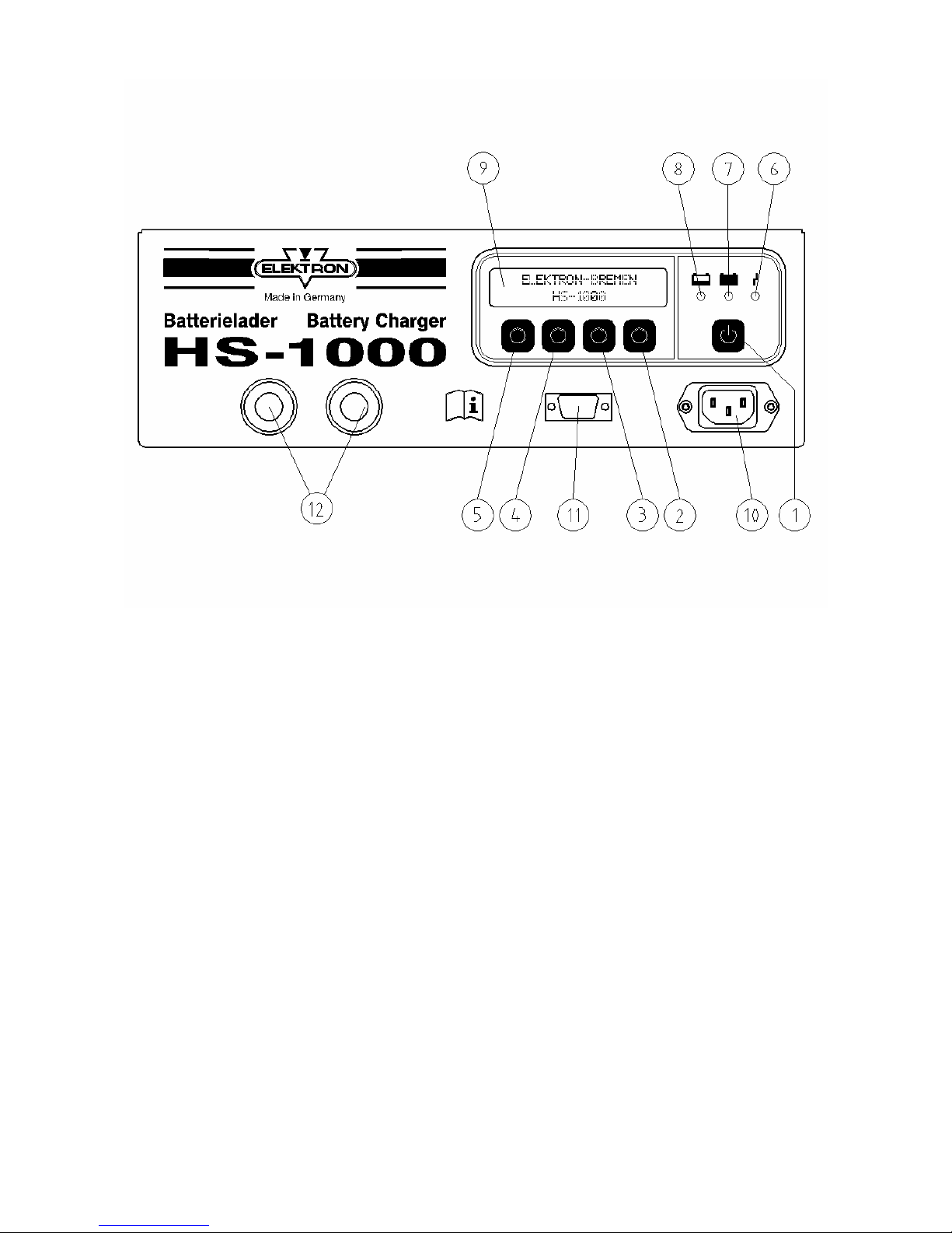
(1)
(2)
(3)
(4)
(5)
(6)
"ON/OFF" Button
"RUN/STOP" Button
+ menu-controlled functions
Button "Type of battery"
+ menu-controlled functions
"SET" Button
+ menu-controlled functions
"MENU" Button
+ menu-controlled functions
Fault indicator
glows red
(7)
(8)
(9)
(10)
(11)
(12)
Floating charge, illuminates
green when battery is charged
Charge control, lights up
yellow during charging
LC-Display
Cold appliance plug for mains
voltage
Serial interface RS 232
Charging cable, red clip (+),
black clip (-)
Page 3

- 3 -
Contents
1.0 Safety notes
2.0 Discription of the unit
3.0 Startup
3.1 Charging / trickle charge / floating mode
3.2 Backup mode (PSU-Auto) / PSU mode
4.0 Fault indication and troubleshooting /
technical data
6.0 Operation
6.1 Operating modes
6.1.1 Auto start feature
6.1.2 Charging 12V / 24V
6.1.3 Selecting battery / setting charging parameters / writing special
programs
6.1.3.1 Battery selection
6.1.4 Adaptation of charging parameters / writing special programs
6.1.5 External power supply (PSU) 12V + 24V
6.1.6 Support mode (PSU AUTO)
7.0 Service menu
7.1 General functions
7.2 Charging parameters
7.3 PSU parameters
8.0 Fault indication and troubleshooting
8.1 Temperature fault
8.2 Defective battery
8.3 Wrong battery
8.4 Reversed polarity
8.5 Reverse voltage
8.6 Output stage fault
8.7 Check sum error
9.0 Serial interface / firmware update
Page 4
- 4 -
1.0 Safety information
Î Connect only lead batteries with
rated voltage of 12 and 24 V!
Î Caution! Connect only
rechargeable batteries.
Î Caution! Explosive gases are
generated during charging of
batteries! Only charge batteries
in well ventilated areas.
Explosion hazard on account of
generation of oxyhydrogen gas!
Î Avoid all forms of fire, naked
light and sparking!
Î Wear protective goggles!
Î If acid splashes on to skin or
clothing, wash off immediately
with generous quantities of
water!
Î Caution!
If there is a pungent smell of gas,
acute explosion hazard is
present!
Î Do not switch the charger off!
Î Do not remove the charging
clips!
Î Thoroughly ventilate the area
immediately!
Î After adequate ventilation, switch
the charger off!
Î Check the battery!
Î Protect the charger from damp
and wet!
Î Install the charger such that the
air outlet is free!
Î Ensure stable location of the
charger!
Electrical safety:
Mains and charging cable must be in
perfect condition. If these cables are
damaged in any way, contact the
authorized workshop or your expert
dealer.
Replace defective leads and cables
immediately.
Working on the open
unit may only be done
by an authorized and
skilled expert!
Î Before start up of the unit read
the operating instructions
carefully.
Always operate the charger
according to these instructions.
Page 5

- 5 -
2.0 Description of the unit
The battery charger HS-1000 can be
used to charge 12V and 24V wet
batteries (also lead calcium) as well as
maintenance-free gel batteries, fleece
batteries or AGM-batteries.
(24 V functions disabled at factory!
Enabling possible in Service menu).
The appliance can also be used as an
external power supply (PSU) for motor
vehicles.
The HS-1000 battery charger is equipped
with a table-top housing. It is cooled by
free convection from bottom to top.
A fan is not used.
Ensure that the HS-1000 battery charger
is not covered up.
All connections as well as the displays
and controls are located on the front.
Display
While charging the momentary charging
current and the momentary charging
voltage are indicated on the LC Display
(9).
3 LEDs show the particular charging
status or fault:
Charging control (8) – Charging current
is flowing – see LCD-display (9).
Charge retention (7) – The battery is
charged. The charger has changed over
to holding the charge.
Fault (6) (see section 4.0)
Maximum charging current:
For 12 V: IN = 70 A
For 24 V: IN = 35 A
• For being charged the battery can
stay in the vehicle and does not
have to be disconnected from the
vehicle electrical system
• Absolute protection of the on-
board electronic system, as no
current and voltage peaks occur.
Backup mode (PSU Auto mode)
The charger replaces the vehicle battery
in case it has to be changed. The onboard voltage will be maintained.
PSU Mode
The charger operates as an external power
supply, supplying power to equipment and
systems in the vehicle and allowing them to
be tested.
Floating mode
The charger ensures that the battery is
reliably charged and the charge held,
even when consumers are connected up
to 70 A for 12 V or 35 A for 24 V.
Wrong polarity protection
The charger detects wrong polarity con-
nection and will not commence the
charging process. The red LED is on (6).
Release of clips
The charger reliably detects when the
clips are detached from the battery
during the charging process and switches
off.
Page 6

- 6 -
3.0 Start-up
Î Observe the precautions in the
safety notes!
Î Observe the handling instructions
of the battery manufacturer!
3.1 Charging / Charge retention/
Floating mode
• Determine type of battery
• Switch on unit with "ON/OFF" button
(1).
• Select battery present with button (3),
e.g. wet cell battery, AGM battery,
gelled battery, etc.
• Connect charging clips to battery
terminals with correct polarity. Red
clip (+) to the positive terminal, black
clip (-) to the negative terminal!
• If the charger is switched to the
automatic mode, charging / charge
retention starts automatically,
otherwise charging can be started by
pressing the "RUN" button (2).
• Caution! Does the charging voltage
set coincide with the battery voltage?
• The charging current and the
charging voltage are shown at the
LCD-display (9).
• The charging control lamp (8) lights
up.
• When the green LED "Charge
retention" (7) has illuminated for a
longer period of time the charger has
switched over to charge retention.
• If the battery is being discharged by a
consumer during floating operation,
the charger HS-1000 automatically
provides suitable charging.
• Floating mode can be carried out
during an unlimited period of time.
• Observe the maintenance
instructions of the battery
manufacturer.
• During the entire charging operation
or during charge retention, buffer
operation for the battery is possible.
If the battery is discharged by a load,
the HS-1000 battery charger supplies
the required current (within the limits
specified above).
Charging exhausted batteries/
Desulphation charging
• The charger surely detects
exhausted batteries.
• The charger will commence the
charging process carefully with low
charging current and will
subsequently adjust the charging
current to the battery condition.
Battery voltage has to be at least 0.6V!
3.2 Backup mode (PSU Auto) /
PSU Mode
• The Backup mode (PSU Auto)
provides a power supply buffer, for
example, when changing the battery,
so that important data and settings
are not lost.
The HS-1000 battery charger
automatically recognizes the voltage
required by the vehicle electrical
system and continues to supply this
voltage up to the maximum current
rating.
• Switch on the charger with the
"ON/OFF" button.
• Connect charging clips to battery
terminals with correct polarity. Red
clip (+) to the positive terminal, black
clip (-) to the negative terminal.
• Set the charger to the "PSU AUTO"
mode with button (5).
• Start operation with "RUN" button.
• The charging control lamp (8) lights
up. The charging current and the
charging voltage are shown at the
LCD-display (9).
Page 7

- 7 -
• This mode remains set until it is
deactivated with the "STOP" button.
• In the PSU Mode the charger
operates only as a battery reversevoltage, i.e. when this mode is
selected power is always present on
the battery clips.
Caution! Danger of short circuit!
• Switch the charger on with the
ON/OFF button.
• Caution! Never allow the charging
clips to come into contact with one
another!
• Select "PSU" mode with button (5).
• Start operation with "RUN" button.
• The charging control lamp (8) lights
up. The charging current and the
charging voltage are shown at the
LC-Display (9).
• This mode remains active until it is
discontinued with the "STOP" button.
Before disconnecting the
charging clips always
switch of the charger with
the ON/OFF button.
4.0 Fault indication and
troubleshooting
Fault indicator (6) flashes:
• If temperature of unit is too high
• If charging clips have been
connected with wrong polarity
• When battery voltage is too high
• If the battery connected is defective:
The fault is indicated on the LC
Display
The fault display extinguishes after
elimination of the fault.
Fault indicator (6) illuminates with steady
light:
• There is a system fault in the
charger. The fault is simultaneously
indicated on the LC Display
• Switch off the charger with the
ON/OFF button.
If the fault is still present after
switching the charger back on,
contact the authorized workshop or
your expert dealer.
Page 8

- 8 -
5.0 Technical data
Mains voltage 90 - 260 V
Mains frequency 50/60 Hz
Nominal voltage
12 V and 24 V
lead-acid batteries
Constant voltage 2.4 / 2.35 V/cel
Charging current 70 A and 35 A
Charging
characteristic
IUoU
Protection type IP 54
Metal housing
(W x H x D in mm)
325x120x406
Weight 6.5 kg
Length of charging
cable (incl. clips)
5 m
Length of mains
cable
2.5 m
Interface RS 232
Subject to technical changes without prior notice
The HS-1000 Battery Charger
complies with the requirements of the
automotive industry and in particular
fulfils EN 60335, IEC 801 and EN 55011
Page 9

- 9 -
6.0 Operation
The HS-1000 battery charger offers a
variety of features and settings. The
operating structure is clearly arranged,
allowing the charger to be operated
intuitively. Clarity is achieved primarily by
using softkeys. This means that the
functions of keys (1) – (4) are determined
freely by the unit software depending on
the specific menu. These assignments
are indicated in the bottom line of the
display above the keys.
------------------- xxx xxx xxx xxx
6.1 Operating modes
6.1.1 Auto start feature
The HS-1000 battery charger is equipped
with an automatic start feature. The
charger automatically starts the selected
function immediately after pressing the
ON/OFF button without having to start
this function separately. The "12 V
Charging" function is set as default. If
a battery is not connected, the charger
remains ready for operation in the
standby mode:
1-0 CH STANDBY 12V
MENU SET WET
The charging operation starts after a
battery is connected.
If the charging operation is interrupted by
a clip coming off, the charger
immediately switches back to the standby
mode. Charging starts again when a
battery is reconnected.
In the event of a power failure (or if the
plug is disconnected) the charger
automatically resumes charging when the
power returns.
Discontinuation of the charging operation
with the "STOP" button switches off the
auto start feature. Then it is necessary to
start every further charging operation "by
hand" with the "RUN" button. Switching
the charger off and then back on with the
ON/OFF button reactivates the auto start
feature, etc.
The auto start feature can always be
switched off by pressing the "MENÜ“
button.
All charger operating modes can be set
as the auto start mode (See Chap. 7.1
"General Functions")
6.1.2 Charging 12V / 24V
The battery is charged according to an
IUoU curve, meaning that charging is
accomplished during the initial at the
maximum possible current until the
voltage threshold of 14.4V (28.8V) is
reached. This voltage is then kept
constant for 6h, after which the charger
switches over to charge retention with the
voltage maintained at 13.3V (26.6V).
The following display appears while
charging:
Ub:11.2V Ib:70.0A
INFO STOP
z
Page 10

- 10 -
The momentary battery voltage Ub and
charging current Ib are indicated
permanently in the upper line.
Pressing the "INFO“ button displays the
charging time already expired as well as
the quantity charged. The display
automatically returns to the standard
display after 3 s.
00:00:25h 2.5 Ah
INFO STOP
z
After the battery is completely charged
the charger switches over to retention
charging.
BATTERY CHARGED
INFO STOP
z
The current charging voltage is indicated
at intervals of 5s.
Ub:13.3V
INFO STOP
z
The charging operation can be
terminated at any time by pressing the
"STOP" button.
The charger then returns to the basic
menu "Charging".
1-0 CHARGE 12V
MENU SET WET RUN
6.1.3 Selecting battery / setting
charging parameters / writing
special programs
Various settings can be made in the main
menu. It is possible to select different
types of batteries, change the charging
curve parameters and save your own
special programs.
6.1.3.1 Battery selection
Button (3) allows selection of different
types of specified batteries with fixed
parameters or to select special programs
you have written yourself (see below).
The following types of batteries can be
selected:
WET
For batteries with liquid electrolyte
(including lead/calcium batteries)
AGM
For batteries with electrolyte
absorbed in a glass mat (Absorbed
Glass Matt)
GEL
For batteries with gelled electrolyte
The proper charging curve parameters
are loaded automatically to match the
type of battery selected:
WET AGM GEL
U1 14.4 V 14.4 V 14.1 V
U2 13.3 V 13.3 V 13.3 V
Ia max 70 A 70 A 70 A
t in U1 6 h 6 h 6 h
Page 11

- 11 -
6.1.4 Adapting charging parameters /
writing special programs
The four parameters listed above can be
adapted to the specific requirements with
the "SET" button.
First the value for the constant voltage
U1 appears:
1-1 VOLTAGE 14.4V
OK + -
Press the "+" and "–“ buttons to change
the value in increments of 0.1 V.
Press the "OK" button to continue to the
next parameter, the value for the charge
retention voltage U2:
1-2 FLOATING 13.3V
OK + -
Set in the same manner.
Press "OK" to go to the parameter
"maximum output current“ Ia max:
1-3 Ia max 70.0A
OK + -
The value can be changed in increments
of 0.1A.
Press "OK“ to continue to the parameter
for duration of constant voltage charging
at U1:
1-4 TIME: 6h00m
OK + -
The value can be changed in increments
of one minute.
The changes made can only be stored in
the "TMP" memory temporarily, i.e. until
the ON/OFF button is pressed the next
time.
STORE IN TMP
OK + -
However permanent storage in special
programs S1, S2 or S3 is also possible
with the "+“ and "–“ keys.
The save operation can be confirmed
with the "OK" button or the entire
procedure can be aborted with the "ESC"
button. Successful storage is confirmed
by the display "SAVED“. The display then
returns to the basic menu "Charging"
Please Note:
Changes made become active only when
selected in the basic menu. For this
purpose select again with button (3).
For temporary changes select "TMP“, for
permanently stored settings select "S1“,
"S2“ or "S3“.
Page 12

- 12 -
1-0 CHARGE 12V
MENU SET TMP RUN
Naturally one of the standard settings
("WET“, "AGM“, or GEL“) can also be
selected now; the changes remain stored
in "TMP" until the charger is switched off.
The changing operation can then be
started with the modified parameters by
pressing the "RUN" button.
The procedures described above are
identical for the 12V Charging and 24V
Charging functions.
This mode is provided for vehicles
without a battery, for example in a display
room at a dealership. The charger
provides a previously set output voltage
up to the maximum output of the charger
whereby the maximum output current can
also be set.
The procedures described here are
identical for the 12V PSU and 24V PSU
functions.
3-0 PSU 12V
MENU SET DFT RUN
The default setting "DFT" is given in the
basic menu.
Ua = 13.4 V (26.8V)
Ia max = 70.0 A (35.0A)
This default cannot be changed.
However it is possible to switch to the
adjustment mode by pressing the "SET"
button. First it is possible to set the
output voltage.
3-1 VOLTAGE 13.4V
OK + -
Press the "OK“ button to set the
maximum output current.
3-2 Ia max 70.0A
OK + -
This setting can be saved temporarily in
the "TMP“ memory. However permanent
storage in special programs S1, S2 or S3
is also possible with the "+“ and "–“ keys.
STORE IN TMP
OK ESC + -
6.1.5 External Power Supply (PSU)
12V + 24V
Page 13

- 13 -
The save operation can be confirmed
with the "OK" button or the entire
procedure can be aborted with the "ESC"
button. Successful storage is confirmed
by the display "SAVED“. The display then
returns to the basic menu "PSU".
Please Note: Changes made become
active only when selected in the basic
menu. For this purpose select again with
button (3).
For temporary changes select "TMP“, for
permanently stored settings select "S1“,
"S2“ or "S3“ (or the default setting "Std").
The charger can then be started with the
modified parameters by pressing the
"RUN" button.
PSU 13.2V 20.3A
STOP z
The momentary values for the output
voltage and the output current are
permanently visible on the display.
This function is continues for an unlimited
time, however can be stopped at any
time with the "STOP" button.
6.1.6 Support mode (PSU AUTO)
This mode supports the vehicle battery
(by providing a buffer) during
demonstrations and prevents loss of data
in the vehicle control systems when the
battery is replaced. The charger
automatically recognizes the correct
voltage for the vehicle electrical systems
and maintains it up to the maximum
output capacity of the charger.
5-0 PSU AUTO
MENU SET RUN
The possibilities for adjustment are
limited here to the maximum output
current.
5-1 Ia max 70.0A
OK + -
Any change made can be confirmed with
the "OK“ button and remains permanently
stored, i.e. the next time the charger is
switched on the value set here is used
again.
The charger can then be started with the
modified parameters by pressing the
"RUN" button.
PSU AUTO: 13.2V 20.3A
STOP z
This function is continues for an unlimited
time, however can be stopped at any
time with the "STOP" button.
Page 14

- 14 -
7.0 Service menu
This menu allows setting to be made,
which affect the basic function of the
charger. Here it is possible to define
limits for the setting ranges, select the
language for the displays or set the auto
start feature.
6-0 SERVICE
MENU
This area is not accessible for normal
users.
However the menu can be activated by
pressing buttons (2) und (3)
simultaneously.
6-0 SERVICE
MENU GLO CHR PSU
7.1 General functions
When the "GLO“ button is pressed the
charger switches to the submenu for
global settings. Here it is also possible to
read out the fault memory or restore the
default settings.
First it is possible to define the auto start
feature.
6-11 START CHARG 12V
OK + -
One of the following functions can be
selected with the "+“ und "–“ buttons:
12V Charging
24V Charging
12V PSU
24V PSU
PSU Auto
The desired auto start function can be
confirmed with the "OK" button.
Simultaneously the charger switched to
the next menu item "Language".
6-12 LANGUAGE: D
OK
+ -
One of the following languages can be
selected with the "+“ und "–“ buttons:
"D“ = German
"GB“ = English
"F“ = French
"NL“ = Dutch
"E“ = Spanish
"I“ = Italian
The display texts are then switched over
to the language selected.
Confirm selection with the "OK“ button.
The display then continues to the next
menu point "Fault memory".
Page 15

- 15 -
6-13 F1 0x0000
OK + -
The last ten fault messages F1 through
F10 can be viewed by pressing the "+“
and "–“ keys. They are output in
hexadecimal numerical format. The
meaning of the most important codes is
explained in Chap. 8.
The last menu point allows the charger
settings to be returned to the default
settings (made at the factory):
6-14 DEFAULT? NO
OK ESC Y/N
The default answer here is "No",
meaning that the charger is not set back
to the default settings when the "OK"
button is pressed. It is possible to switch
to "Yes" with the "Y/N" button.
The service menu can be aborted
completely pressing the "ESC" button
and the program returns to the basic
menu "SERVICE".
When the "OK“ button is pressed, the
charger again asks if the changes made
are to be saved:
Save?
OK ESC
The changes can be saved by pressing
the "OK" button again. Press the "ESC“
button to delete the changes; the
program returns to the basic menu
"SERVICE“.
7.2 Charging parameters
6-0 SERVICE
MENU GLO CHR PSU
When the "CHR" button is pressed the
charger switches to the submenu
"Charging function". Here it is possible to
define limits for the adjustment ranges for
the charging parameters. This makes it
possible to allow changes to the charger
settings only within extremely close limits
to prevent damaging particularly sensitive
components in the vehicle with improper
settings.
It is also possible to completely disable
the 24V function.
Caution: The changes made here are
not monitored by the software! Avoid
absurd or damaging settings under all
circumstances!
Page 16

- 16 -
6-2 CHARGE MODE
ESC 12V 24V
Press the "ESC“ button to return to the
basic menu "SERVICE“.
Pressing the "12V“ button causes the
charger to switch to the 12V parameter
limits.
First the minimum limit for the
adjustment range for the constant voltage
U1:
6-211 U1 min 13.2V
OK + -
This value can be adjusted with the "+“
and "–“ keys.
Press the "OK“ button to continue to the
next parameter in the following
sequence:
U1 max
U2 min
U2 max
Ia max
The values are then saved. However this
operation can be circumvented by
pressing the "ESC" button. The charger
returns to the basic menu "SERVICE“.
From here it is possible to go to the 24V
parameter range by pressing the "24V"
button.
Here the settings can be made in the
same manner as described for 12V.
However observe the following special
feature:
The following question appears as the
final subpoint:
6-276 RELEASE YES
OK + -
It is possible to switch back and forth
between "Yes" and "No" with the "+“ and
"–“ keys. After confirmation with the "OK“
button the 24V function is enabled or
disabled.
Another question appears for final
storage:
STORE ?
OK ESC
The changes can be saved by pressing
the "OK" button again. Press the "ESC“
button to delete the changes; the
program returns to the basic menu
"SERVICE“.
7.3 PSU parameters
6-0 SERVICE
MENU GLO CHR PSU
Page 17

- 17 -
When the "PSU" button is pressed the
charger switches to the submenu "PSU
function" Here it is possible to define
limits for the adjustment ranges for the
external power supply parameters. This
makes it possible to allow changes to the
charger settings only within extremely
close limits to prevent damaging
particularly sensitive components in the
vehicle with improper settings. It is also
possible to completely disable the 24V
function.
Caution: The changes made here are
not monitored by the software! Avoid
absurd or damaging settings under all
circumstances!
6-3 PSU MODE
ESC 12V 24V
Press the "ESC“ button to return to the
basic menu "SERVICE“.
Pressing the "12V“ button causes the
charger to switch to the 12V parameter
limits.
First the upper limit for the output voltage
adjustment range:
6-311 Ua max 16.0V
OK + -
Pressing the "OK“ button switches to the
next parameter, the maximum value for
the output current.
6-312 Ia max 70.0A
OK + -
The values are then saved. However this
operation can be circumvented by
pressing the "ESC" button. The charger
returns to the basic menu "SERVICE“.
From here it is possible to go to the 24V
parameter range by pressing the "24V"
button.
Here the settings can be made in the
same manner as described for 12V.
However observe the following special
feature:
The following question appears as the
final subpoint:
6-276 RELEASE YES
OK + -
It is possible to switch back and forth
between "Yes" and "No" with the "+“ and
"–“ keys. After confirmation with the "OK“
button the 24V function is enabled or
disabled.
Another question appears for final
storage.
Page 18

- 18 -
8.0 Fault indication /
trouble shooting
The fault codes (see Chap. 7.1) are
given in the titles below.
8.1 Temperature fault (0x0020)
TEMPERATURE
z z
Explanation:
To prevent the charger from overheating
the output is reduced in a number of
stages when the temperature increases
above a critical value. If the maximum
value is exceeded in spite of this
reduction in the output, the charger
switches off and the fault message above
appears. After an appropriate cooling
phase, the charging operation is
continued.
Remedy:
Charger covered by rags, paper, etc.
Remove all objects, which could cover
the ventilation slits.
8.2 Defective battery (0x0200)
DEFECTIVE BATTERY
OK z
Explanation:
If the battery voltage does not reach a
minimum voltage of 12V (24V) within 30
minutes, the charging operation is
aborted with this error. Only a defective
battery (short circuit between cells, etc.)
behaves in this manner.
Remedy:
Replace battery.
8.3 Wrong battery (0x0100)
WRONG BATTERY
OK z
Explanation:
The battery voltage goes beyond a
maximum value of 17.4V (38.8V) during
the initial charging phase or increases to
beyond a maximum limit of 15.5V (31V)
while charging.
Remedy:
Battery connected has incorrect voltage
rating. Replace battery or adapter
charger setting
8.4 Reversed polarity (0x0400)
WRONG POLARITY
OK
z
Page 19

- 19 -
Explanation:
The charging clips were connected to the
wrong poles.
Remedy:
Connect charging clips to battery
terminals with correct polarity:
Red clip (+) to positive pole; black clip (-)
to negative pole.
8.5 Reverse voltage (0x0800)
EXTERNAL VOLTAGE
OK
z
Explanation:
A voltage was detected in the vehicle
electrical systems in the PSU mode. The
PSU mode is not intended for such
cases.
Remedy:
Use the PSU Auto function.
8.6 Output stage fault (0x0040)
PU ERROR
z
Explanation:
The output stage did not react as
expected by the control. A hardware fault
is present.
Remedy:
The charger is defective. Switch it off with
the ON/OFF button.
Contact the service department.
Art.- No. 326 695 (Englisch)
8.7 Check sum error (0x0008)
RESTORE DEFAULT VALUES
z
Explanation:
An error is present in the data memory
(data loss, memory defective)
Caution:
The charger tuning is lost!
Please contact the service
department, the charger is no longer
in an operating state!
9.0 Serial interface /
firmware update
The charger is equipped with a serial
interface (RS232) . The associated
socket (11) is located on the front of the
charger (9-pin, Sub D).
If a software update is required, the
firmware can be updated easily using the
corresponding software and a PC or
laptop connected to this interface.
12/07
 Loading...