

Elektra Beckum mig mag 232 ep, mig mag 302 ep, mig mag 502 ep, mig mag 402 ep Operating Instructions Manual
Page 1
S0021IVZ.fm
A
V
MIG MAG 232 EP
MIG MAG 302 EP
MIG MAG 402 EP
MIG MAG 502 EP
Betriebsanleitung. . . . . . . . . . . . . . . . . . . . .3
Operating Instruction . . . . . . . . . . . . . . . . .12
Instructions d’utilisation . . . . . . . . . . . . . . .20
Handleiding . . . . . . . . . . . . . . . . . . . . . . . .29
Manuale d’istruzioni. . . . . . . . . . . . . . . . . .38
Manual de uso. . . . . . . . . . . . . . . . . . . . . .47
115 167 6789 / 1701 - 1.1
Page 2

Ê
ÖRSÄ
U2S0021.fm
D DEUTSCH ENG ENGLISH
KONFORMITÄTSERKLÄRUNG DECLARATION OF CONFORMITY
Wir erklären in alleiniger Verantwortlichkeit, dass dieses Produkt mit
den folgenden Normen übereinstimmt* gemäß den Bestimmungen der
Richtlinien**
F FRANÇAIS NL NEDERLANDS
DECLARATION DE CONFORMITE CONFORMITEITSVERKLARING
Nous déclarons, sous notre seule responsabilité, que ce produit est en
conformité avec les normes ou documents normatifs suivants* en vertu
des dispositions des directives **
IT ITALIANO ES ESPAÑOL
DICHIARAZIONE DI CONFORMITÀ DECLARACION DE CONFORMIDAD
Noi dichiariamo sotto la nostra esclusiva responsabilità che il presente
prodotto è conforme alle seguenti norme* in conformità con le
disposizioni delle normative **
We herewith declare in our sole repsonsibility that this product
complies with the following standards* in accordance with the
regulations of the undermentioned Directives**
Wij verklaren als enige verantwoordelijke, dat dit product in
overeenstemming is met de volgende normen*
conform de bepalingen van de richtlijnen**
Declaramos bajo nuestra exclusiva responsabilidad, que el presente
producto cumple con las siguientes normas* de acuerdo a lo dispuesto
en las directrices**
PT PORTUGU
DECLARAÇÃO DE CONFORMIDADE
Declaramos sob nossa responsabilidade que este produto está de
acordo com as seguintes normas* de acordo com as directrizes dos
regulamentos **
FIN SUOMI NO NORGE
VAATIMUKSENMUKAISUUSVAKUUTUS SAMSVARSERKLÆRING
Vakuutamme, että tämä tuote vastaa seuraavia normeja* on
direktiivien määräysten mukainen**
DA DANSK POL POLSKI
OVERENSSTEMMELSESATTEST OŚWIADCZENIE O ZGODNOŚCI
Hermed erklærer vi på eget ansvar, at dette produkt stemmer overens
ed følgende standarder* iht bestemmelserne i direktiverne**
EL ΕΛΛHNIKA HU MAGYAR
∆ΗΛΩΣΗ ΑΝΤΙΣΤΟΙΧΕΙΑΣ MEGEGYEZŐSÉGI NYILATKOZAT
∆ηλώνουµε µε ιδία ευθύνη ότι το προϊόν αυτό αντιστοιχεί στις
ακόλουθες προδιαγραφές*
σύµφωνα µε τις διατάξεις των οδηγιών**
S SV SVENSKA
KRAN OM ÖVERENSSTÄMMELSE
F
Vi försäkrar på eget ansvar att denna produkt överensstämmer med
följande standarder* enligt bestämmelserna i direktiven**
Vi erklærer under eget ansvar at dette produkt samsvarer med
følgende normer* henhold til bestemmelsene i direktiv**
Oświadczamy z pełną odpowiedzialnością, że niniejszy produkt
odpowiada wymogom następujących norm* według ustaleń
wytycznych **
Kizárólagos felelősségünk tudatában ezennel igazoljuk, hogy ez a
termék kielégíti az alábbi szabványokban lefektetett követelményeket*
megfelel az alábbi irányelvek előírásainak**
MIG MAG 232 EP, MIG MAG 302 EP, MIG MAG 402 EP, MIG MAG 502 EP
* EN 60974-1
** 98/37/EG, 73/23/EWG, 89/336/EWG, 93/68/EWG
Jürgen Kusserow
Vorstand
ELEKTRA BECKUM AG – Daimlerstraße 1 – 49716 Meppen
1001004/ 01
2
Page 3

Xs0014e.fm Operating Instruction ENGLISH
ENGLISH
Table of Contents
1. Please Read First!.....................12
2. Safety .........................................12
2.1 Specified conditions of use .........12
3. Operating Elements..................13
3.1 Powerbox
(welding power source)...............13
3.2 SDV (separate wire feed unit).....13
3.3 SWK
(separate watercooling unit)........13
3.4 Control unit..................................13
3.5 Control unit for default
machine settings.........................14
4. Installation.................................14
5. Transport ...................................14
5.1 Crane hoisting.............................14
6. Preparing for Operation............14
6.1 Manual arc welding.....................14
6.2 Gas-shielded arc welding............14
6.3 Threading the electrode
wire in.............................. ... .........15
6.4 Connect the gas cylinder.............16
7. Default Machine Settings .........16
7.1 Control unit for default
machine settings.........................16
7.2 Charateristics curves...................16
7.3 Gas type......................................16
7.4 Pulsed MIG/MAG........................16
7.5 MIG/MAG....................................16
7.6 Manual arc welding.....................16
7.7 FBZ Burnback time .....................16
8. Operation...................................17
8.1 Control unit..................................17
8.2 Gas-shielded arc welding............17
8.3 Manual arc welding.....................17
8.4 Shutting down .............................17
9. Maintenance ..............................17
10. Available Accessories..............17
11. Repairs.......................................18
12. Environmental Protection ........18
13. Troubles.....................................18
13.1 Error messages...........................18
13.2 General faults..............................18
14. Technical Specifications..........19
15. Available Accessories..............59
1. Please Read First!
• Read these instructions before use.
Pay special attention to the safety
information.
• If you notice transport damage while
unpacking, notify your supplier
immediately. Do not operate the
machine!
• Dispose of the packing in an environmentally friendly manner. Take
to a proper collecting point.
• Keep these instructions for reference on any issues you may be
uncertain about.
• If you lend or sell this machine be
sure to have the instructions go with
it.
2. Safety
All legal regulations pertaining to the
operation of electric arc welding
machines must be observed.
The following information should be
observed as well for a safe and risk-free
handling of the welding machine!
Danger! Electric potential!
− Use the machine indoors and in dry
environment only.
− Connect the machine only to an
properly earthed out.
If in doubt check with a qualified
electrician!
Danger! Electric potential!
Service and repairs to the machines
must only be made by qualified electricians.
Unplug before removing the machine’s
cover.
Danger!
Wear sufficient protective clothing when
welding.
Always use a welding visor and welder’s
gloves to protect against flying sparks
and arc radiation.
Danger!
All metal fumes are detrimental to
health!
When working indoors ensure sufficient
ventilation and extraction in order to not
exceed the max. permissible workplace
pollutant concentration.
Fumes of lead, cadmium, copper, zinc
and beryllium are especially harmful!
Caution!
Never weld earthed metal.
Welding earthed metal may cause possible damage to the protective earth conductors by stray currents.
Caution!
Always attach the earth cable directly to
the weld metal and as close as possible
to the welding spot.
Caution!
Special care is required when working
near computers, electronically controlled
equipment or in the proximity of magnetic data media (sound recording
tapes, floppy disks, data recording
tapes, credit cards, etc.).
The arc start can cause misfunction of
this type of equipment or data loss.
2.1 Specified conditions of
use
The following components
− Powerbox (welding power source)
− SDV (separate wire feed unit)
− SWK (separate watercooling unit,
optional available for models 232/
302 EP at extra cost)
together constitute are complete welding
machine for professional and industrial
use.
Note:
The componenents, connected to
each other and ready to run are referred
to as "welding machine" in these instructions.
Their most important features:
− Secondary-switched inverter for
gas-shielded arc welding
− Integrated manual arc welding mode
− Gas-shielded arc welding with pre-
programmed charateristics curves
− Integrated charateristics curve for
MIG brazing
− 4-roller drive with tachometer-controlled motor for precise and reliable
wire feed
− Integrated softstart for operating
modes MIG/MAG and pulsed MIG/
MAG
− Water cooling for high shielding gas
welding power.
This welding machine is intended for
welding FE-metals, alloyed steels, nonferrous heavy metals and aluminium.
It conforms to all relevant regulations at
the time of delivery.
This welding machine is intended for
operation by professional arc weldors or
specialists with similar qualification.
Permissible welding processes:
− MIG and pulsed MIG (Metal-InertGas),
for aluminium and aluminium alloys
− MAG and pulsed MAG (MetalActive-Gas)
for steel or stainless steel
− Manual arc welding
for steel
− MIG brazing
for electro-galvanized steel plates.
For TIG welding it must be ensured that
the shielding gas cover is not blown
away by air draft.
12
Page 4
ENGLISH
A
V
For machine performance see "Technical Specifications".
Any other use is not as specified and
prohibited.
The manufacturer is not liable for any
damage caused by unspecified use.
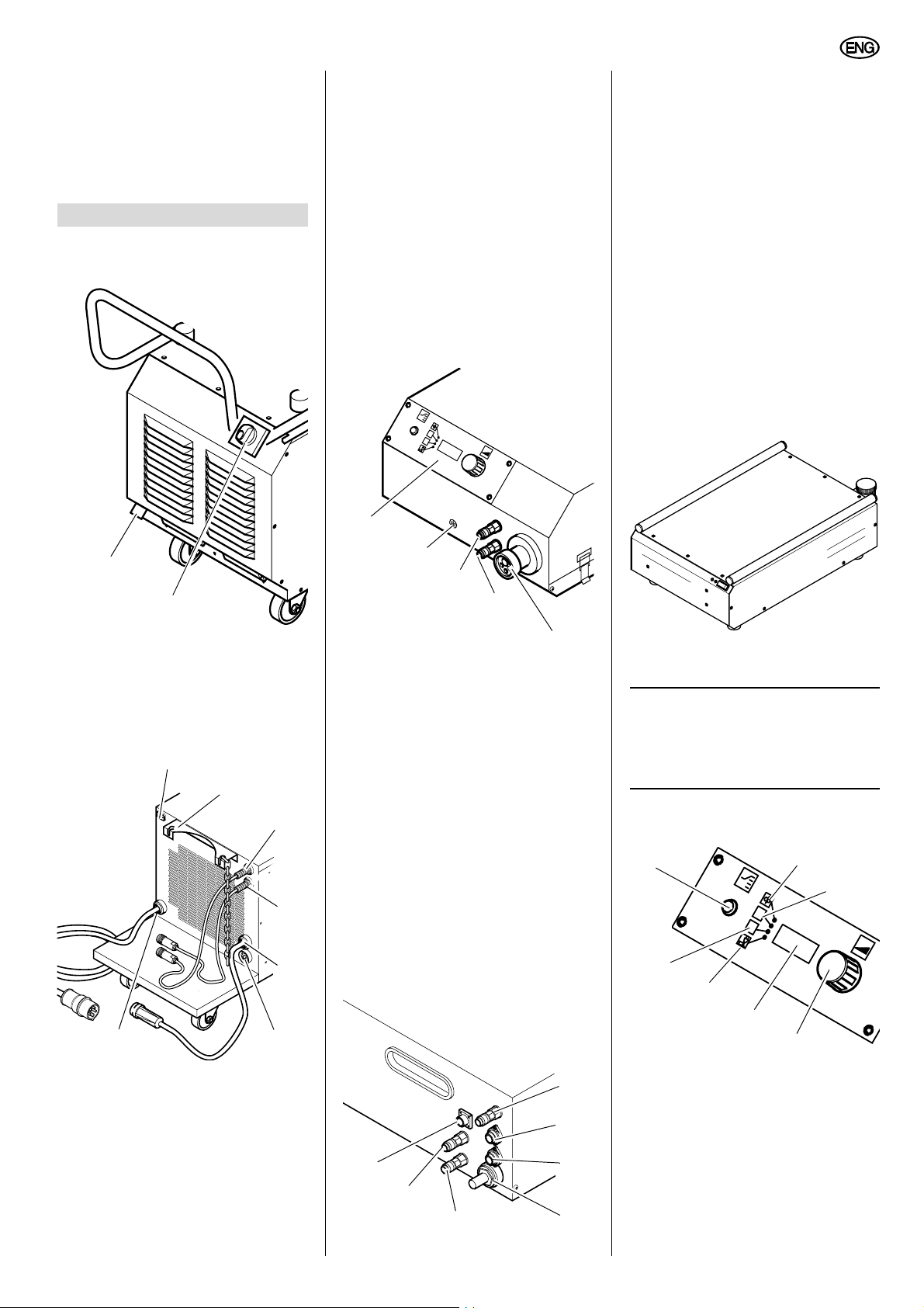
3. Operating Elements
3.1 Powerbox
(welding power source)
6 Power cable
SDV motor. When using a SWK the
power supply cable is connected to
the SWK. The SDV then automatically controls the water cooling
when welding.
7 Welding cable
with cable connector (+ pole).
8 Connection (rear) for earth cable
(- pole).
9 Power supply cable
with CEE plug.
3.2 SDV (separate wire feed
unit)
14
15 Connection for shielding gas
line
16 Connector socket for exteral
programming
17 Connector socket for power sup-
ply
18 Connector plug for welding cur-
rent supply
19 Connection for coolant runback
into SWK.
20 Connection for coolant feed from
SWK.
21 Connector socket for pilot lead
3.3 SWK (separate watercooling unit)
1
2
1 Connection (front) for earth
cable (- Pole).
2 Main switch
switches the Powerbox and all
devices connected to it ON or OFF.
3
4
13
12
11
10
The SWK is automatically controlled by
the Powerbox.
10 Euro connector socket for weld-
ing gun
for connection of all commercially
available welding guns.
11 Connection for coolant runback
from welding gun.
Note:
Instructions on how to connect
and operate the SWK are given in the
separate instructions supplied with the
device.
12 Connection for coolant feed to
5
welding gun.
13 Connector socket for pilot lead
of external devices.
14 Control unit.
6
7
Selection, display and setting of the
operating parameters.
The control unit for the machine’s
default settings is located inside the
SDV.
3.4 Control unit
22
A
V
25
23
24
26
98
3 Power supply outlet for addi-
tional devices
Rating: 10 A / 230 V.
4 Bracket with chain
secures the gas cylinder against
turning over.
5 Pilot lead
for SDV.
21
20
19
15
16
17
18
27
28
22 Parameter selection (momen-
tary contact switch)
for selection of the parameter to be
displayed and/or adjusted.
The LEDs [
selected parameter.
23-26] indicate the
23 LED wire feed [m/min]
24 LED welding current [A]
13
Page 5

ENGLISH
LED welding voltage [V]
25
26 LED arc length [%]
27 7-segment display (3 digits)
The display shows:
− the value of the selected
parameter or
− an error message.
28
Parameter adjustment
to adjust the selected parameter.
3.5 Control unit for default
machine settings
29 30
34
33
31
32
4. Connect the cables as illustrated
below.
1. Fit the hoisting straps as illustrated
below.
A
V
Caution!
At the workplace, secure the
machine against rolling away.
29 Wire thread-in button
(Manual Wire Feed Drive)
30 Operating mode selector switch
(Mode Selection)
31 Burnback time selector switch
(Wire burnback control)
32 Gas type selector switch
(Gas Type)
33 Wire diameter selector switchr
(Wire Diameter)
34 Wire type selector switch
(Wire Type)
4. Installation
The individual components need to be
connected to each other before being
connected to the mains and before inital
operation. By default the components as
set for gas-shielded arc welding:
1. With the help of another person lift
the SWK (water cooling unit) and
place it on the Powerbox, to that its
feet stand between the pipes on the
rubber mat.
2. With the help of another person lift
the SDV (wire feed unit) and place it
onto the water cooling unit.
3. Connect the coolant hoses as illustrated below (see also the SWK
instructions).
14
5. Transport
The Powerbox is mounted on a wheel
set. With fitted SDV and SWK the complete welding machine is conveniently
moved to the workplace.
Danger!
Close the cylinder’s valve
before relocating.
Danger!
Note the hight weight of the
welding machine. It may get out of
control, especially on sloping
ground!
Walk along the intended way, before
you set off with the welding machine.
Ask another person for assistance, if
necessary!
5.1 Crane hoisting
The welding machine can be hoisted by
crane.
Danger!
Remove the gas cylinder
before hoisting.
Hoisting with the gas cylinder is forbidden!
6. Preparing for Operation
6.1 Manual arc welding
When setting the machine for manual
arc welding, you must:
1. Check all connections.
Disconnect earth cable (- pole) and
welding current supply cable
(+ pole).
2. Connect earth cable to the Powerbox - pole).
3. Connect welding cable to the welding current supply cable (+ pole).
6.2 Gas-shielded arc welding
1. Check all connections. Disconnect
earth cable (- pole).
The welding current supply cable
(Powerbox) must be connected to
the connector plug of the welding
current supply (SDV).
Page 6

ENGLISH
1
2
3
4
5
1
2
3
4
5
1
2
3
4
5
1
2
3
4
5
1
2
3
4
5
2. Connect earth cable to the Powerbox - pole).
3. Check coolant level of the SWK.
Note:
Refer to separate instructions
supplied with the device.
4. Connect the welding gun to the
SDV’s Euro connector socket.
5. Connect coolant hoses according to
their colour coding.
A
V
6. Install electrode wire spool:
− Open SDV cover.
− Remove the arbor cap from the
spool carrier arbor and place the
electrode wire spool on the spool
carrier arbor.
− The driving pin (35) must fit into
the wire roll’s driving hole.
− Put the arbor cap back on.
Check setting of brake, correct
with screw (36) if necessary. The
brake prevents post-running of
the wire roll when the welding
process stops.
36
6.3 Threading the electrode
wire in
1,0/1,2 mm oder 0,6/0,8 mm.The feed
rolls are grooved for 1.0/1.2 mm or 0.6/
0.8 mm wire diameter. In operation the
electrode wire runs through the rear
groove (on the motor side). The wire
feed drive is factory-set for 1.0 mm electrode wire.
If 1.2 mm electrode wire is to be used
the feed rolls must be reversed, for 0.6/
0.8 mm electrode wire the correspond-
ing feed rolls must be fitted.
38
37
− Loosen retaining screws (37).
− Pull the feed rolls (38), complete
with gearwheels, off the floating
axles.
− Lift the feed roll off the gearwheel
and put it back on in a reversed
position, or replace with a feed
roll of appropriate groove size.
− Put both parts back onto the
floating axle and secure with the
retaining screw.
3. Deburr the electrode wire and run it
− through the spiral guide,
− over the rear feed roll,
− through the guide tube,
− over the front feed roll
− into the Euro connector socket.
4. Close pressure roll brackets and
swing handles up.
Set the contact pressure of the front
feed roll a little higher than that of
the rear feed roll.
5. Remove gas shroud and contact tip
from the welding gun’s swan neck.
39
6. Switch all devices ON keep the wire
1. Swing handles outwards. The pressure roll brackets will swing up.
2. Check position of the feed rolls,
reverse rolls if necessary:
thread-in button on the SDV (39)
pressed down, until the electrode
wire projects approx. 2 cm at the
swan neck.
7. Replace contact tip and gas shroud.
8. Close the SDV cover.
35
15
Page 7

ENGLISH
6.4 Connect the gas cylinder
1. Place gas cylinder on Powerbox and
secure with chain against turning
over.
40
2. Connect gas hose to the SDV (40).
Note:
The SDV is fitted with a solenoid
valve. Gas flows only during the welding
process.
3. Connect gas hose to pressure regu-
lator.
7. Default Machine Settings
7.1 Control unit for default
machine settings
1. Open SDV cover.
2. Stipulate the welding process set-
tings with the selector switches:
− the type of electrode wire (Wire
Type)
− the wire diameter (Wire Diameter)
− the type of shielding gas (Gas
Type)
− the operating mode (Mode Selection)
− the burnback timer (Wire burnback control).
7.2 Charateristics curves
The default charateristics curves, supplied with the machine, are selected by
the settings made at the control unit for
the default machine settings.
Example: Charateristics curve for
MIG brazing
MIG brazing is suitable for brazing galvanized sheet metal. To select this charateristics curve, the following settings
must be made.
Wire type: Cu/CuZn
Gas type: I1 (Argon) or
M12 (0-5% CO2,
balance Argon)
Operating mode: MIG/MAG or
pulsed MIG/MAG.
Note:
The allocation of settings and
corresponding charateristics curves is
shown on the label affixed to the inside
of the cover.
As an option, any charateristics curve
can be changed by a PC via the connector socket for programming.
Note:
Detailed information about programming of characteristic curves is
available from the service centre in your
country (see address listing on back
cover of the spare parts list).
The operating mode PROGRAMM is
reserved for charateristics curve programming.
7.3 Gas type
I1 = 100% Argon
M13 = 0-3% O2, balance Argon
M12 = 0-5% CO2, balance Argon
M21 = 0-25% CO2, balance Argon
7.4 Pulsed MIG/MAG
2-step = manual welding operation:
1. Actuate the torch trigger
The welding process starts.
2. Release the torch trigger
The welding process ends.
4-step = continuous welding operation:
1. Actuate and release the torch trigger
The welding process starts.
2. Actuate and release the torch trigger
again
The welding process ends.
4-step+H = continuous welding operation +
High-Start:
1. Actuate the torch trigger
Welding current and wire feed
speed are increased by 25% over
the set values.
2. Release the torch trigger
The welding process runs at the set
values.
3. Actuate the torch trigger again
The welding process will then run at
a reduced welding current (rated
current reduction).
4. Release the torch trigger
The welding process ends.
ABS (reduced value for end crater filling)
With the ABS function the parameters of
the charateristics curve are reduced for
the pulsed MIG/MAG welding process
for best welding results. The end of the
weld is welded with reduced power and
end craters are prevented.
The ABS function is dependent on the
selected wire type.
7.5 MIG/MAG
2-step = manual welding operation:
1. Actuate the torch trigger
The welding process starts.
2. Release the torch trigger
The welding process ends.
4-step = continuous welding operation:
1. Actuate and release the torch trigger
The welding process starts.
2. Actuate and release the torch trigger
again
The welding process ends.
Integrated softstart
The machine features an integrated softstart for the MIG/MAG and pulsed MIG/
MAG welding modes.
As long as there is no welding current
flow, the electrode wire is fed very
slowly. This prevents to much wire emergence. As soon as the arc starts the wire
is fed at the preset speed.
Note:
In position EXT (MIG/MAG and
pulsed MIG/MAG) an external control
can be connected.
If this operating mode is selected and no
external control connected, the machine
operates in 2-step mode.
7.6 Manual arc welding
ELECTRODE:
After arc start the welding process
run for a brief period with an
increased welding current (integrated Hot-Start).
The welding current increase for the
intergrated Hot-Start is 25% of the
set welding current.
Example:
Welding current = 100 A
Current increase = 25%
=> Hot-Start current = 125 A.
7.7 FBZ Burnback time
If set correctly, the burnback timer keeps
the electrode wire from sticking to the
weld pool. Adjustment is made with the
selector switch Burnback Time. The
scale values of 1-10 correspond to a
burnback time range of 0…0.4 s.
16
Page 8

ENGLISH
8. Operation
Caution!
Check all connections and
supply lines before switching ON.
Caution!
At the workplace, secure the
machine against rolling away.
8.1 Control unit
The operating parameters are set and
displayed at the control unit.
With the pushbutton for parameter
selection, the parameter to be displayed
or adjusted is selected.
The following parameters can be
selected and displayed:
− Wire feed [m/min]
− Welding current [A]
− Welding voltage [V]
− Arc length [%]
The selected parameter is indicated by
the LEDs and its value is displayed on
the 7-segment display.
Using the parameter adjustment the
desired value, except the welding voltage, is set.
Wire feed
Via the parameter wire feed the feed
speed of the wire feed drive is set. The
best value for welding voltage and welding current is computed by the machine,
dependent on the selected charateristics
curve.
wire feed value range:
− 1.5 ... 19 m/min.
The value range available for adjustment
is dependent on the selected electrode
wire and the operating mode.
For manual arc welding the display is
disabled.
Welding current
The best current strength is determined
by the machine. During MIG/MAG welding the welding current can not be
adjusted. The set value can be adjusted
prior to welding via the parameter adjustment.
For manual arc welding it is possible to
adjust the set value of the welding current before the welding starts and also
during the welding process (actual
value).
Welding voltage
The welding voltage is displayed only. It
can not be adjusted.
Arc length
In MIG/MAG and pulsed MIG/MAG operating mode, the value set affects welding
voltage.
The adjustment range is from 50%
through 150%. 100% is the best operating point.
Note:
When using interconnecting torch
lead extensions, the occuring voltage
drop can be compensated by the parameter. In this case adjust to values of
110% ... 120%.
8.2 Gas-shielded arc welding
Caution!
Check before starting any
work:
− Correct electrode wire installed?
− Correct shielding gas connected?
− Welding gun correctly fitted
(liner, spiral liner, contact tip, gas
shroud, support tube)?
1. Attach earth cable at suitable loca-
tion of workpiece.
2. Open cylinder valve and set desired
gas flow rate.
Change gas shroud, if necessary.
Shielding gas amount in l/min
Gas shroud diameter
in mm
3. Set main switch at Powerbox and
mains switch of SWK to ON.
4. Adjust the machine’s default setting.
Selet charateristics curve.
5. Change parameters, if required.
The welding machine is now operable.
Aluminium
Welding current in A
Steel
8.3 Manual arc welding
1. Attach earth cable at suitable loca-
tion of workpiece.
2. Set main switch of Powerbox to ON.
3. Select welding process ELE-
KTRODE.
The welding machine is now operable.
8.4 Shutting down
1. Close gas cylinder valve.
2. Set main switch to "0".
3. Disconnect earth cable from the
workpiece.
4. Unplug power cable.
9. Maintenance
This welding machine contains no userserviceable parts.
Depending on dust accumulation, the
Powerbox and the SDV should be blown
out with condensate-free compressed
air.
Periodically check all components for
visible damage.
Contact a qualified electrician if any of
the cables are damaged.
10. Available Accessories
For models 232/ 302/ 402/ 502 EP the
accessories mentioned below are recommended. These accessories have
been tested with the machine and
ensure operation without any problem.
A Welding guns for 232 EP
1) SB 24/3
2) SB 24/4
3) SB 24/5
B Welding guns for 302 EP
1) SB 36/3
2) SB 36/4
3) SB 36/5
C Welding gun for 402 EP and
232/302 EP with water cooling
1) SB 41/W3
2) SB 41/W4
3) SB 41/W5
D Welding guns for 502 EP
1) SB 51/W3
2) SB 51/W4
3) SB 51/W5
E Earth cable
1) 5 m, 25 mm
2) 5 m, 50 mm
for 302/ 402 EP
3) 5 m, 70 mm2 (copper jaws)
for 502 EP
F Interconnecting torch lead exten-
sion
for 232/302 EP
1) 5 m, 50 mm
2) 10 m, 50 mm
G Interconnecting torch lead exten-
sion for 232/302/402 EP with water
cooling
1) 5 m, 50 mm
2) 10 m, 50 mm
H Interconnecting torch lead exten-
sion
for 402/502 EP
1) 5 m, 70 mm
2) 10 m, 70 mm
I Pressure gauge with 2 gauges and
stop valve.
2
for 232 EP
2
(copper jaws)
2
, gas-cooled
2
, gas-cooled
2
, water-cooled
2
, water-cooled
2
, water-cooled
2
, water-cooled
17
Page 9

ENGLISH
11. Repairs
Danger!
Repairs to electric tools must
be carried out by qualified electricians only!
Welding machines in need of repair can
be sent to the service centre of your
country. Refer to the spare parts list for
the address.
Please attach a description of the fault to
the power tool.
12. Environmental Protection
The machine’s packaging can be 100 %
recycled.
Worn out power tools and accessories
contain considerable amounts of valuable raw and rubber materials, which can
be recycled.
These instructions are printed on chlorine-free bleached paper.
13. Troubles
The Powerbox is protected against overloads with multiple, independent of each
other working protective devices.
These protective devices also comprise
the fine-wire fuses, fitted on the PCBs.
Should any of these fuses blow, it is an
indication of some serious machine fault.
Danger! High voltage!
Never replace a fine-wire fuse
inside the machine on your own.
Contact a qualified electrician!
Before fitting a fresh fuse, the
machine must be completely checked
and the cause for the fault removed!
13.1 Error messages
Error message 333
General internal fault:
− Switch the machine OFF for 5 seconds, then ON again.
Error message 444
The control has detected a fault in the water
cooling (to hot, not switched on, faulty):
− Check water cooling unit.
Error message 555
Temperature and/or phase failure.
When the permissible duty cycle or temperature is exceeded, the machine switches OFF:
− In such case do not switch the
machine off.
The fan can no longer run, which
extents the cooling down time.
Error message 666
Communication error between SDV and Powerbox:
− Check all connections.
Error message 775 and 776
No match between SDV and Powerbox. Different revison numbers (software):
− Contact customer service.
Error message 777
No suitable charateristics curve selected:
− Select a suitable charateristics
curve.
Status message 888
The operating mode PROGRAMM is
selected. Programming of characteristics
curves (optional) possible:
− Select different operating mode.
Note:
If the error can not be corrected:
− Switch the machine OFF for 5 seconds, then ON again.
− If the error messages appear again,
switch OFF and contact a qualified
electrician!
13.2 General faults
Irregular wire feed
Contact pressure of pressure rolls?
− Correct contact pressure.
Wire guide on wire feed motor not
aligned?
− Align feed roll and wire guide.
Spiral guide blocked or not suitable for
wire size?
− Check, replace if necessary.
Poorly coiled wire or wire crossovers?
− Replace wire roll.
Rusty wire or of inferior quality?
− Replace wire roll, clean or replace
spiral guide.
Spool arbor brake tightened too much?
− Loosen spool arbor brake.
Feed rolls dirty, worn, or not suitable for
wire size?
− Clean or replace feed rolls.
No wire feed
Torch trigger or pilot lead in torch lead
faulty?
− Have torch trigger checked by a
qualified electrician.
Control module faulty?
− Replace control module
No welding current with working wire
feed
Earth cable making poor contact?
− Check earth cable for proper contact.
Control module faulty?
− Replace control module
Brittle or porous weld seam
Gas line connection not tight?
− Check connections.
Gas cylinder empty?
− Replace.
Gas valve closed?
− Open gas valve.
Pressure regulator faulty?
− Check pressure regulator.
Solenoid valve faulty?
− Have solenoid valve checked by a
qualified electrician.
Gas shroud on torch or torch leads
blocked?
− Clean gas shroud.
Air draft at welding spot?
− Screen off welding spot or increase
gas flow rate.
Workpiece not clean?
− Remove rust, grease or paint coating.
Inferior wire quality or unsuitable shielding gas?
− Use fresh electrode wire or suitable
shielding gas.
Steady gas flow
Solenoid valve faulty?
− Replace solenoid valve.
Foreign matter in solenoid valve?
− Clean solenoid valve.
Arcing when gas shrouds contacts
workpiece
Short between contact tip and gas
shroud?
− Clean gas shroud and neck, spray
with anti-spatter spray.
Torch is getting too hot
Contact tip too large or loose?
− Fit contact tip matching the wire
diameter, tighten contact tip.
Coolant circulation interrupted?
− Have pump checked by a qualified
electrician,
top up coolant.
No function of machine
Supply circuit fuse blown or cut-out?
− Replace or switch ON again.
Overload protection of pump tripped?
− Top up coolant
− Have pump checked by a qualified
electrician.
18
Page 10

14. Technical Specifications
Model 232 EP 302 EP 402 EP 502 EP
ENGLISH
Supply voltage
Open-circuit voltage
Working voltage MIG/MAG:
Working voltage, manual arc
Current setting range: Manual arc
MIG/MAG, pulsed MIG/MAG
Power input max.:
Max. input current:
R.M.S. current:
Max. duty cycle MIG/MAG (25°C)
100% duty cycle
Max. duty cycle MIG/MAG (40°C)
100% duty cycle
Max. duty cycle manual arc (25°C)
100% duty cycle
Max. duty cycle manual arc (40°C)
100% duty cycle
Control with control unit, external
Weldable wire diameter MIG/MAG
3 x 400 V 50-60 Hz
54 V
15.5...25.5 V 15.5...29 V 15.5...34 V
20.4...29.2 V 20.4...32 V 20.4...36 V
10…230 A
30…230 A
10…300 A
30…300 A
10…400 A
30…400 A
15.5...39 V
20.4...40 V
10…500 A
30…500 A
6.4 kVA 12.6 kVA 17.8 kVA 23.5 kVA
13 A
10 A
230 A / 60%
180 A
230 A / 50%
160 A
230 A / 50%
160 A
230 A / 40%
145 A
19 A
15 A
300 A / 60%
230 A
300 A / 50%
210 A
300 A / 50%
210 A
300 A / 40%
190 A
26 A
20 A
400 A / 60%
310 A
400 A / 50%
280 A
400 A / 50%
285 A
400 A / 40%
255 A
39 A
30 A
500 A / 60%
390 A
500 A / 30%
350 A
500 A / 50%
355 A
500 A / 25%
315 A
stepless
0.8…1.6 mm
Protection class
Degree of protection
Cooling
Insulation class
Dimensions L x W x H (mm):
Weight
1080 x 423 x 533 1080 x 455 x 635
105 kg 120 kg 191 kg
SK I
IP 21
F
F
Model SDV EP
Weldable wire diameter MIG/MAG 0.8…1.6 mm
Feed drive MIG/MAG 4-roll drive
Degree of protection IP 21
Insulation class F
Dimensions L x W x H (mm): 760 x 420 x 290
Weight 22 kg
Complete system 232 EP 302 EP 402 EP 502 EP
201 kg
Dimensions L x W x H (mm): 1080 x 423 x 823 1080 x 455 x 1030
Weight 127 kg 142 kg 241.5 kg 251.5 kg
19
Page 11

Xs0014f.fm Instructions d’utilisation FRANÇAIS
FRANÇAIS
Table des matières 1. A lire impérativement !
1. A lire impérativement ! .............20
2. Sécurité......................................20
2.1 Utilisation conforme aux
prescriptions................................20
3. Eléments de commande...........21
3.1 Powerbox
(source de courant de soudage) .21
3.2 SDV (dispositif d’avance
de fil séparé) ...............................21
3.3 Système de refroidissement
à eau séparé...............................22
3.4 Organe de commande ................22
3.5 Organe de commande pour
le paramétrage de base des
appareils......................................22
4. Montage .....................................22
5. Transport ...................................22
5.1 Transport par grue ......................22
6. Mise en ordre de marche ..........23
6.1 Soudage à électrodes.................23
6.2 Soudage sous protection
gazeuse...................................... .23
6.3 Introduction du fil d'apport...........23
6.4 Raccordement de la
bouteille de gaz...........................24
7. Paramétrage de base des
appareils ....................................24
7.1 Organe de commande pour
le paramétrage de base des
appareils......................................24
7.2 Courbes caractéristiques ............24
7.3 Type de gaz ................................24
7.4 MIG/MAG à arc pulsé..................25
7.5 MIG/MAG....................................25
7.6 Soudage à électrodes.................25
7.7 Temps de latence FBZ................25
8. Manipulation de l’appareil........25
8.1 Organe de commande ................25
8.2 Soudage sous protection
gazeuse...................................... .26
8.3 Soudage à électrodes.................26
8.4 Mise hors service........................26
9. Maintenance ..............................26
10. Accessoires disponibles..........26
11. Réparations ...............................26
12. Protection de
l'environnement.........................26
13. Dérangements...........................26
13.1 Messages d’erreurs.....................26
13.2 Défaillances d'ordre général........27
14. Caractéristiques techniques....28
15. Accessoires disponibles..........59
• Avant la mise en marche, lire attentivement ces instructions d’utilisation. Observer en particulier les con-
signes de sécurité.
• Au cas où, lors du déballage, un
dommage dû au transport serait
constaté, en informer immédiatement le revendeur. Ne pas mettre
l'appareil en service !
• Eliminer l'emballage en respectant
l'environnement. L'amener à la station de collecte correspondante.
• Conserver ces instructions de
manière à pouvoir s'y référer à tout
instant en cas d'incertitude.
• En cas de vente ou de location de
cet appareil, remettre également
ces instructions.
2. Sécurité
D'une façon générale, les dispositions
légales relatives à la manipulation
d'appareils de soudage à l'arc sont à
respecter.
Pour une utilisation sans danger et en
toute sécurité de l'appareil de soudage,
respecter également les indications suivantes !
Danger ! Tension électrique.
− N’installer l’appareil que dans une
pièce close et dans un environnement sec.
− Ne raccorder l'appareil qu'à une
source de courant dont les dispositifs de sécurité fonctionnent parfaitement.
S'adresser à un électricien en cas
de doute !
Danger ! Tension électrique.
Toute réparation ou modification de
l'appareil ne peut être effectuée que par
un électricien qualifié.
Débrancher l'appareil du secteur avant
d'ouvrir l'appareil.
Danger !
Porter impérativement des vêtements
protecteurs adaptés pour les travaux de
soudage.
Utiliser obligatoirement un bouclier et
des gants de protection.
Ces dispositifs protègent des projections
d'étincelles et du rayonnement de l'arc
électrique.
Danger !
Toutes les vapeurs métalliques sont
toxiques !
Veiller à un renouvellement d'air suffisant et constant pendant les travaux de
soudure en intérieur afin que les concentrations maximales tolérées de produits
toxiques ne soient pas dépassées sur le
lieu de travail.
Les vapeurs de plomb, de cadmium, de
cuivre, de zinc et de béryllium sont particulièrement dangereuses !
Attention !
Ne jamais souder une pièce reliée à la
terre.
Une dégradation éventuelle du conducteur de protection par des courants de
fuite est ainsi évitée (par couplage).
Attention !
Toujours fixer l'étrier du circuit retour du
courant de soudage directement au
niveau de la pièce et le plus près possible de la soudure.
Attention !
Faire très attention lorsque les travaux
de soudage s'effectuent à proximité
d'ordinateurs, d'appareils à commande
électronique, ou encore près de supports de données magnétiques (bandes
sonores, disquettes, bandes magnétiques, cartes bancaires, etc.).
Des anomalies ou des pertes de données peuvent se produire pendant
l'amorçage à l'arc.
2.1 Utilisation conforme aux
prescriptions
Les appareils
− Powerbox (source de courant de
soudage)
− SDV (dispositif d'avance de fil
séparé)
− SWK (refroidissement à eau séparé
disponible en option sur les appareils 232/302 EP)
forment ensemble un appareil de soudage complet pour l'industrie et le travail
en atelier.
Remarque :
Ces appareils reliés entre eux et
prêts à l'emploi sont désignés dans ce
manuel sous le terme d'"appareil de soudage".
Caractéristiques principales :
− Convertisseur à découpage au
secondaire pour le soudage à l'arc
sous protection gazeuse
− Fonction de soudage à électrodes
intégré
− Soudage à l'arc sous protection
gazeuse avec courbes caractéristiques pré-programmées
− Courbe caractéristique de brasage
MIG intégrée
20
Page 12

U3S0021.fm
A 1) 090 201 9413
2) 090 201 9421
3) 090 201 9430
D 1) 090 200 8462
2) 090 200 8470
3) 090 200 8489
B 1) 090 200 8411
2) 090 200 8420
3) 090 200 8438
E 1) 090 201 1307
2) 090 201 1315
3) 090 201 1323
C 1) 090 200 8373
2) 090 200 8381
3) 090 200 8390
F 1) 090 201 9472
2) 090 201 9480
G 1) 090 201 9499
2) 090 201 9502
H 1) 090 201 9510
2) 090 201 9529
I 090 200 5293
59
 Loading...