

Page 1
D
Bedienungsanleitung
ENG
ES
Operating Instructions
Instrucciones de uso
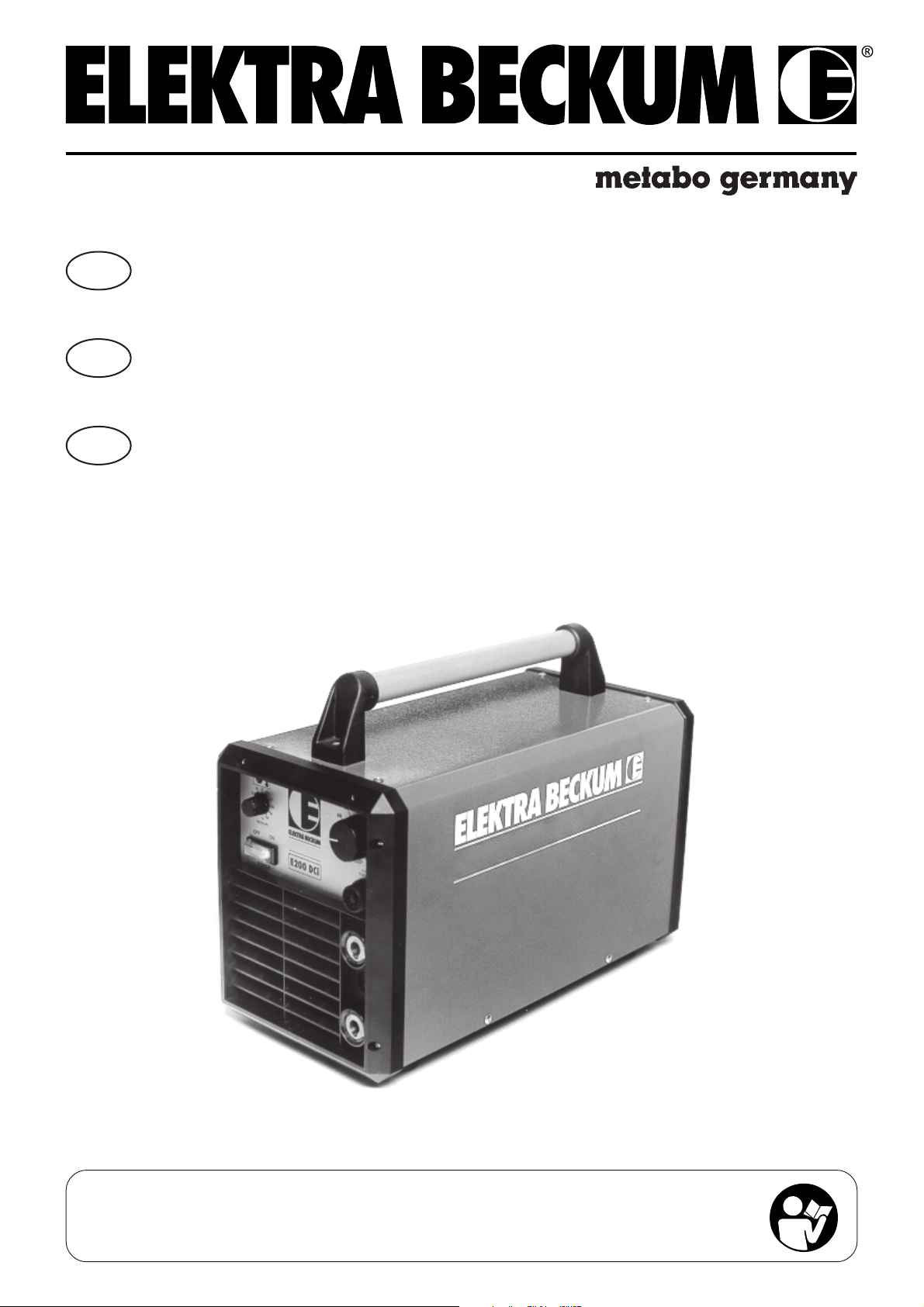
E 200 DCi
Achtung! Lesen Sie diese Anleitung vor der Installation und Inbetriebnahme aufmerksam durch.
Important! Carefully read through these instructions prior to installation and commissioning.
¡Atención! Lea con detenimiento estas instrucciones antes de la instalación y de la puesta en servicio.
115 115 9717 / 0603 - 1.3
Page 2

Inhaltsverzeichnis
D
1 Technische Daten
2 Anwendungsbereich
2.3 Leistungsschild
3 Inbetriebnahme
4 Funktionsbeschreibung
5 Anwendung
6 WIG-Schweißbetrieb
6.1 Gebrauchshinweise WIG
1 Technische Daten
Netzspannung: 3 ~ 400 V
Netzfrequenz: 50 - 60 Hz
Leerlaufspannung: 90 V
Stromeinstellbereich: 5 - 200 A DC/Elektrode
Eingangsleistung:
Elektrode 8,0 kVA
WIG 5,3 kVA
Arbeitsspannung:
Elektrode 28 V
WIG 18 V
Netzsicherung: T 16 A
Einschaltdauer:
WIG 200 A - 100 %
Elektrode 200 A - 80 %
Betriebsarten: Elektrode/WIG
Arbeitsbereiche: Elektrode ab 1,0 mm
WIG für Stahl ab 0,3 mm
Leistungsfaktor cos ϕ: 0,95
Schutzart: IP 23
Kühlart: F
Isolierstoff-Klasse: F
Temperaturbereich: Betrieb -10°C - +40°C
Lagerung -25°C - +70°C
Maße: 500x245x285 mm
Gewicht: 19,5 kg
Verschweißbarer Elektroden Ø: 5 mm
7 Überlastung
8 Störungsbeseitigung
9 Gefahrenhinweise
9.1 Schutz gegen elektrische Unfälle
10 Symbole
11 Schaltplan
2 Anwendungsbereich
Das E 200 DCi-Gerät ist als praxisgerechtes, baustellensicheres Gerät konzipiert. Mit ihm lassen sich alle Metalle
(außer Alu im WIG Betrieb) verschweißen. Besonderen Wert wurde auf das Lichtbogenverhalten im Elektrodenschweißbetrieb gelegt. Durch den idealen Strombereich ist das Gerät universell einsetzbar, z.B. im Rohrleitungsbau: Wurzelnähte im WIG-Betrieb, Füll- und Decknähte im Elektroden-Betrieb, schweißen von Fallnähten mit
Celelose-Elektoden.
Produkthaftung/Garantie
Nicht aufgeführte Arbeiten und Einsatzmöglichkeiten bedürfen der schriftlichen Genehmigung der Firma Metabo
GmbH, Business Unit Elektra Beckum, Postfach 1352, D-49703 Meppen.
Den Kaufbeleg bitte aufbewahren! Ein Anspruch auf Garantieleistungen besteht nur gegen Vorlage des Kaufbelegs. Die Adresse Ihrer nächstgelegenen Werkvertretung finden Sie auf der hinteren Umschlagseite.
Bitte melden Sie sich mit Garantieansprüchen bei Ihrem Fachhändler.
Garantiearbeiten werden grundsätzlich durch uns oder von uns autorisierten Servicestellen durchgeführt.
Außerhalb der Garantiezeit dürfen Reparaturen nur durch autorisierte Servicestellen durchgeführt werden.
Bitte Reparaturrechnungen verwahren!
Technische Änderungen vorbehalten!
Page 3
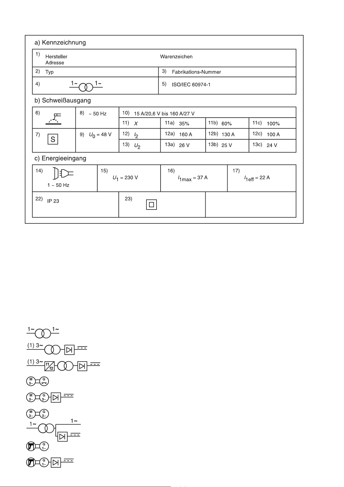
2.3 Leistungsschild - Kennwerte für den Netzanschluß
Die folgenden Angaben beziehen sich auf die benummerten Felder in 2.3 entsprechend ISO/IEC 60974-1
a) Kennzeichnung:
Feld 1 Name und Adresse des Herstellers, des Vertreibers oder Importeurs und wahlweise ein Warenzeichen
und das Ursprungsland, falls erforderlich.
Feld 2 Typ (Bezeichnung) nach Herstellerangabe.
Feld 3 Nachweis für Konstruktions- und Herstellungsdaten (z. B. Fabrikationsnummer).
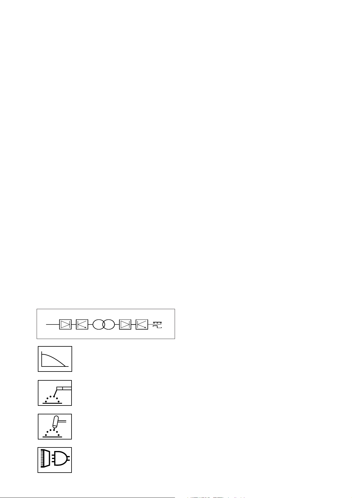
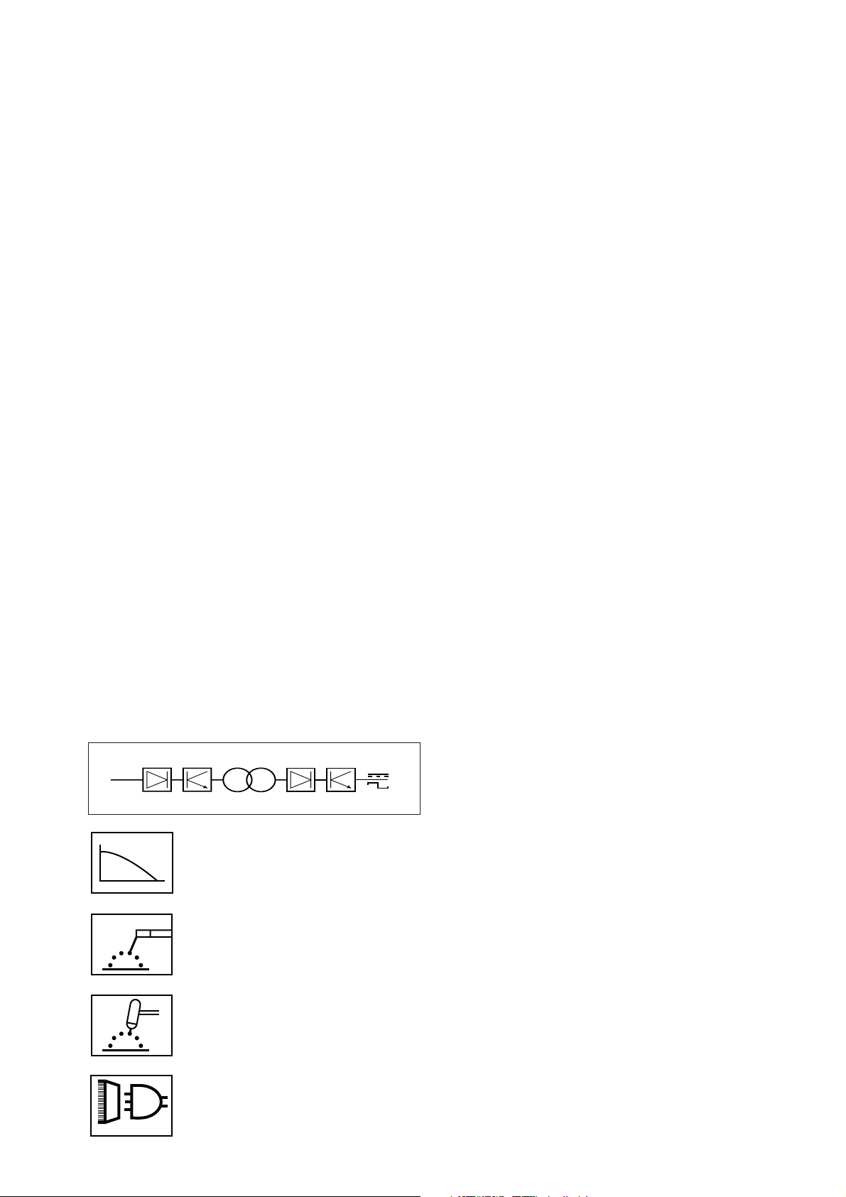
Feld 4 Bildzeichen für die Schweißstromquelle (wahlweise), z. B.:
Einphasiger Transformator
Ein-/ Dreiphasiger Transformator mit Gleichrichter
Ein Dreiphasiger statischer Frequenzumformer-Transformator-Gleichrichter
Dreiphasiger Gleichstrom-Umformer
Dreiphasiger Umformer mit Gleichrichter
Dreiphasiger umlaufender Frequenzumformer
Einphasige kombinierte Stromquelle für Wechsel- und Gleichstrom
Wechselstrom-Generator mit Verbrennungsmotor
Wechselstrom-Generator mit Verbrennungsmotor und Gleichrichter
Page 4

Feld 5 Hinweis auf diese Norm, als Bestätigung, dass die Schweißstromquelle ihren Anforderungen entspricht.
b) Schweißausgang:
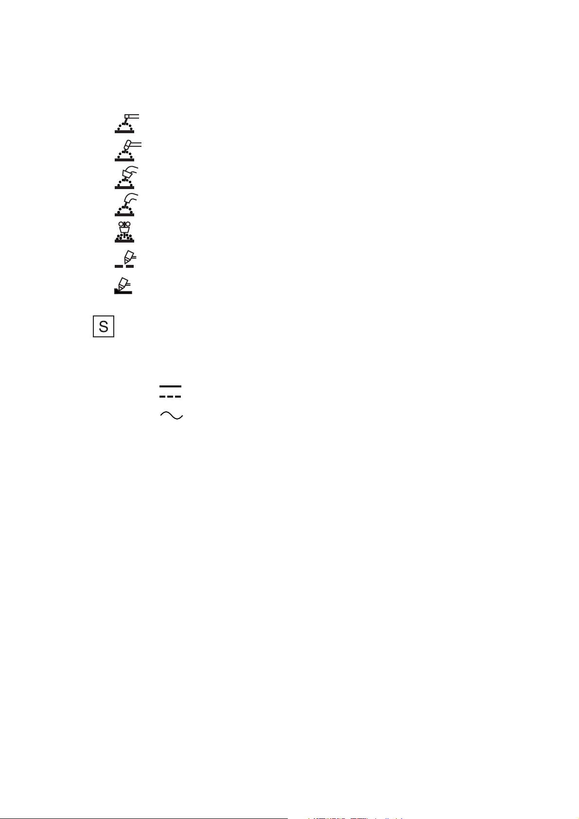
Feld 6 Bildzeichen für das Schweißverfahren, z. B.
Lichtbogenhandschweißen mit umhüllten Stabelektroden
Wolfram-lnerrtgas-Schweißen
Metall-Inert- und -Aktivgas-Schweißen einschließlich der
Verwendung von Fulldraht
Selbstschützendes Fulldrahtschweißen
Unterpulver-Schweißen
Plasmaschneiden
Plasmafugenhobeln
Feld 7 Symbol für Schweißstromquellen, die zum Schweißen m Umgebung mit erhöhter elektrischer
Gefährdung geeignet sind (falls zutreffend)
Feld 8 Symbol für den Schweißstrom, z B
Gleichstrom
Wechselstrom und zusätzlich der Bemessungswert der Frequenz in Hz, z. B.: ~50 Hz
Feld 9 U0 .......V Leerlaufspannungs-Bemessungswert
a) Arithmetischer Mittelwert bei Gleichspannung;
b) Effektivwert bei Wechselspannung:
Feld 10 .....A/.....V bis...A/...V Leistungsbereich, kleinster und größter Bemessungswert des Schweißstrom
und entsprechende genormte Arbeitsspannung.
Feld 11 X Symbol für die Einschaltdauer
Feld 12 I2 Symbol für den Bemessungswert des Schweißstroms
Feld 13 U2 Symbol für die genormte Arbeitsspannung.
Felder 11 a, 11b, 11c...% Wert der Einschaltdauer.
12a, 12b, 12c...A Wert des Bemessungswerts des Schweißstroms.
13a, 13b, 13c...V Wert der genormten Arbeitsspannung.
Diese Felder bilden eine Tabelle mit entsprechenden Werten für die drei Einstellungen:
a) ...% Einschaltdauer beim größten Bemessungswert des Schweißstroms,
b) 60 % Einschaltdauer;
und
c) 100 % Einschaltdauer (soweit zutreffend).
Page 5

Spalte a) braucht nicht ausgefüllt zu werden, wenn die Einschaltdauer beim größten Bemessungswert des
Schweißstroms 60 % oder 100 % beträgt
Spalte b) braucht nicht ausgefüllt zu werden, wenn die Einschaltdauer beim größten Bemessungswert des
Schweißstroms 100 % beträgt
c) Energieeingang:
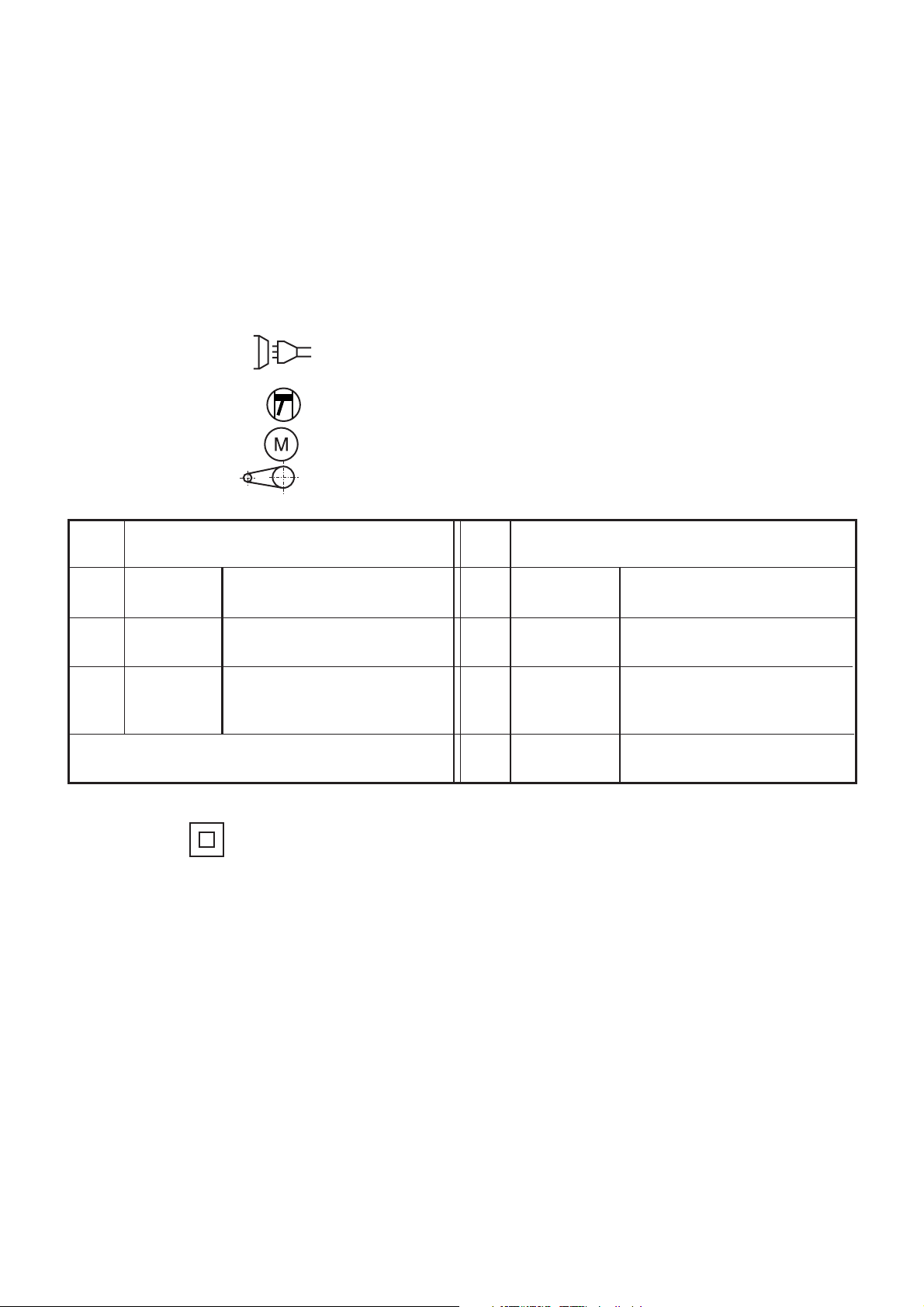
Feld 14 Bildzeichen für den Energieeingang, z B
Netzeingang, Anzahl der Phasen ( z. B. 1 oder 3), Bildzeichen für Wechselstrom und den
Bemessungswert der Frequenz (z. B. 50 Hz oder 60 Hz)
Verbrennungsmotor
Elektromotor
Riementrieb
Feld
15
Elektrisch betriebene Schweißstromquelle Feld
... V
U
1
Bemessungswert der
18
Netzspannung
16
I
1max
Größter Bemessungswert
19
... A
des Netzstroms
... A
17
I
1eff
Effektivwert des größten
20
Netzstroms
Die Felder 15 bis 17 bilden eine Tabelle mit sich
21
entsprechenden Werten.
Feld 22 IP.. Schutzart, z B IP 21 oder IP 23
Feld 23 Symbol für Schutzklasse II (falls zutreffend)
n
... min
... min
n
0
... min
n
i
P
1max
Mechanisch angetriebene
Schweißstromquelle
-1
Bemessungswert der
Lastdrehzahl
-1
Bemessungswert der
Leerlaufdrehzahl
-1
Bemessungswert der
abgesenkten Leerlaufdrehzahl
(falls zutreffend)
... kW
Höchste Leistungsaufnahme
(falls zutreffend)
Page 6
3 Inbetriebnahme
Achtung!
Die Geräte werden im Werk mit großer Sorgfalt gebaut und eingehend geprüft. Alle Geräte durchlaufen eine
computergesteuerte Prüfeinrichtung. Bitte überprüfen Sie die Maschine unverzüglich nach dem Auspacken auf
eventuelle Transportschäden. Im Falle eines Defektes informieren Sie bitte unverzüglich Ihren Lieferanten. Achten
Sie bitte beim Anschluß des Gerätes unbedingt auf die richtige Anschlußspannung (entsprechend dem Typenschild). Der Anschluß erfolgt an das Wechselstromnetz 3~400 V. Der Stromkreis, an dem die Anschlußsteckdose
liegt, ist mit einer trägen Sicherung T 16 A abzusichern. Der Betrieb weiterer elektrischer Geräte am gleichen
Stromkreis ist während des Schweißens nur begrenzt möglich.
Als Schutzgas im WIG-Schweißbetrieb wird vornehmlich reines Argon (Reinheit min. 99,998 %) verwendet. Der
Gasanschluß darf nur über eine geeignete Druckmindereinrichtung (max. 10 bar) erfolgen. Die Massezange muß
mit einem Anschlußkabel mit mindestens 35 mm2 ausgerüstet sein. Nach der Betätigung des Hauptschalters (1)
ist das Gerät betriebsbereit.
4 Funktionsbeschreibung
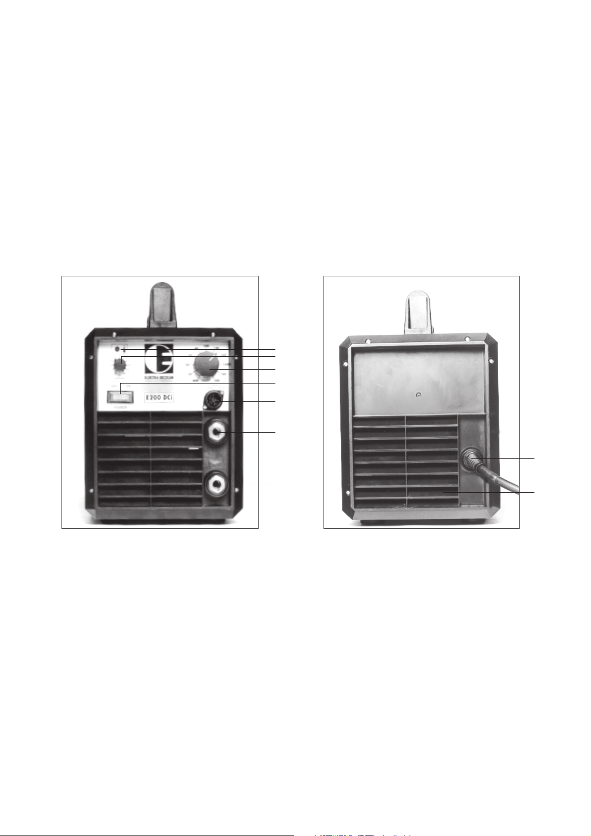
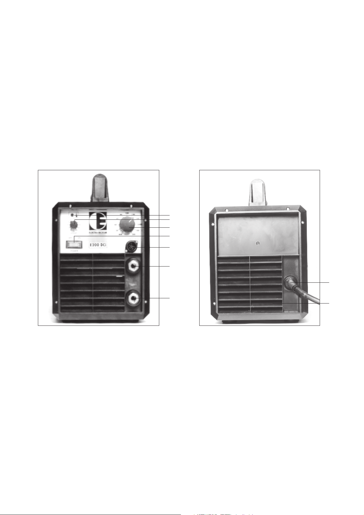
Bedienungselemente (siehe Abbildung)
4
3
2
1
5
6
7
Bild: 1 Vorderansicht
Bild 2: Hinteransicht
1 - Hauptschalter EIN/AUS
2 - Schweißstromeinstellung 5 - 200 A
3 - Potentiometer Hotstart für Elektroden- und WIG-Schweißen (Stromaddition 0 - 100 %)
4 - Kontrollampe Angabe der Übertremperatur oder des Kurzschlußes
5 - Anschluß Fußregler
6 - Anschluß - Pol, Elektrode, WIG-Betrieb-Brenneranschluß
7 - Anschluß + Pol, Elektrode, WIG-Betrieb-Massezange
8 - Anschluß Netzkabel
9 - Lüfter
8
9
5 Anwendung
Das Schweißgerät E 200 DCi ist ein primär getakteter Vollinverter der geeignet ist für das Verschweißen von
Stabelektroden und das WIG-Schweißen DC (Gleichstrom).
Die Durchmesser der Elektroden und folglich der für das Schweißen erforderliche Strom werden entsprechend der
zu schweißenden Teile festgelegt.
Page 7

Staub, Schmutz oder Eisenspäne schaden jedem Schweißgerät. Insbesondere sollten Sie darauf achten, daß zur
Kühlung die Luftzufuhr intakt bleibt.
Vor Beginn der Schweißung müssen die Schweißstellen von Schmutz, Rost, Fett und Farbresten gesäubert
werden. Ebenso muß Schlacke von den vorhergehenden Schweißungen immer erst entfernt werden.
Nun wird die Massezwinge fest an einer blanken Stelle des Werkstückes befestigt. Prüfen Sie ob alle Kabelanschlüsse und die Kabel selbst in Ordnung sind, um einen bestmöglichen Stromfluß gewährleisten zu können.
In die dafür vorgesehene Kerbe des Elektrodenhalters wird die Elektrode mit dem umhüllungsfreien Ende
eingespannt. Mit dem Gerät kann eine Schweißausrüstung mit einem Schweißschild und einem Schlackehammer
erworben werden. Das Schutzglas dient als Filter gegen schädliche Strahlungen (Ultraviolette- und Infrarote
Strahlen). Das Klarglas soll das Schutzglas vor Schweißspritzern und Beschädigungen schützen. Beim Entfernen
der Schlacke sollten Sie zum Schutz der Augen gegen scharfe und heiße Schlackespritzer unbedingt eine
Schutzbrille tragen. Je nach Elektrodenart und Augenempfindlichkeit werden Schutzgläser in unterschiedlichen
Helligkeitsstufen angeboten.
Für den Normalfall verwendet man für Elektroden mit einem Ø von 1,5 bis 5 mm Schutzgläser der Stufe DIN 9.
Damit Sie den für die von Ihnen verwendete Elektrode richtigen Strom einstellen, dient Ihnen die untere
Tabelle (1):
Ampere(A) Elektroden-Ø Materialdicke
in mm in mm
25 - 50 1,0 - 2,0 1,0 - 2,0
50 - 100 2,0 - 2,5 2,0 - 4,0
100 - 130 2,5 - 3,25 4,0 - 8,0
140 - 200 3,25 - 5,0 8,0 - 12,0
Grundsätzlich sollte niemals eine zu dicke Elektrode benutzt werden.
Als Richtwert kann man rechnen, pro mm Elektrode-Kerndraht-Ø ca. 40 Ampere Stromstärke. Je nach
Elektroden-, Werkstückdicke und Schweißnahtlage kann man den errechneten Wert über- oder unterschreiten.
Die Geräte arbeiten auch im Dünnblechbereich. Jeder Praktiker wird diese Eigenschaft begrüßen. Die Handlichkeit
bei gleichzeitig robuster Bauweise ist der große Vorteil.
Sehr gute Schweißeigenschaften hat das Gerät beim Schweißen von Fallnähten mit Celelose-Elektroden. Ein
ruhiger, stabiler Lichtbogen sorgt für saubere Verschweißung bei der fallenden Position. Begrüßt wird diese
Eigenschaft insbesondere bei der Rohrschweißung.
Ein kleiner Überblick über Schweißelektroden und ihre richtige Handhabung
Damit eine sichere Schweißung möglich ist, müssen Elektroden immer trocken gelagert werden. Sollten
Elektroden einmal feucht geworden sein, müssen sie in einem Ofen bei 200 bis 300°C etwa 1 - 2 Stunden lang
rückgetrocknet werden.
Basische Elektroden grundsätzlich vor Gebrauch im Ofen bei 200 bis 300°C bis zu 3 Stunden rücktrocknen, sofern
die Elektroden nicht Vakuum verpackt sind.
Die Kennzeichnung von Schweißelektroden ist in der EN 499 genormt.
Die Bezeichnung wird von Elektrodenherstellern nach der Norm festgelegt und von einer Überwachungsstelle
überprüft. Auf dem Elektrodenpaket ist die Bezeichnung aufgedruckt.
Page 8
Hinweise über das Schweißen selbst
Wegen der großen Unterschiede und der Vielseitigkeit der für das Schweißen wichtigen Punkte bei den verschiedenen
Elektrodentypen, soll hier nur über die gebräuchlichen Elektroden für normale Baustähle, die Rutil- bzw. Rutil/ZelluloseElektrode, gesprochen
werden. Sollten Sie einmal andere Elektroden verschweißen, so können Sie von den Elektroden-Herstellern Hinweisblätter für die Verarbeitung der speziellen Elektroden erhalten.
Die ersten Schweißungen sollten Sie auf einem Probeblech ausführen. Den zu diesem Blech gehörenden ElektrodenØ und die richtige Stromstärke wählen Sie nach Tabelle 1. Das Anlegen der Massezwinge und das Einspannen der
Elektrode führen Sie durch wie zu Anfang beschrieben. Nun halten Sie die Elektrode ca. 2 cm über den Anfangspunkt
Ihrer Schweißnaht und nehmen dann das Schweißschild vors Gesicht. Die Elektrode kurz auf das Blech anstreichen.
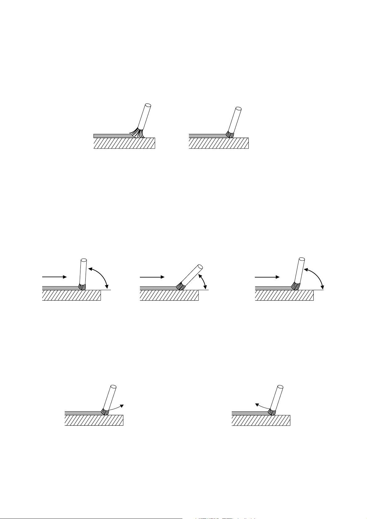
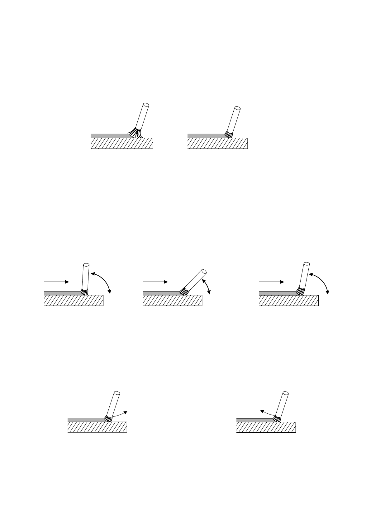
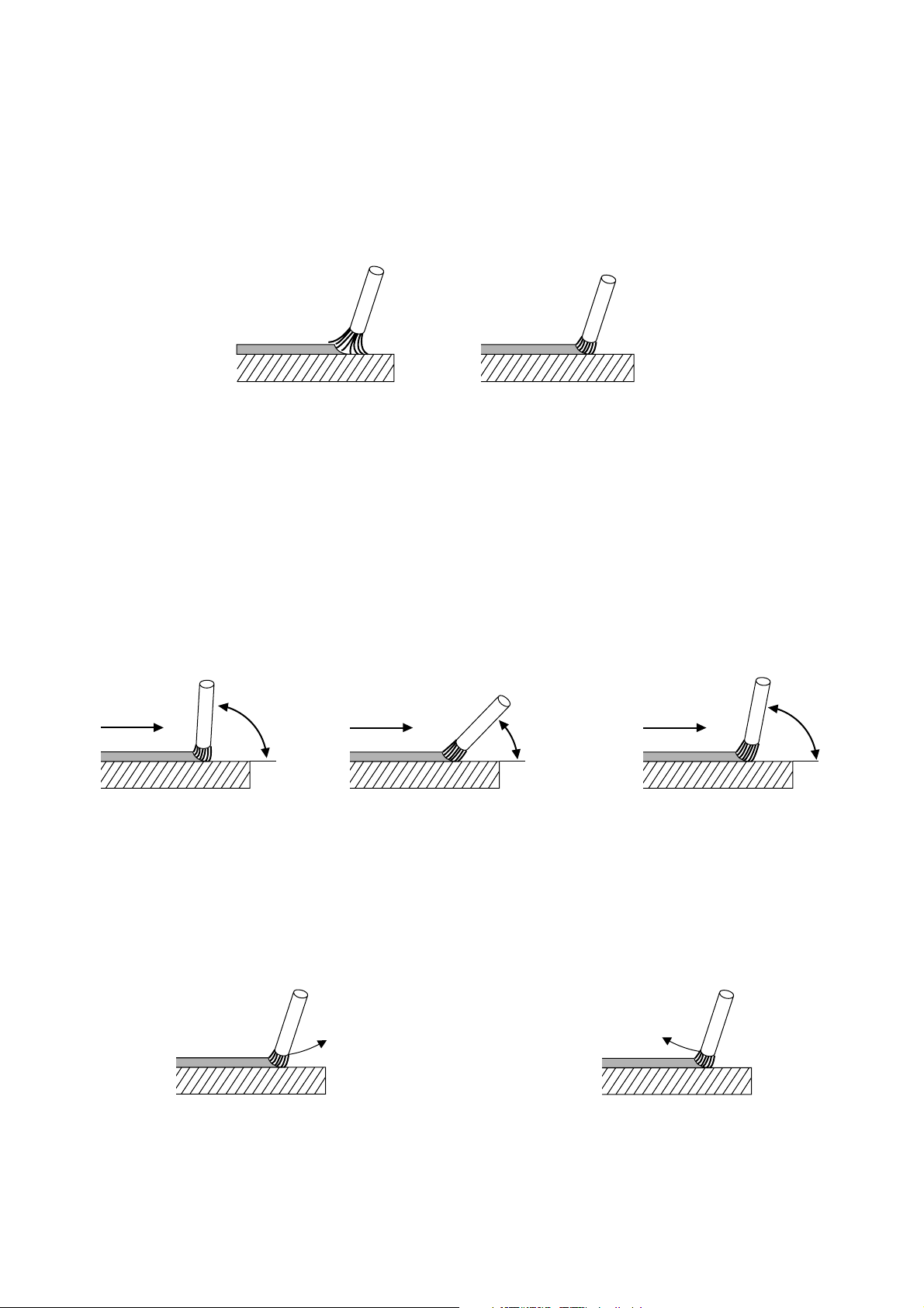
Durch das Schutzglas des Schutzschildes beachten Sie den Lichtbogen.und halten ihn auf eine Länge von 1- bis 1,5fachen Elektroden-Ø.
falsch
Lichtbogen zu lang
(Bild 3)
richtig
ca. 1-1,5 mal Elektroden-Ø
(Bild 4)
Die richtige Lichtbogenlänge ist wichtig, weil sich bei zu kurzem oder zu langem Lichtbogen der Strom und die Spannung
verändern. Bei zu niedriger Schweißspannung ist der Einbrand zu gering. Zu hoher oder zu niedriger Schweißstrom
haben eine schlechte Schweißnaht zur Folge. Ein zu langer Lichtbogen schmilzt den Grundwerkstoff nicht genügend
auf, es gibt hohe Spritzverluste und die Atmosphäre kann mit ihren schädlichen Stoffen wie Wasserstoff und Stickstoff
an das Schmelzbad heran.
Für eine gute Schweißnaht ist auch der Ausstellwinkel der Elektrode zum Werkstück von wesentlicher Bedeutung. Der
Winkel sollte etwa 70 bis 80° zur normalen Schweißrichtung betragen. Bei einem zu steilen Anstellwinkel läuft die
Schlacke unter das Schmelzbad und bei einem zu flachen flattert und spritzt der Lichtbogen, was in beiden Fällen zu
einer porösen schwachen Schweißnaht führt (siehe Bild 5 bis 7).
falsch
Schweißrichtung
> 80°
falsch richtig
Schweißrichtung
Schweißrichtung
< 70°
70-80°
(Bild 5)
(Bild 6)
(Bild 7)
Der Schweißer muß darauf achten, daß der Lichtbogen immer gleich lang bleibt, daß heißt, daß der Abbrand durch den
Lichtbogen ständig durch Nachführen der Elektrode ausgeglichen wird.
Gleichzeitig muß das Schweißbad auf gleichmäßigen Einbrand und Breite beobachtet werden.
Geschweißt wird immer von links nach rechts (ziehend).
Geht die Schweißnaht dem Ende zu, so darf die Elektrode nicht einfach nach oben oder nach vorn weggezogen werden,
dadurch entstehen ungewollte poröse Endkrater, die die Naht schwächen würden. Richtig ist es, am Ende der Naht
einen kurzen Augenblick zu halten, um dann durch einen Bogen über die Naht abzuheben.
falsch
(Bild 8)
richtig
(Bild 9)
Die Schlacke darf erst von der Naht entfernt werden, wenn sie soweit abgekühlt ist, daß sie nicht mehr glüht.
Soll die Schweißung an einer unterbrochenen Schweißnaht fortgesetzt werden, so muß zuerst die Schlacke an der
Ansatzstelle entfernt werden. Dann wird der Lichtbogen in der Nahtfuge oder der schon vorhandenen Naht wie vor
beschrieben, gezündet und zur Anschlußstelle geführt, wo der Absatz richtig aufgeschmolzen werden muß und dann
kann weitergeschweißt werden wie beschrieben.
Page 9

6 WIG-Schweißbetrieb
Bei dem Schweißgerät E 200 DCi ist durch den gleichen Kennlinienverlauf wie beim Elektrodenschweißen ein
WIG-Schweißen möglich.
Verwendet wird ein WIG-Brenner SR 26 V der immer an der - Polung (7) angeschlossen wird. Die Zündung des
Lichtbogens erfolgt über das Anstreichen der Wolframelektrode am Material (Erzeugung eines Kurzschlußes).
Auch beim WIG-Schweißen wird angeraten, am Inverter einen bestimmten Stromstoß (Hotstart) einzustellen, um
die Zündung des Lichtbogens während des Anstreichen zu erleichtern.
Die Gaszufuhr erfolgt über ein Direktanschluß vom Brenner an den Druckminderer der Gasflasche. Empfohlen wird
eine Einstellung der Durchflußmenge von 6 - 7 l/min.
Die Verbindung zum Schweißtisch bzw. Werkstück erfolgt mit dem Anschluß (6). Der Lichtbogenstrom wird mit
Hilfe des Poteniometers (2) vorgewählt. Die Zündung des Lichtbogens erfolgt dann durch kurzzeitigen Kontakt der
Wolfram-Elektrode zum Werkstück.
6.1 Gebrauchshinweise WIG
Um ein sicheres Zünden und einwandfreie Schweißergebnisse zu erzielen, sollten folgende Punkte beachtet
werden:
Elektrodentyp
1
Es sollten nur thorierte Elektroden verwendet werden
z.B. WT 20 1,8 - 2,2 % Thorium, Kennfarbe: rot
Elektrodendurchmesser
2
Der Elektrodendurchmesser muß dem Lichtbogenstrom angepaßt sein.
Richtwerte: unter 80 A: Durchmesser 1,0 mm
70 bis 140 A: Druchmesser 1,6 mm
130 bis 200 A: Durchmesser 2,4 mm
Das Anschleifen der Elektroden darf nur in Längsrichtung erfolgen!
3
Eine zu hohe Gasmenge kann die Zündeigenschaften verschlechtern.
4
7 Überlastung
Das Schweißgerät E 200 DCi ist durch Schutzeinrichtungen sicher gegen Überlastung geschützt. Beim Überschreiten der zulässigen Einschaltdauer erfolgt automatisch eine Abschaltung des Gerätes. Dieses wird durch die
Kontrollampe (4) angezeigt.
Nach kurzer Zeit ist das Gerät wieder betriebsbereit.
Achtung: Das Gerät in der Kühlphase nicht ausschalten, da sich sonst die Kühlzeit erheblich verlängert (Ventilator
steht).
8 Störungsbeseitigung
Während des Schweißens leuchtet die Kontrollampe (4) und das Gerät liefert keinen Strom mehr.
Während des Schweißens hat man Schwierigkeiten, die Zündung des Lichtbogens aufrecht zu erhalten.
Wenn das Gerät eingeschaltet ist und kein Schweißstrom anliegt.
Schutzvorrichtung bei Übertemperatur ist ausgelöst.
Gerät einige Minuten bei Stromversorgung laufen
lassen.
Falls die Elektroden nicht überlagert, feucht oder beschädigt sind, besteht die Möglichkeit, daß die Stromversorgung zu niedrig ist oder die Zuleitung zu lang ist.
- Sicherung überprüfen
- Stromspannung zu hoch da dann die entsprechende
Schutzvorrichtung einsetzt.
Gerät zündet beim WIG-Schweißen schlecht.
Poren in den Schweißnähten.
- kein Gas oder nicht genügend Gas
- Wolframelektrode falsch angeschliffen
- falscher Elektrodendurchmesser
- Materialoberfläche ist nicht fettfrei
- falsche Einstellung der Durchflußmenge (zu hoch,
oder zu niedrig)
- falsches Gas (nur Reinargon)
- verunreinigtes Gas
Page 10
9 Gefahrenhinweise
- Das Gerät darf nur für den vorgesehenen Anwendungsbereich eingesetzt werden (WIG- und Elektrodenschweißen).
- Das Gerät nur in trockener Umgebung einsetzen (Schutzart IP 23)).
- Nur an Stromquellen mit einwandfrei funktionierender Schutzmaßnahme betreiben.
Beim Lichtbogenschweißen ist die Unfallvorhütungsvorschift 21.0 "Schweißen, Schneiden und verwandte
Arbeitsverfahren" (VGB 15) zu beachten.
9.1 Schutz gegen elektrische Unfälle
Die Schweißleitungen sind gut leitend und mechanisch fest anzuschließen. Netz- und Schweißleitungen sind
gegen Beschädigungen zu schützen. Eventuell beschädigte Anschlußleitungen sind gegen Originalteile auszuwechseln. Bei kurzen Schweißpausen ist der Brenner auf einer isolierenden Unterlage abzulegen. Bei längeren
Arbeitsunterbrechungen ist das Schweißgerät abzuschalten. Beim Schweißen sollen trockene und isolierende
Handschuhe und Schuhe getragen werden. Bei Wartungs- und Reparaturarbeiten ist das Gerät vom Netz zu
trennen. (Netzstecker ziehen).
Schutzmaßnahmen gegen Strahlen, Verbrennungen und Vergiftungen:
- Durch Tragen geeigneter Schutzkleidung (Stulpenhandschuhe, Schweißerschürze etc.) werden Verbrennungen vermieden.
- Beim Schweißen ist immer ein Schutzschild zu benutzen.
- Der Arbeitsplatz ist so abzuschirmen, daß in der Nähe befindliche Personen geschützt sind.
- Beim Schweißen von verunreinigten Oberflächen können giftige Gase entstehen. Sorgen Sie für eine saubere
Oberfläche.
- Verzinkte Teile dürfen nicht verschweißt werden, da Zinkdämpfe giftig sind.
- Beim Arbeiten in engen Räumen ist für ausreichende Be- und Entlüftung zu sorgen.
- Beim Schweißarbeiten unter erhöhter elektrischer Gefährdung muß eine unbeschädigte, trockene und isolierende Schutzkleidung getragen werden.
Brandvorsorge
- Glühende Metallperlen oder Funken können bei Kontakt mit entflammbaren festen, flüssigen oder gasförmigen
Stoffen Feuer auslösen.
- Samtliches entzündliche- und entflammbare Material aus dem Arbeitsbereich entfernen.
- Behälter zur Aufbewahrung von Kraftstoff, Schmier- und Lösemitteln sollten nicht geschweißt werden, auch
nicht, wenn sie leer sind. Dies gilt ebenso für Hohlräume, welche entzündliche Materialen enthalten oder
enthalten haben.
10 Symbole
3~
Spannungskennlinie
Elektrodenschweißen
3~
WIG-Schweißen
Netzanschluß über Stecker,
2-phasig + Schutzleiter
Page 11
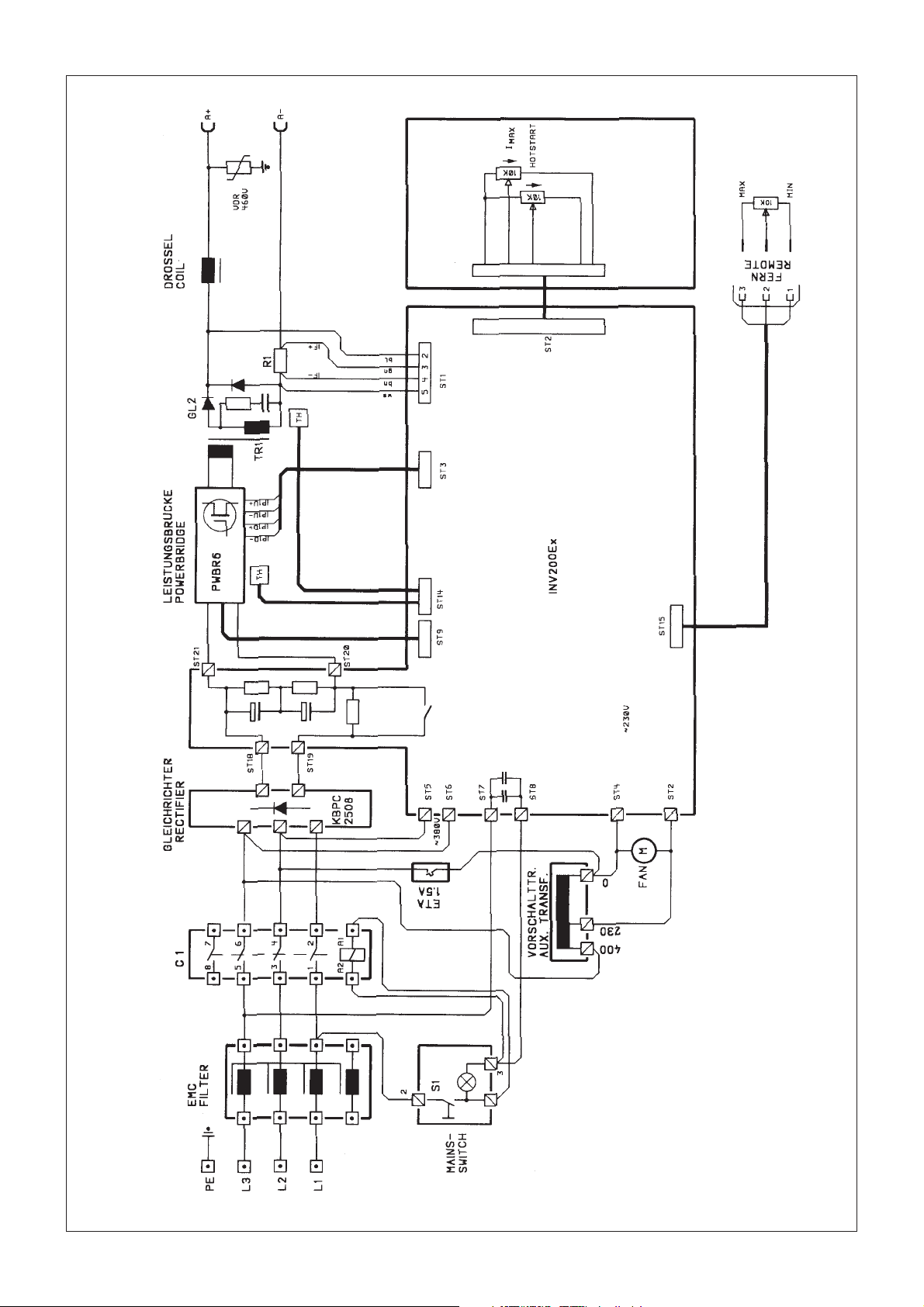
11 Schaltplan
Page 12

Contens
ENG
1 Specifications
2 Scope of Application
2.3 Shown On Type Plate
3 Initiation
4 Controls
5 Manual Arc Welding
6 TIG Welding
6.1 Practical Hints For Operation
7 Overloads
8 Trouble Shooting
9 Safety Precautions
9.1 Protection Against Electrical Shock
10 Symbols
11 Wiring Diagram
1 Specifications
Power Mains: 3 ~ 400 V
Mains Frequency: 50 - 60 Hz
Open Circuit Voltage: 90 V
Welding Current Range: 5 - 200 A DC/stick electrode
Power Input:
Electrodes 8.0 kVA
TIG 5.3 kVA
Working Voltage:
Electrodes 28 V
TIG 18 V
Mains Fuse: 16 A time-lag
Duty Cycle:
TIG 200 A - 100 %
Electrodes 200 A - 80 %
Welding Modes: Manual Arc/TIG
Working Range: Electrodes from 1,0 mm
TIG for steel from 0.3 mm
Power Factor cos ϕ: 0.95
Protection Class: IP 23
Cooling: F
Insulation Class: F
Temparature Range: Operation -10°C to +40°C
Storage -2°C5 to +70°C
Dimensions: 500x245x285 mm
Weight: 19.5 kg
Verschweißbarer Elektroden Ø: 5 mm
2 Scope Of Application
This welding machine model E 200 DCi is designed as a ultra-compact, suitable for on-site work inverter welding
machine. It will weld all metals except aluminium. Special consideration was given to the arc behaviour for manual
arc welding. Due to its ideal current range this machine is very versatile in use, e.g. for pipeline construction: root
runs in TIG mode, filler welds and cover passes with manual arc welding.
Product Liability/Warranty
This product shall only be used as specified. Any other use requires the written consent of
Metabo GmbH, Business Unit Elektra Beckum, P.O.Box 1352, D-49703 Meppen, Germany.
Please contact your dealer for any warranty claims.
Warranty work will essentially be carried out by service centres authorised by us. Repairs beyond the warranty
period may be carried out only by our authorised service centres.
Please preserve all repair invoices!
We reserve the right to make technical changes!
Page 13

2.3 Information - Shown On Type Plate
The following explanations refer to the numbered boxes shown in Figure 2.3 according to ISO/IEC 60974-1.
a) Identification
Box l Name and address of the manufacturer or distributor or importer and, optionally, a trade mark and the
country of origin, if required
Box 2 Type (identification) as given by the manufacturer
Box 3 Traceability of design and manufacturing data, e.g. serial number
Box 4 Welding power source symbol (optional) e g
Single-phase transformer
Single- or three-phase transformer-rectifier
Single- or three-phase static frequency
converter-transformer-rectifier
Three-phase motor-generator
Three-phase motor-generator-rectifier
Three-phase rotating frequency Converter
Single-phase combined a.c. and d.c. power source
Engine-a.c. generator
Engine-generator-rectifier
Box 5 Reference to this Standard confirming that the welding power source complies with its requirements
Page 14

b) Welding Output
Box 6 Welding process Symbol e.g.:
Manual metal arc welding with
covered electrodes
Tungsten inert-gas welding
Metal inert and active gas welding
including the use of flux cored wire
Selfshielded flux cored arc welding
Submerged arc welding
Symbol for plasma cutting
Symbol for plasma gouging
Box 7 Symbol for welding power sources which are suitable for supplying power to welding operations
carried out in an environment with increased hazard of electric shock (if applicable).
Box 8 Welding current symbol e.g.:
Direct current
Alternating current, and additionally the rated frequency in
hertz e.g.: ~50 Hz
Box 9 U0... V Rated no-load voltage
a) Arithmetic mean value in case of direct current
b) RMS value in case of alternating current
c) Ur... V Reduced rated no-load voltage in case of a voltage reducing device
d) Us... V Switched rated no-load voltage in case of an a.c. to d.c. switching device
Box 10 ... A/... V to... A/... V Range of output, rated minimum and maximum welding current and their
corresponding conventional load voltage.
Box 11 X Duty cycle (duty factor) symbol.
Box 12 I2 Rated welding current symbol.
Box 13 U2 Conventional load voltage symbol.
Boxes 11a, 11b, 11c ...% Values of the duty cycle (duty factor).
12a, 12b, 12c ... A Values of the rated welding current.
13a, 13b, 13c ... V Values of the conventional load voltage.
These boxes form a table with corresponding values of the three settings:
a) ... % duty cycle (duty factor) at the rated maximum welding current;
b) 60 % duty cycle (duty factor);
and
c) 100 % duty cycle (duty factor) as far as relevant.
Page 15

Column a) need not be used if the duty cycle (duty factor) for the rated maximum welding
current is 60 % or 100 %.
Column b) need not be used if the duty cycle (duty factor) at the rated maximum welding current is 100 %.
c) Energy input
Box 14 Energy input symbol e.g.:
Input supply, number of phases (e.g. l or 3), symbol for alternating current
and the rated frequency (e.g. 50 Hz or 60 Hz)
Engine
Motor
Belt drive
Box 22 IP.. Degree of protection, e.g. IP21 or IP23.
Box 23 Symbol for protection class II, if applicable.
Page 16

3 Initiation
Important!
This machine and its components have been inspected and tested throughout all production stages. Before being
packed for shipping each machine undergoes a final, computerized inspection. After receipt please unpack your
machine and check for any visible transport damage. If such damage is evident please notify your supplier
immediately.
When connecting to mains power be sure that the power supplied matches the rated voltage of your machine (see
machine label) and that the outlet is properly earthed/grounded. Connect to 3 ~ 400 V.
Protect circuit with a 16 A time-lag fuse. While welding do not operate other appliances or machines on this circuit.
For TIG welding pure Argon (99.996 %) should be used as shielding gas. Connect machine to gas cylinder only
by means of a suitable and approved pressure reducing and regulating device. The maximum input pressure must
not exceed 10 bar/142 psi.
The earth cable for the work piece clamp should have a minimum cross section of 35 mm2.
4 Controls
Front panel controls
Pic. 1: Front panel
1 - Mains ON/OFF
2 - Welding current selector
3 - Hotstart control (added current 0 - 100 %)
4 - Control light (Overload or short circuit)
5 - Socket for remote control
6 - Socket +, electrode holder or earth clamp (TIG)
7 - Socket -, electrode or earth clamp, TIG torch
8 - Power cable
9 - Fan
4
3
2
1
5
6
8
7
9
Pic. 2: Rear view
5 Manual Arc Welding
This welding machine E 200 DCi is a primary clocked, fully electronic inverter suitable for welding stick electrodes
and DC TIG welding.
The electrode diameter, and consequently the required welding current, are selected according to the workpiece
thickness.
Page 17

Dust, dirt and metal filings harm any welding machine. Remove any obstructions that would block the intake of the
cooling air.
Prior to welding the seams have to be prepared, any dirt, rust, grease and paint has to be removed. Also slag from
earlier weld passes must be removed.
Attach earth clamp to work piece, ensuring good conduction.
Place electrode with the uncoated end into one of the electrode holder's notches.
Select the correct welding current as shown below:
Current (A) Electrode Ø Material Thickness
15 - 50 1.0 - 2.0 mm 1.0 - 2.0 mm
50 - 100 2.0 - 2.5 mm 2.0 - 4.0 mm
100 - 130 2.5 - 3.25 mm 4.0 - 8.0 mm
140 - 200 3.25 - 5.0 mm 8.0 - 12.0 mm
In principle do not use too thick an electrode. As a general rule calculate 40 amps welding current per 1 mm of
electrode diameter. Depending on electrode type, material thickness and weld position this calculated value may
have to be adjusted to plus or minus.
Care Of Stick Electrodes And Their Correct Use
In order to achieve a good weld the electrode has to be dry, so storing in a dry place is essential. Should electrodes
have become moist, dry in an oven at 200°C to 300°C for 1 - 2 hours.
Basic-coated electrodes always require pre-drying at 200°C to 300°C for 3 hours, unless they are vacuum-packed.
Stick electrodes are coded according to EN 499 and other standards, such as B.S. 639, AWS-SFA 5.1 and ISO
2560. The codes are always shown on the electrode package. The electrode description is defined by the
manufacturer according to the standards, the description is checked by an independent test institute for
compliance. This information is shown on the packaging.
Page 18
4 Welding Hints
Because of the multitude of and great differences in the important points for welding only the very basic operations
for the most common electrodes for low-carbon steels, the rutile or rutile cellulose electrode, are introduced here. In
the case that other electrodes have to be used, the electrode manufacturers supply upon request all relevant
information for the type of special electrode to be used.
Always make some trial welds on scrap material. Select electrode diameter and welding current as per Table 1 (shown
on page 5). Attach earth clamp to work piece and place electrode into electrode holder as described earlier. Now hold
the electrode tip approx. 2 cm / 1 inch above the starting point of your welding seam. Hold the welding shield in front
of your face and draw the electrode with a short stroke along the groove. Through the welding shield you watch the
arc, keeping it to a length of 1 to 1.5 times the electrode diameter.
wrong
arc too long
(Pic. 3)
correct
approx. 1 - 1.5 the electrode-Ø
(Pic. 4)
The correct arc length is important for a good weld, because with too short or too long an arc both welding current and
working voltage change. A low working voltage causes insufficient penetration. Too high or too low welding current
gives a poor welding seam. Too long an arc does not sufficiently melt the parent material, resulting in high spatter
losses. Also the air, with its detrimental substances like hydrogen and nitrogen, may get access to the weld pool.
For a good weld the work angle of the electrode (or electrode inclination angle) is of substantial importance. The
inclination should be 70° - 80° to the welding direction. With the work angle too steep slag will run under the weld pool,
too flat an work angle causes the arc to spatter, in both cases the result is a porous, weak welding seam (see pictures
5 - 7).
wrong
welding direction
> 80°
wrong correct
welding direction
welding direction
< 70°
70-80°
(Pic. 5)
(Pic. 6)
(Pic. 7)
The welder has to keep the arc at the same length, that is the electrode burn-off is compensated by feeding the
electrode into the weld. At the same time the welder has to watch the weld pool for even penetration and width.
Welding is always done from left to right (backhand welding).
At the end of the welding seam the electrode can not simply be lifted or pulled from the weld, this creates porous end
craters, which weaken the weld. To correctly terminate a weld the electrode is held for a short moment at the end of
the weld seam, then lifted in an arc over the just laid weld.
wrong
(Pic. 8)
correct
(Pic. 9)
Remove slag only after it has cooled down and is no longer glowing.
If an interrupted weld is to be continued, the slag at the end of the already finished weld must be removed. Then the
arc can be started either in the groove or on the weld, as described earlier, and then moved to the end of the weld,
which has to be thoroughly melted for good fusion. Welding is then continued normally.
Page 19

6 TIG Welding
Since TIG welding and manual arc welding both havce the same constant current characteristics, TIG welding with
the E 200 DCi is possible.
As TIG torch a model SR 26 V is used, always connected in reverse polarity to the negative (-) pole (7). The arc
is started by bringing the tungsten electrode in contact with the work piece (touch contact ignition). As with manual
arc welding it is recommended to set the hot start to a certain boost in order to help start the arc.
Gas supply is directly from the gas cylinder's pressure regulator to the torch. A gas flow rate of approximately
6 - 7 ltr/min is recommended.
The earth clamp is connected to the positive (+) pole (6). Select the welding current with the potentiometer (2).
6.1 Practical Hints For Operation
To ensure good arc starting and good welding results the following should be adhered to:
Type of Electrodes
1
Use only thoriated electrodes, e.g.
WT 20 1.8 - 2.2 % thorium oxide, color code: red
2
Electrode Diameter
The electrode diameter should match the welding current. General values are:
less than 80 A: 1.0 mm diameter
70 to 140 A: 1.6 mm diameter
130 to 200 A: 2.4 mm diameter
Grind electrodes in longitudinal direction only!
3
To much gas flow can reduce the arc starting ability.
4
7 Overload
The welding machine E 200 DCi is positively protected against overloads. Should the durty cycle reach a critical
point the machine switches off automatically. This is indicated by the control light (4). After a short cooling-down
period the machine is operational again.
Important: Do not switch the machine off while cooling down, this cuts the power for the fan and prolongs the coolingdown period considerably.
8 Trouble Shooting
While welding the control light (4) comes on and no
welding current.
Difficulties to maintain an arc.
Overload protection activated.
Let machine cool down with power ON.
Either electrodes too old, damp or damaged or mains
voltage too low (less than 360 V under full load). Extension cord may be too long or cross section too small.
Machine switched on but not working.
Poor arc starting when TIG welding
Porous welding seams
- check mains fuse
- mains voltage higher than 440 V and machine has
switched off automatically
- too little or no shielding gas
- tungsten electrode ground wrong
- wrong electrode diameter
- work piece surface greasy
- wrong gas flow setting
- unsuitable shielding gas (pure argon only)
- gas contamination
Page 20

9 Safety Instructions
- This welding machine should only be used for its intented application (TIG welding and manual arc welding).
- Use only in dry environment (protection class IP 21).
- Operate machine only on power supply circuits having a fully operational protective bonding circuit (earth/ground
lead).
9.1 Protection Against Electrical Shock
Attach earth clamp secure and tight to the work for good conduction. Protect welding cables and mains cable from
damages. Replace damaged mains cable immediately with genuine Elektra parts. Maintain equipment well. For
short work breaks place torch or electrode holder on insulating backing. For longer work breaks switch the machine
off. Keep everything dry, including clothes, work area and equipment.
Disconnect from power before servicing!
Personal Protection
- For protection from heat, sparks, rays and electrial shock wear appropriate apparel such as welder's apron,
insulating gloves and shoes.
- When welding always use a welding visor.
- Shield work place off to protect other persons working nearby.
- Welding of material with coated surfaces may generate toxic fumes. Make sure the surface is clean.
- Do not weld galvanized or zinc-coated parts, zinc fumes are toxic.
- When working in confined spaces make sure they are well ventilated.
- When welding in areas with increased electrical hazard wear intact, dry and insulating protective clothing.
Fire Prevention
- Hot slag or sparks can cause fire when getting in contact with combustible solids, liquids or gases.
- Remove all inflammable and combustible material from the work area. Fuel, lubricant or solvent containers must
not be welded, even when they are empty. The same applies to hollow spaces containing, or having contained,
combustible materials.
10 Symbols
3~
Voltage Characteristic Curve
Manual Arc Welding
3~
TIG Welding
Mains Connection by Plug,
2-phases+ earth
Page 21
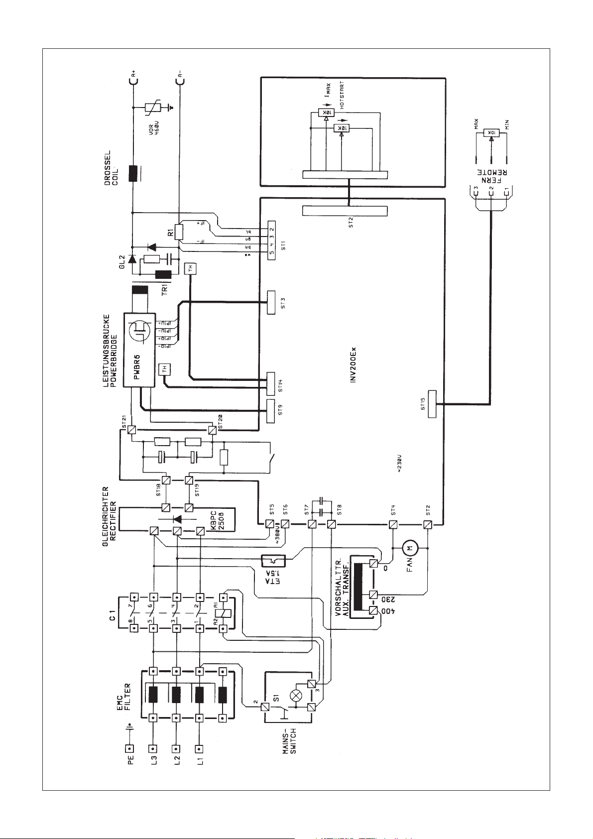
11 Wiring Diagram
Page 22

Índice
ES
1 Especificaciones técnicas
2 Campo de aplicación
2.3 Placa de características
3 Puesta en servicio
4 Descripción de funciones
5 Aplicación
6 Funcionamiento de la soldadura TIG
6.1 Indicaciones de uso TIG
7 Sobrecarga
8 Reparación de averías
9 Indicaciones de peligro
9.1 Protección contra accidentes eléctricos
10 Símbolos
11 Esquema de contactos
1 Especificaciones técnicas
Tensión de alimentación: 3 ~ 400 V
Frecuencia de red : 50 - 60 Hz
Tensión en vacío: 90 V
Margen de ajuste de corriente: 5 - 200 A CC/electrodo
Potencia de entrada:
Electrodo 8,0 kVA
TIG 5,3 kVA
Tensión de trabajo:
Electrodo 28 V
TIG 18 V
Protecciones de red: T 16 A
Duración de conexión:
TIG 200 A - 100 %
Electrodo 200 A - 80 %
Modos de funcionamiento: electrodo/TIG
Zonas de trabajo: electrodos a partir de 1,0 mm
TIG para acero a partir de 0,3 mm
Factor de potencia cos ϕ: 0,95
Modo de protección: IP 23
Clase de refrigeración: F
Clase de material aislante: F
Gama de temperatura: En servicio -10°C - +40°C
Almacenamiento -25°C - +70°C
Medidas: 500x245x285 mm
Peso : 19,5 kg
Electrodos termosoldables Ø: 5 mm
2 Campo de aplicación
La máquina E200 DCi ha sido diseñada como un aparato práctico y seguro. Con ella es posible soldar todo tipo
de metales (excepto el aluminio en funcionamiento TIG). Se ha hecho especial hincapié en el comportamiento del
arco voltaico en las tareas de soldadura con electrodo. Con el margen de corriente ideal el aparato puede aplicarse
universalmente, p. ej., en la construcción de tuberías: costuras de raíz en funcionamiento TIG, soldaduras de
relleno y de recubrimiento con funcionamiento por electrodos, soldadura de costuras verticales descendentes con
electrodos con celulosa.
Responsabilidad de producto/garantía
Los trabajos y las posibilidades de aplicación no especificados precisan una autorización escrita de la empresa
Metabo GmbH, Business Unit Elektra Beckum, apartado de correos 1352, D-49703 Meppen.
Para la defensa de sus derechos de garantía y por la seguridad del producto, asegúrese de que la tarjeta de
garantía sea rellenada de inmediato al realizar la compra y que nos sea remitida la tarjeta de respuesta.
Póngase en contacto con su proveedor en caso de derecho de garantía.
En principio, los trabajos bajo garantía serán llevados a cabo por nuestra empresa, o bien por los servicios técnicos
que autoricemos para ello. Fuera del periodo de garantía, las reparaciones sólo pueden ser realizadas por servicios
técnicos autorizados.
¡Guarde las facturas de reparación!
Reservado el derecho a modificaciones técnicas.
Page 23

2.3 Placa de características - Valores característicos para la conexión a la red
Identificación
Dirección del fabricante
Modelo
Salida de soldadura
Entrada de energía
Marca registrada
Número de fabricación
Contenido
Las indicaciones siguientes hacen referencia a los campos numerados en la imagen 2.3.
a) Identificación
Campo 1 Nombre y dirección del fabricante, del distribuidor o importador y opcionalmente una marca y el
país de origen, si es necesario.
Campo 2 Modelo (denominación) según indicación del fabricante.
Campo 3 Comprobación para datos de construcción y de fabricación (p. ej., número de fabricación).
Campo 4 Símbolo gráfico para la fuente de corriente de soldadura (opcional), p. ej.:
Transformador monofásico
Transformador monofásico/trifásico con rectificador
Rectificador transformador convertidor de frecuencias
estático monofásico/trifásico
Convertidor de corriente continua trifásico
Convertidor trifásico con rectificador
Convertidor rotativo de frecuencias trifásico
Fuente de corriente combinada trifásica para corriente
alterna y continua
Generador de corriente alterna con motor de
combustión interna
Generador de corriente alterna con motor de
combustión interna con rectificador
Page 24
Campo 5 Referencia a esta norma como confirmación de que la fuente de corriente de soldadura
satisface sus exigencias.
b) Salida de soldadura
Campo 6 Símbolos gráficos para el proceso de soldadura, p. ej.:
Soldadura manual por arco con varillas para soldar con
revestimiento
Soldadura por arco bajo gas inerte con electrodo de wolframio
Soldadura por arco bajo gas inerte y bajo gas activo incluido el uso
de electrodo con alma
Soldadura con electrodo con alma y autoprotección
Soldadura por arco sumergido
Corte con chorro de plasma
Ranurado con soplete de plasma
Campo 7 Símbolo para fuentes de corriente de soldadura que al soldar se encuentren en entornos
con elevado peligro eléctrico (si procede).
Campo 8 Símbolo para la corriente de soldadura, p. ej.:
Corriente continua
Corriente alterna y adicionalmente el valor de cálculo de la frecuencia en Hz,
p. ej.: -50 Hz.
Campo 9) U0....V Valor de cálculo de la tensión sin carga
a) Media aritmética en corriente continua
b) Valor efectivo en tensión alterna
c) UR ...V el valor de cálculo disminuido de la tensión sin carga en un dispositivo de reducción
de tensión;
d) US ...V el valor de cálculo de la tensión flotante en un dispositivo de conmutación de corriente
alterna a corriente continua.
Campo 10) ...gama de potencia, valor de cálculo menor y mayor de la corriente de soldadura y tensión de
trabajo correspondiente según la normativa
Campo 11) ...símbolo para la duración de conexión
Campo 12) ...símbolo para el valor de cálculo de la corriente de soldadura
Campo 13) ...símbolo para la tensión de trabajo normalizada
Campos 11a, 11b, 11c ...% valor de la duración de conexión
12a, 12b, 12c ...% valor del valor de cálculo de la corriente de soldadura
13a, 13b, 13c ...% valor de la tensión de trabajo normalizada
Page 25
Estos campos forman una tabla con los valores correspondientes para los tres ajustes
a) ...% duración de conexión en el valor de cálculo mayor de la corriente de soldadura:
b) 60% de duración de conexión
y
c) 100% de duración de conexión (si procede)
c) Entrada de energía:
Campo 14) Símbolos gráficos para la entrada de soldadura, p. ej.:
Entrada de red, número de fases (p. ej. 1 o 3), símbolos gráficos para la
corriente alterna y el valor de cálculo de la frecuencia (p. ej. 50 Hz o 60 Hz)
Motor de combustión interna
Motor eléctrico
Accionamiento por correa
Campo
15
16
17
Los campos 15 a 17 forman una tabla con valores
coincidentes.
Campo 22) IP... Grado de protección, p. ej., IP 21 o IP 23.
Campo 23) Símbolo para grado de protección II (si procede)
Fuentes de corriente de soldadura con
accionamiento eléctrico
U
... V
1
I
1max
I
1eff
... A
Valor de cálculo de la tensión de
alimentación
Valor de cálculo mayor de la
... A
corriente de la red
Valor efectivo de la corriente de
la red mayor
Campo
18
19
20
21 P
Fuentes de corriente de soldadura con
accionamiento mecánico
... min
... min
-1
-1
-1
... kW
n ... min
n
0
n
i
1max
Valor de cálculo de la velocidad
bajo carga
Valor de cálculo del ralentí
Valor de cálculo del ralentí bajo
(si procede)
Consumo de potencia mayor
(si procede)
Page 26
3 Puesta en servicio
¡Atención!
Los aparatos se montan en la fábrica con gran cuidado y se someten a un control exhaustivo. Todos los aparatos
pasan por una instalación de prueba controlada mediante ordenador. Asegúrese de que la máquina no ha sufrido
daños en el transporte inmediatamente después de desembalarla. En caso de algún defecto, informe de inmediato
a sus proveedores. Al conectar el aparato, asegúrese de que la tensión de conexión es la correcta (la
correspondiente a la placa indicadora). La conexión se realiza con la red de corriente alterna 3 ~ 400 V. El circuito
eléctrico en el que se encuentra el enchufe de la conexión debe asegurarse con un fusible de acción lenta de T
16 A. El funcionamiento de otros aparatos eléctricos a través del mismo circuito eléctrico durante la soldadura sólo
es posible de forma limitada.
Como gas de protección en el funcionamiento de soldadura TIG se utilizará principalmente argón puro (pureza mín.
99,998 %). El suministro de gas sólo puede realizarse a través de un dispositivo de regulación de presión adecuado
(máx. 10 bares). La pinza de masa debe ir provista de un cable de conexión de por lo menos 35 mm2. Tras el
accionamiento del interruptor principal (1) el aparato está listo para su funcionamiento.
4 Descripción de funciones
Elementos de control (véase figura)
4
3
2
1
5
6
8
Imagen 1: Vista delantera
7
Imagen 2: Vista trasera
9
1 - Interruptor general ON/OFF
2 - Ajuste de la corriente de soldadura 5 - 200 A
3 - Potenciómetro de arranque en caliente para soldadura con electrodos y soldadura TIG (adición de corriente
0 - 100 %)
4 - Indicador luminoso de la sobretemperatura o del cortocircuito
5 - Conexión regulador de pie
6 - Conexión polo -, electrodo, conexión soplete funcionamiento TIG
7 - Conexión polo +, electrodo, pinza de masa funcionamiento TIG
8 - Conexión cable de alimentación
9 - Ventilador
5 Aplicación
La máquina de soldar E 200 DCi es un inversor completo con sincronización primaria adecuada para la
termosoldadura de varillas para soldar y para la soldadura TIG CC (corriente continua).
El diámetro de los electrodos y en consecuencia, la corriente necesaria para la soldadura, se fijarán conforme a
las piezas que deban soldarse.
Page 27

El polvo, la suciedad o las virutas de hierro dañan todas las máquinas de soldar. Debería poner especial atención
en que el suministro de aire para la refrigeración permanezca intacto.
Antes de iniciar la soldadura deberá retirarse la suciedad, el óxido, la grasa y los restos de color de los puntos de
soldadura. Asimismo deberá retirarse siempre primero la escoria de soldaduras anteriores.
Luego se fija bien el tornillo de masa a una zona desnuda de la pieza de trabajo. Compruebe que todas las
conexiones de cable y los cables estén bien para poder garantizar la mejor continuidad de corriente posible.
En la entalladura del portaelectrodos prevista para este fin se sujeta el electrodo dejando el extremo sin
revestimiento. Con el aparato se puede adquirir un equipo de soldadura con escudo protector y martillo para picar
escoria. El vidrio protector sirve como filtro contra las radiaciones dañinas (rayos ultravioletas e infrarrojos). El
vidrio claro debe proteger el vidrio protector contra salpicaduras de soldadura y deterioros. Al retirar la escoria es
indispensable utilizar gafas protectoras para proteger los ojos contra las salpicaduras de escoria caliente. Se
ofrecen vidrios de protección con diferentes niveles de claridad según la clase de electrodos y la sensibilidad de
los ojos.
Normalmente, para los electrodos con un Ø de 1,5 a 5 mm se utilizan vidrios protectores del nivel DIN 9.
Para regular la corriente adecuada para el electrodo utilizado, le será de utilidad la siguiente
tabla (1):
Amperios (A) Ø electrodos Grosor del material
en mm en mm
25 - 50 1,0 - 2,0 1,0 - 2,0
50 - 100 2,0 - 2,5 2,0 - 4,0
100 - 130 2,5 - 3,25 4,0 - 8,0
140 - 200 3,25 - 5,0 8,0 - 12,0
En principio no debería emplearse nunca un electrodo demasiado grueso.
Como valor de orientación puede calcularse por cada mm de Ø de alma de electrodo unos 40 amperios de
intensidad de corriente. Según los electrodos, el grosor de la pieza de trabajo y la situación de la soldadura, es
posible sobrepasar o quedarse por debajo del valor calculado.
Los aparatos también trabajan en el ámbito de la chapa fina, lo cual es una alegría para todas las personas
prácticas. La manejabilidad simultánea en ejecuciones robustas es su gran ventaja.
El aparato posee excelentes características de soldadura para soldar costuras de relleno con electrodos de
celulosa. Un arco voltaico estable es el encargado de conseguir una soldadura limpia en la posición descendente.
Esta particularidad resulta especialmente agradecida en la soldadura de tuberías.
Un pequeño resumen sobre los electrodos de soldadura y su correcta manipulación
Para posibilitar una soldadura segura, los electrodos deben almacenarse siempre en un lugar seco. Si los
electrodos estuvieran húmedos, deben secarse de nuevo en un horno de 200 a 300 °C durante 1 - 2 horas.
Seque bien los electrodos básicos antes de su uso en el horno con 200 a 300 °C hasta 3 horas siempre y cuando
los electrodos no estén envasados al vacío.
La identificación de los electrodos de soldadura está reglamentada en la EN 499.
La denominación está fijada por los fabricantes de electrodos conforme a la normativa y se comprueba en un punto
de control. En el paquete de electrodos está impresa la denominación.
Page 28
Notas sobre la soldadura propiamente dicha
Debido a las grandes diferencias y a la versatilidad de los puntos importantes para la soldadura en los diferentes tipos
de electrodos, aquí sólo se hablará de los electrodos habituales para aceros estructurales normales, los electrodos de
rutilio o los electrodos de rutilio y celulosa
. Si alguna vez suelda con otros electrodos, podrá obtener hojas de instrucciones del fabricante de electrodos para la
manipulación de los electrodos especiales.
Deberá realizar las primeras soldaduras en una chapa de prueba. Seleccione los Ø de electrodo correspondientes a
esta chapa y la intensidad de corriente según la tabla 1. Realice la instalación del tornillo de masa y la tensión del
electrodo tal como se describe al principio. Luego mantenga el electrodo aprox. 2 cm por encima del punto de inicio
de su costura de soldadura y sitúe el escudo protector delante de la cara. Marque brevemente el electrodo sobre la
chapa. Controle el arco voltaico a través del vidrio protector del escudo protector y manténgalo a una longitud de 1 a
1,5 veces más que el Ø de electrodo.
incorrecto
arco voltaico
demasiado largo
(figura 3)
correcto
aprox. 1-1,5 x
diámetro del electrodo
(figura 4)
La longitud de electrodo adecuada es importante, pues si el arco voltaico es demasiado corto o demasiado largo, la
corriente y la tensión cambian. En caso de tensión de soldadura demasiado baja, la penetración es demasiado
reducida. Una corriente de soldadura demasiado elevada o demasiado baja tiene como consecuencia una mala costura
de soldadura. Un arco voltaico demasiado largo no refunde lo suficiente el metal base, hay una gran pérdida por
proyecciones y la atmósfera puede llegar al baño de fusión con las sustancias tóxicas, como el hidrógeno y el nitrógeno.
Para una buena costura de soldadura también es de especial importancia el ángulo de exposición del electrodo
respecto a la pieza de trabajo. El ángulo debería tener aproximadamente de 70 a 80° para conseguir una dirección de
soldadura normal. Con un ángulo de exposición demasiado pronunciado, la escoria se introduce en el baño de fusión
y con un ángulo poco pronunciado, oscila y salpica el arco voltaico, lo cual genera en ambos casos una costura de
soldadura porosa y frágil (véanse las figuras 5 a 7).
dirección
de soldadura
incorrecta
> 80°
dirección
de soldadura
incorrecta
< 70°
dirección
de soldadura
correcta
70-80°
(figura 5)
(figura 6)
(figura 7)
El soldador debe asegurarse de que el arco voltaico siempre tenga la misma longitud, lo cual significa que la erosión
eléctrica generada por el arco voltaico se equilibra continuamente siguiendo los electrodos.
Al mismo tiempo hay que vigilar que el baño de fusión tenga una penetración y una anchura constantes.
Siempre se suelda de izquierda a derecha (arrastrando).
Cuando la costura de soldadura se encuentra al final, el electrodo no debe retirarse sencillamente hacia arriba o hacia
delante, pues de este modo se generarían cráteres finales porosos indeseados que debilitarían la costura. Lo correcto
es mantenerlo un instante al final de la costura y luego levantarlo por encima de la costura con un arco.
incorrecto
(figura 8)
correcto
(figura 9)
La escoria se retirará de la costura cuando se haya enfriado tanto que ya no esté incandescente.
Si se prosigue la soldadura en una costura de soldadura interrumpida, primero hay que retirar la escoria del lugar de
empalme. Entonces se encenderá el arco voltaico en la junta de la costura o en la costura ya existente tal como se ha
descrito anteriormente y se conducirá hasta el punto de conexión donde el tramo debe refundirse correctamente y luego
puede seguirse soldando tal como se ha descrito.
Page 29

6 Funcionamiento de la soldadura TIG
Con la máquina de soldar E 200 DCi es posible realizar una soldadura TIG con el mismo trazado de curva
característica que en la soldadura por electrodos.
Se utiliza un soplete TIG SR 26 V que siempre se conecta a la polaridad - (7). El encendido del arco voltaico se
realiza marcando el electrodo de wolframio sobre el material (generación de un cortocircuito). En la soldadura TIG
también se recomienda ajustar un golpe de corriente (arranque en caliente) determinado en el inversor para facilitar
el encendido del arco voltaico durante el marcado.
El suministro de gas se realiza a través de una conexión directa del soplete al reductor de presión de la botella de
gas. Se recomienda un ajuste del volumen de paso de 6 - 7 l/min.
La conexión a la mesa de soldadura o a la pieza de trabajo se realiza mediante la conexión (6). La corriente del
arco voltaico se preselecciona con ayuda del potenciómetro (2). Entonces el encendido del arco voltaico se realiza
con el contacto temporal del electrodo de wolframio con la pieza de trabajo.
6.1 Indicaciones de uso TIG
Para garantizar un encendido seguro y un excelente resultado de soldadura, deben tenerse en cuenta los
siguientes puntos:
Tipo de electrodos
1
Deben emplearse únicamente electrodos toriados
p. ej., WT 20 1,8 - 2,2 % torio, color distintivo: rojo
Diámetro de electrodo
2
El diámetro de electrodo debe adaptarse a la corriente del arco voltaico.
Valores indicativos: por debajo de 80 A: 1,0 mm de diámetro
de 70 a 140 A: 1,6 mm de diámetro
de 130 a 200 A: 2,4 mm de diámetro
¡Aguce los electrodos solamente en dirección longitudinal!
3
Una cantidad de gas demasiado elevada puede dañar las características de encendido.
4
7 Sobrecarga
La máquina de soldar E 200 DCi está protegida contra la sobrecarga mediante dispositivos de protección. Al
sobrepasar la duración de conexión admisible, el aparato se desconecta automáticamente. Esto se señala
mediante el indicador luminoso (4).
Al poco tiempo el aparato vuelve a estar listo para el funcionamiento.
Atención: No desconecte el aparato en la fase de enfriamiento, de lo contrario alargaría considerablemente el
tiempo de enfriamiento (el ventilador se para).
8 Reparación de averías
Durante la soldadura se enciende el indicador
luminoso (4) y el aparato no suministra más corriente.
Durante la soldadura resulta difícil mantener el
encendido del arco voltaico.
Cuando el aparato está encendido y no hay corriente
de soldadura.
El dispositivo de protección se dispara en caso de
exceso de temperatura. Dejar funcionar el aparato
algunos minutos con la alimentación eléctrica.
En caso de electrodos no estén superpuestos, húmedos
o dañados, existe la posibilidad de que la alimentación
eléctrica sea demasiado baja o que el tubo de
alimentación sea demasiado largo.
- Examinar fusible
- Voltaje demasiado alto ya que luego aplica el dispositivo
de protección correspondiente.
El aparato se enciende mal con la soldadura TIG.
Sopladuras y poros en las costuras de soldadura.
- No hay gas o no hay el suficiente
- Electrodo de wolframio mal aguzado
- Diámetro de electrodo erróneo
- La superficie del material tiene grasa
- Ajuste erróneo del volumen de paso (demasiado
elevado o demasiado bajo)
- Gas erróneo (sólo argón puro)
- Gas impuro
Page 30
9 Indicaciones de peligro
El aparato sólo se puede utilizar en el ámbito de aplicación previsto (soldadura TIG y soldadura por electrodos).
- La máquina sólo se puede colocar en ambientes secos (modo de protección IP 23).
- Accionar sólo con fuentes eléctricas con medidas de seguridad que funcionen de forma impecable.
En la soldadura por arco hay que observar la instrucción de prevención de accidentes 21.0 "Soldadura, corte y
procedimientos de trabajo afines" (VGB 15).
9.1 Protección contra accidentes eléctricos
Los cables de soldadura son buenos conductores y se pueden conectar fijos mecánicamente. Los cables de red
y de soldadura deben protegerse contra el deterioro. Las conexiones que puedan estar dañadas deben cambiarse
por piezas originales. En las pausas breves de soldadura el soplete debe depositarse sobre una base aislante. En
las pausas de trabajo más largas debe desconectarse la máquina de soldar. Al soldar deben llevarse guantes y
zapatos secos y aislantes. El aparato debe desconectarse de la red al realizar tareas de reparación y
mantenimiento. (desconectar el enchufe de alimentación).
Medidas de protección contra radiaciones, quemaduras e intoxicaciones:
- Con la ropa protectora adecuada (guantes con solapa, delantal de cuero, etc.) se evitan las quemaduras.
- Al soldar hay que utilizar siempre un escudo protector.
- El lugar de trabajo debe protegerse de tal manera que las personas de alrededor estén protegidas.
- Al soldar superficies sucias pueden producirse gases tóxicos. Asegúrese de que la superficie esté limpia.
- Las piezas galvanizadas no se pueden soldar, pues los vapores de zinc son tóxicos.
- Al trabajar en espacios reducidos debe procurarse que haya suficiente aireación y ventilación.
- En los trabajos de soldadura con elevados peligros por electricidad debe llevarse ropa protectora intacta, seca
y aislante.
Prevención de incendios
- Las perlas o chispas de metal incandescente en contacto con materiales inflamables sólidos, líquidos o
gaseosos pueden provocar un incendio.
- Retire todo el material inflamable de la zona de trabajo.
- Los recipientes para guardar combustible, lubrificantes y disolventes no deben soldarse ni siquiera estando ya
vacíos. Esto también es de aplicación para los espacios que contienen o han contenido materiales inflamables.
10 Símbolos
3~
Curva característica de tensión
Soldadura con electrodos
3~
Soldadura TIG
Conexión de red mediante clavijas,
2 fases + conductor de protección
Page 31

11 Esquema de contactos
Page 32

Apartado 53; 7000-171 Evora Codex; (+351) 266 - 74 93 00; (+351) 266 - 74 93 09;
Portugal; BOLAS-Maq. e Ferramentas de Qualidade, S.A.; Rua B, Lotes 8-10-12;
Puerto Rico; J.J. Trading; PMB 409 P.O. Box 4956 Caguas; ; Puerto Rico 00726-4956;
AJAC
(+1) 787 - 739 9693; (+1) 787 - 739 1177; [email protected]
Zona 9-A; Panamá; (+507) 2 23 77 05; (+507) 2 69 18 66; [email protected]
STREET; MEADOWDALE - Germiston; Johannesburg; (+27) 11 - 372 - 96 00;
(+27) 11 - 453-41 63; [email protected]
Domingo; (+1) 809 - 531 50 80; (+1) 809 - 531 53 38;
(+40) 1 - 3 46 31 31; (+40) 1 - 3 46 31 51; [email protected]
(+7) 095 - 198 43 14/198 17 13; (+7) 095 - 198 43 14; [email protected]
(+41 ) 52 - 3 54 34 44; (+41) 52 - 3 54 34 45; [email protected]
(+22) 1 - 823.67.14; (+22) 1 - 823.67.14;
Number One Building; Singapore 408563; (+65) 67 48 28 66; (+65) 67 45 38 72;
(+421) 33 - 641 2522; (+421) 704 - 6 41 25 22; [email protected]
(+386) 61 - 1 68 16 16; [email protected]
263-1 Ipchung-Dong, Chung-Gu; Seoul; (+82) 2 - 22 76 09 14/5; (+82) 2 - 2 78 62 62;
P.O. Box 214 / 130 Front Street; Colombo 11; (+94) 1 - 2 81 71 / 72 / 73;
(+94) 1 - 50 11 83; [email protected]
Santa Lucia; (+1)758 - 452-99 14; (+1)758 - 452-99 15; [email protected]
P.O. Box 169 / Code 113; ; Muscat; (+968) 7 71 09 83; (+968) 7 71 57 55;
(+46) 36 - 16 07 54; [email protected]
(+963) 21 - 2 11 62 45; [email protected]
(+886) 2 - 28 11 08 08; (+886) 2 - 28 16 98 38; [email protected]
Pomprab Bangkok 10100; (+66) 2 - 3 28 11 89; (+66) 2 - 3 28 13 04; [email protected]
(+216) 1 - 25 83 92; (+216) 1 - 35 18 45; [email protected]
(+90) 212 - 2 56 49 50; (+90) 212 - 2 38 98 26; [email protected]
03 151 Kiev; (+380) 44 - 2 45 94 34; (+380) 44 - 2 45 96 57; [email protected]
(+971) 6 - 533 05 51 ; (+971) 6 - 533 73 68; [email protected]
Brandywine Industrial Park; West Chester, PA 19380; (+1) 610 - 4 36 59 00;
(+1) 610 - 4 36 90 72; [email protected]
(+598) 2 - 92 26 06; (+598) 2 - 92 12 69; [email protected]
Caracas 1071; (+58) 212 - 2 37 30 22; (+58) 212 - 2 39 23 65;
Tan Binh District; Ho Chi Minh City; (+84) 8 - 811 74 54; (+84) 8 - 811 63 38;
(+38) 12 15 28 56; (+38) 12 15 24 57; [email protected]
Qatar; Gulf Incon; P.O.Box 4076; ; Doha; (+974) 4 68 35 11; (+974) 4 68 40 65;
Rep. de Panamá; German-Tec (Panamá) S.A.; Via Argentina 46-70; Apartado 342,
Republic of South Africa; Metabo Power Tools SA (Pty.) Ltd.; 165 Van DER BIJL
Republica Dominicana; Agroindustrial Ferretera S.A.; Av. Luperon No. 42; ; Santo
Rumania; S.C. Agent Trade S.R.L.; Splaiul Unirii 235-237; ; 74299 Bucuresti 3;
Russia; OOO ITA-Strojinkom; Uliza Alabjana 3; ; 125057 Moskau;
Schweiz; Metabo (Schweiz) AG; Lindauerstr. 17; ; 8317 Tagelswangen;
Senegal; Ets. M.Y.S.; 12, Rue Tolbiac; B. P. 2389; Dakar;
Singapore; HOMELY HARDWARE PTE LTD; No. 1 Ubi Crescent #01-01;
Slovakia; STAMET Bratislava spol. s.r.o.; M.R. Stefanika 28; ; 90201 Pezinok;
Slovenia; Dilex d.o.o.; Ogrinceva 17; ; 1000 Ljubljana; (+386) 61 - 1 68 16 20;
South Corea; Metabo-Korea Co. Ltd.; Room No. 101, Daesung Building;
Sri Lanka; Hunter + Company Ltd.; General Hardware Importers ;
St. Lucia; Eurotools Int`l Ltd; P.O.Box RB 2484; Rodney Bay, Gros Islet, West Indies;
Sultanate of Oman; Suhail & Saud Bahwan Building Materials L.L.C.;
Sverige; Metabo Sverige AB; Skiffervägen 6; ; 553 03 Jönköping; (+46) 36 - 10 06 60;
Syria; Bachar & Elias Taoutel; Boite Postal 325; ; Aleppo; (+963) 21 - 2 11 80 30;
Taiwan; Taiwan Overseas Trade Co. Ltd.; No. 103 Chung King N. Road Sec. 4; ; Taipei;
Thailand; SSM - Sri Siam Mongkol Co., Ltd; 1570-1576 Krung Kasem RD.; ;
Tunesia; L´Equipment Moderne; 86, Ave. de Carthage; ; 1000 Tunis;
Turkey; Burla A.S.; Voyvoda Cad. 61-65; ; 80003 Karaköy-Istanbul;
Ukraine; Comservice; Ukraian-Russian Joint Venture 2; Narodnogo Opolcheniaya;
United Arab Emirates; Sedana Trading Co; P.O. Box 1919; ; Sharjah;
United States of America; Metabo Corporation; 1231 Wilson Drive / P.O.Box 2287;
Uruguay; Goldfarb S. A.; Rio Negro 1617; P.O. Box 11100; Montevideo;
Venezuela; OLY-COPIA C.A.; 3 ra Transversal Los Ruices ; Edificio Principal II, Piso 4;
Vietnam; HUU HONG MACHINERY CO., LTD.; 157-159 Xuan Hong Street, Ward 12;
(+263) 4 - 77 52 56-9; (+263) 4 - 77 06 95; [email protected]
Yugoslavia; WHM WOBY HAUS MARKT; Brace Ribnikara 55; ; 21000 Novi Sad;
Zimbabwe; Field Technical Sales; 45 Kelvin Road North; Graniteside; Harare;
Ambethan Road, Kharabwadi; Chakan, Tal.: Khed, Dist.-Pune(Pin410 501);
India; Metabo Power Tools PVT Ltd.; Plot No. 40, WMDC Industrial Complex;
Country; Company; Address 1; Address 2; City; Phone; Fax; E-mail
Albania; Extra Industrial Goods; Rl. Fadil Rada 88; ; Tirana; (+355) 42 - 3 30 62;
(+91) 213 - 55 22 03; (+91) 213 - 55 21 61
Indonesia; P.T. Kawan Lama Sejahtera pt; Gedung Kawan Lama Jl. Puri Kencana No. 1;
(+355) 42 - 3 30 62; [email protected]
Algerie; Haddad Equipement Professionel; 98 A, Site du Lycée; ; 16012 Rouiba;
Meruya - Kembangan; Jakarta 11610; (+62) 21 - 5 82 82 82;
(+213) 21 - 85 49 05; (+213) 21 - 85 57 72; [email protected]
(+62) 21 - 5 82 55 88; [email protected]
Argentina; Metabo Argentia S.A.; Teniente Gral. Richieri 4773; ; 1702 - Ciudadela -
Iran; Kalavaran Co. Ltd.; P.O.Box: 11365 - 4653; ; Tehran;
Buenos Aires; (+54) 11 - 44 88 - 9180; (+54) 11 - 44 88 - 39 89; [email protected]
(+98)21 - 67 00 862/67 01 383; (+98)21 - 67 09 427; [email protected]
Australia; Metabo Pty. Ltd; 10 Dalmore Drive; ; Scoresby, Melbourne, Vic. 3179;
Israel; Proter + Cohn Ltd; Technical Supply P.O.Box 33215 / 3; Haatzmaut Road;
(+61) 3 - 97 65 01 99; (+61) 3 - 97 65 01 89; [email protected]
33033 Haifa; (+972) 4 - 8 64 04 69; (+972) 4 - 8 67 18 03; [email protected]
Italia; Carlo Stechel & Figli S.rl; Via Buozzi, 22; ; 20 097 San Donato Milanese (MI);
P.O. Box 5262; Manama; (+973) 71 36 15 / 71 41 74; (+973) 71 26 12;
Bahrain; Bokhammas Establishment; Bldg. 334 Block 321 Old Exhibition Road;
(+39) 02 - 52 77 71; (+39) 02 - 55 60 03 22; [email protected]
Japan; Metabo Japan Co., Ltd.; 5-1024-3, Baigou, Ohme-city; ; Tokyo 198-0063;
Bangladesh; East Bengal Impex; 175, Nawabpur Road (4th floor); ; Dhaka; ;
(+81) 4 - 28 77 05 06; (+81) 4 - 28 77 05 07
Jordan; Newport Trading Agency; P.O.Box 6166 / 151 Hashimi Str.; City Center;
(+880) 2 - 9 56 94 77 / 9 55 04 00;
Belarus; Rosinstrument LTD. INTL. DEPT.; PR-T Skkoriny 107-11; P.O.Box 67; 220023
Amman 111 18; (+962) 6 - 465 56 80; (+962) 6 - 464 54 39; [email protected]
Minsk; (+375) 17 263 99 94; (+375) 17 263 99 94; [email protected]
Kenya; Agriquip Agencies (E.A.) Ltd.; Lusaka Rd.; P.O.Box 30 612; Nairobi;
Belgique; Metabo Belgium; ´t Hofveld 3 - 5; ; 1702 Groot Bijgaarden;
(+254) 2 - 54 02 70 / - 73; (+254) 2 - 54 00 56; [email protected]
Kingdom of Saudi Arabia; Saudi Industrial Tools Corporation; Madinah Road, Kilo 9;
(+32) 2 - 4 67 32 10; (+32) 2 - 4 66 75 28; [email protected]
Bolivia; Agencias Generales S.A.; Casilla de Correo 530 Avda. San Martin S-0253; ;
P.O.Box 11429; Jeddah 21453; (+96) 62 - 6 82 04 58; (+96) 62 - 6 91 12 67;
Cochabamba; (+591) 4 - 425 10 62 ; (+591) 4 - 425 10 61; [email protected]
Bosnia and Herzegovina; Agrarkombinat; Majevicka 1; ; Banja Luka;
Kuwait; Naser Moh. Al-Sayer ; Gen. Trading & Contracting Co.; P.O. Box 663 SAFAT;
(+387) 51 - 302 718; (+387) 51 - 785 708; [email protected]
13007 State of Kuwait; (+965) 47 47 137; (+965) 47 47 945;
Brazil; Metabo do Brasil Ltda.; Rua Guicurus 306 - Vila Conceicao; ;
Diadema - Sao Paulo - Cep 09911-630; (+55) 11 - 40 51 - 25 11;
Latvia; SIA WESS Instrumenti un Tehnika Ltd.; Ganibu dambis 34 a; ; 1005, Riga;
(+55) 11 - 4056 - 4152; [email protected]
(+371) 7 38 23 53; (+371) 7 34 94 72; [email protected]
Latvia; Stoller Sia; Krasta 42; ; 1003, Riga; (+371) 7 24 55 61;
(+359) 2 - 9 78 58 90; (+359) 2 - 9 78 86 04; [email protected]
Bulgariia; KIROV Ltd.; Gara Iskar; Porutschik-Nedeltscho-Bontschev-Str.10; 1582 Sofia;
(+371) 7 24 55 62; [email protected]
Lebanon; SPAN s.a.r.l.; Tools & Equipment Division; P.O. Box 90 - 1218; Beirut;
Ontario, L4Z 1 W6; (+1) 905 - 755 06 08; (+1) 905 - 755 06 11; [email protected]
Canada; Metabo Canada Inc.; 190 Britannia Road East; Unit No. 12; Mississauga,
(+961) 1- 888 288; (+961) 1 - 902 690; [email protected]
Ceska Republica; Metabo s.r.o; Kralovicka 544; ; 250 01 Brandys nad Labem;
Lithuania; Technikonas; Savanoriu 286; ; 3042 Kaunas; (+370) 37 - 31 15 53;
(+420) 202 - 80 44 55; (+420) 202 - 80 44 56; [email protected]
(+370) 37 - 31 10 21; [email protected]
Macedonia; MAKWELD D.O.O.; Ilindenska 138; ; 1000 Skopje; (+389) 2 - 363 180;
(+56) 2 - 6 99 04 85; [email protected]
Chile; Nordchil S.A.; San Diego 895; ; Santiago de Chile; (+56) 2 - 6 72 29 11;
(+389) 2 - 364 746; [email protected]
Magyarorszag; INNOSERVICE-METABO Márkaszerviz Kft.; 1101 Bp. Köbányai út.
Bogota; (+57) 1 - 346 28 99; (+57) 1 - 346 29 16; [email protected]
Colombia; EUROTOOLS Ltda.; Avenida Caracas No. 74-25; Edificio Ferricentros-4 Piso;
47./b.; ; 1475 Budapest; (+36) 12 - 60 67 12; (+36) 12 - 60 14 23;
Costa Rica; Capris S.A.; Frente la Imprenta Nacional, La Uruca; P.O. Box 7-2400;
San José; (+506) 2 32 91 11; (+506) 2 32 93 53; [email protected]
56100 Kuala Lumpur; (+60) 3 - 92002966 / 92003966; (+60) 3 - 92007599;
Malaysia; Finetools SDN BHD; No. 7 Jalan 1/92C; Batu 3 1/4 Jalan Cheras;
(+385) 1 - 24 06 000; [email protected]
Croatia; CROM d.o.o.; Obrtnicka 2; ; 10000 Zagreb; (+385) 1 - 24 06 246;
Malta; G + T Imports Limited; Metabo Shop, Birkirkara By-Pass; ; Iklin BZN 11;
1641 Lefkosia, Cyprus; (+357) 22 - 34 95 77; (+357) 22 - 34 93 94;
Cyprus; Med Marketing Ltd. (eurotools); P.O. Box 27017; 17, Digenis Akritas Ave;
(+356) 21 - 43 54 24; (+356) 21 - 41 73 58; [email protected]
(+222) 525 14 09; [email protected]
Mauritanie; S.T.A.F; B.P.: 40246; ; Nouakchott; (+222) 525 33 85;
(+45) 43 - 31 34 01; [email protected]
Danmark; Metabo Danmark A/S; Helgeshoj Allé 12; ; 2630 Tastrup; (+45) 43 - 31 34 00;
(+230) 2 10 74 57; [email protected]
Mauritius; Dema - Supplies Ltd.; 2A Deschartres Street; ; Port Louis; (+230) 2 12 64 05;
0180 - 3 00 04 16; 0180 - 300 04 17; [email protected]
Deutschland; Metabowerke GmbH ; Walter-Rauch-Str. 1; ; 72622 Nuertingen;
Mexico; Uniservicio Ferretero S.A de C.V.; Matamoros No. 237 Col. la Joya ;
Ecuador; Maquinarias Henriquez C.A.; P.O.Box 09 - 01 - 43 61; ; Guayaquil;
Del. Talpan; C.P. 14090 México, D.F.; (+52) 5 - 555 737 233; (+52) 5 - 555 737 244;
(+593) 4 - 25 43 00; (+593) 4 - 25 49 39; [email protected]
Moldova; BRISAR-COM S.R.L.; str. Sciusev, 78; ; 2012 Chisinau; (+373) 2 - 22 24 50;
(+372) 620 11 12; [email protected]
Eestlane; A/S MECRO; Peterburi tee 44; ; 11415 Tallinn; (+372) 620 11 11;
(+373) 2 - 27 77 87; [email protected]
Morocco; Sté Yyes Rouger; 20 Bd. Ibn Tachfine; ; 20300 Casablanca;
(Cairo); (+20) 2 - 3 03 02 51 / 3 47 89 17; (+20) 2 - 3 02 58 96;
Egypt; Modern Machines + Materials Co.; 18 Geziret El Arab. St.; ; Mohandseen Giza
(+212) 2 31 25 06; (+212) 2 - 31 24 62
El Salvador; Metabo S.A. de C.V.; Colonia Santa Clara, Pasaje C No. 20;
Nederland; Metabo Nederland b.v.; Postbus 180; ; 3620 AD Breukelen;
Cuscatancingo; San Salvador; (+503) 2 - 38 47 65; (+503) 2 86 52 36;
(+31) 3462 - 6 42 44; (+31) 3462 - 6 35 54; [email protected]
New Caledonia; Ets. Szemmelveisz; 3, Rue Fernand Forest; Boite Postale 668;
Espana; Herramientas Metabo S.A.; Polígono Ind. Prado del Espino; C/Forjadores, 12;
98845 Nouméa; (+687) 27 20 02; (+687) 27 30 94; [email protected]
New Zealand; Tooline Ltd.; 49 A Sonter Road; P.O. Box 797; Christchurch;
28660 Boadilla del Monte (Madrid); (+34) 91 - 6 32 47 40; (+34) 91 - 6 32 41 47;
(+64) 3 - 36 55 931; (+64) 3 - 36 55 932; [email protected]
Nigeria; Mathani Brothers Ltd.; 60 Park View North Action; ; London W3 OPT;
(+251) 1- 52 68 19; (+251) 1-53 53 85; [email protected]
Ethiopia; SUTCO Pvt. Ltd. Co.; W. 19 K. 50 HN new, Wollo Sefer; ; Addis Ababa;
(+44) 20 - 8992 5727; (+44) 20 - 8992 5335; [email protected]
Finland; Wihuri Oy Autola; P.O. Box 58 Manttaalitie 9; ; 01511 Vantaa;
(+234) 1 - 774 1305; (+234) 1 - 774 1305; [email protected]
Nigeria; Bestline Nigeria Ltd.; 15, Hospital Road; Olodi Apapa; Lagos ;
(+358) 9 - 41 58 15; (+358) 9 - 41 58 22 07; [email protected]
France; Metabo S.A.; Z.A.C. 2, Avenue des Ormeaux; ; 78180 Montigny-le-Bretonneux;
Norway; Metabo Norge AS; Postboks 1296; ; 3205 Sandefjord; (+47) 33 - 44 55 55;
(+33) 1 - 30 64 55 30; (+33) 1 - 30 44 37 68; [email protected]
(+47) 33 - 44 55 50; [email protected]
Pakistan; Mercantile Company; Mercantile House 44-Brandreth Road; ; Lahore;
P.O. Box 1783; Accra; (+233) 21 - 66 39 94; (+233) 21 - 78 02 90;
Ghana; Emmnock Powercom Ltd.; Knutsford. Avenue opp. Morocco House;
(+92) 42 - 7 66 11 88/7 63 06 81; (+92) 42 - 7 66 45 89/7 63 45 95;
(+595) 981 - 43 15 13; (+595) 21 - 33 36 77; [email protected]
(+51) 14 - 4 22 86 31; (+51) 14 - 442 41 30; [email protected]
(+63) 2 - 3 63 01 59; (+63) 2 - 3 61 48 41; [email protected]
(+48) 91 - 5 78 11 95; (+48) 91 - 5 78 07 76; [email protected]
Paraguai; Taguato S.A.; Avda.Gra.Santos No. 1948/Tte. Garay; ; Asuncion;
Peru; Sucesion Carlos Kaufmann; Juan de Arona 760, Of.102 ; ; San Isidro ;
Philippines; Mach Tools Inc.; 185 A & B del Monte Avenue; ; Manresa, Quezon City;
Southampton / SO 16 OYT; (+44) 2380 - 73 20 00; (+44) 2380 - 74 75 00;
01009; (+502) 3 32 47 24; (+502) 3 32 47 81; [email protected]
Great Britain; Metabo (UK) Ltd.; 25 Majestic Road ; Nursling Industrial Estate;
Guatemala; Almacen la Palma S.A.; 2a Calle 4-38, Zona 9; ; Guatemala Ciudad,
Hellas; Fedon N. Economides + Co.; Prigiponison Street 27; ; 11363 Athens;
(+689) 41 24 00; [email protected]
Polska; Metabo Polska Sp. z o.o.; Gdynska 28; ; 73-110 Stargard Szczecinski;
Polynésie francaise; Ets Dieumégard Import; BP 14 132 Arue; ; Tahiti; (+689) 42 32 38;
(+30) 1 - 8 21 60 83 / 8 84 29 66; (+30) 1 - 8 82 56 00; [email protected]
Sha Wan Road; Kowloon / Hong Kong; (+852) 29 26 22 00; (+852) 28 82 19 78;
(+354) 57 57 605; [email protected]
Hong Kong; Jebsen & Co. Ltd. ; 9/F, Jebsen Motor Group Building; 924-926 Cheung
Iceland; Fossberg Ltd; Sudurlandsbraut 14; ; 108 Reykjavik; (+354) 57 57 600;
 Loading...