

Electro-voice XP200A BROCHURE
INPUT LEVEL
LOW FREQUENCY PROFILE
IN/OUT
SUB LEVEL
Electronic System
POWER/
10010 0010
CLIP
Controller
• Stereo full-range outputs and
dual, paralleled subwoofer
outputs
• Full infrasonic protection for
Sb120, Sb120a, Sx100 and Sx200
speakers
• Crossover for Sb120 and Sb120a
bass modules
• Special low-frequency profile
circuit provides up to 12 dB of
bass enhancement for the Sb120,
Sb120a, Sx100 and Sx200
• Electronically balanced XLR
inputs and outputs
SPECIFICATIONS
Measurement Conditions and Notes:
1. Measurements at 1,000 Hz unless
otherwise specified.
2. All level controls full clockwise.
3. 0-dBu input voltage.
4. 120 V ac maintained at power input.
5. 0 dBu = 0.775 V rms.
6. 0 dBm = 1 mW.
Number of Channels:
Two
Front-Panel Controls and Indicators:
Input level (stereo rotary)
Low-frequency profile (stereo rotary)
Low-frequency profile in/out switch
Low-frequency profile in/out LED
Subwoofer level (rotary)
Power on/clip LED
Low-Frequency Profile:
Side-chain equalization circuit summed
with direct signal, with up to 12 dB of
enhancement at 70 Hz
Left and Right Main Inputs,
Type:
Electronically balanced differential
Impedance:
30 kilohms
Maximum Input Level:
+22 dBu (9.8 V)
Nominal Input Level:
0 dBu (0.775 V)
Connectors:
3-pin XLR (female)
Left and Right Outputs,
Type:
Electronically balanced, cross-coupled
output topology
Source Impedance:
150 ohms
Load Impedance, Recommended/
Minimum:
>1,500 ohms/600 ohms
Bandwidth (40-Hz, 24-dB-per-octave
high-pass filter for infrasonic speaker
protection):
40-20,000 Hz
Maximum Output,
Power:
+19 dBm (79 mW)
Voltage (15,000-ohm load):
+22 dBu (9.8 V)
Nominal Output Power (low-frequency
profile switched out):
0 dBm (1 mW)
Clipping Indication:
Green power-on LED interrupted by
flashing red at outputs above +19 dBm
Connectors:
3-pin XLR (male)
Subwoofer Output (monaural, sum of left
and right inputs),
Type:
Electronically balanced, cross-coupled
output topology
Source Impedance:
150 ohms
Load Impedance, Recommended/
Minimum:
>1,500 ohms/600 ohms
Bandwidth, Typical (24-dB-per-octave
filters, 37-Hz high pass for infrasonic
speaker protection and 100-Hz low pass
for crossover):
37-100 Hz
Maximum Output,
Power:
+19 dBm (79 mW)
Voltage (15,000-ohm load):
+22 dBu (9.8 V)
Nominal Output Power (low-frequency
profile switched out),
0-dBu Signal Applied at 70 Hz to Left
and Right Inputs:
+3 dBm (2 mW)
0-dBu Signal Applied at 70 Hz to Left
or Right Input:
0 dBm (1 mW)
Clipping Indication:
Green power-on LED interrupted by
flashing red at outputs above +19 dBm
Connectors:
Two paralleled 3-pin XLR (male)
Total Harmonic Distortion Plus Noise at
0-dBm Output (40-20,000 Hz):
<0.1%
Output Noise, A-Weighted:
<-90 dBm
Channel Separation (output on one
channel when the other channel is driven
at 0 dBu):
<-85 dBm
Power Requirements , Selectable:
100-120 Vac, 50/60 Hz, 10 W or
220-240 Vac, 50/60 Hz, 10 W
Supplied Items and Accessories:
Owner’s manual; hardware kit (mounted);
pad of rubber feet
Chassis Construction:
Painted steel
Colors,
Overall:
Gray
Nomenclature,
Front Panel:
Pearlized light gray
Top and Rear Panel:
White
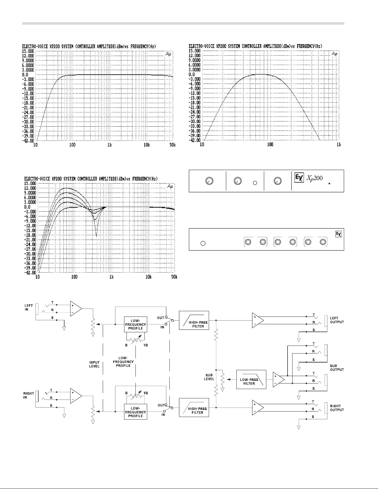
FIGURE 1 — Xp200A Frequency Response, Left and Right
Outputs, Profile Control Off (full counterclockwise)
FIGURE 2 — Xp200A Frequency Response, Subwoofer Output,
Profile Control Off (full counterclockwise)
FIGURE 3 — Xp200A Frequency Response, Left and Right
Outputs, Profile Control Advanced to Full Clockwise
in 3-dB Steps
FIGURE 6 — Xp200A Block Diagram
FIGURE 4 —Xp200A Front Panel
INPUT LEVEL
LOW FREQUENCY PROFILE
IN/OUT
FIGURE 5 — Xp200A Back Panel
AC POWER
SUB
RIGHT
SUB LEVEL
10010 0010
RIGHT
LEFT
RIGHT
LEFT
POWER/
CLIP
INPUTOUTPUT
LEFT
 Loading...