

Page 1
XLVC-TAE
X-Line Very Compact
Tilt-Angle Extender Bar
User Instructions
Tilt-Angle Extender Bar
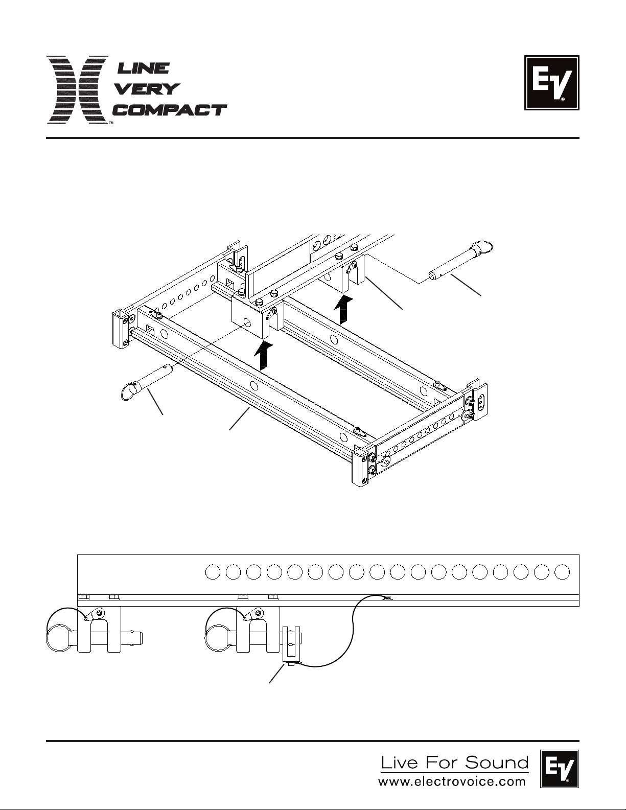
The X-Line Very Compact Tilt-Angle Extender Bar features a rigging attachment position to allow a single column composed of an X-Line
Very Compact Grid and Loudspeaker Array to be flown and tilted to obtain desired sound coverage. The X-Line Very Compact Tilt-Angle
Extender Bar offers up to 18 different angle positions either in declination or inclination depending on how the bar is positioned on the
grid.
Detent Pin
Tilt-Angle
Extender Bar
Detent Pin
Grid
Figure 1:
Attaching Grid to Tilt-Angle Extender Bar
9
18
17
16
Store Shackle on
Pin during Shipping
and Transportation
15
14
13
12
11
10
8
Figure 2:
Tilt-Angle Extender Bar Shipping/Transport Configuration
7
6
5
4
3
2
1
Page 2
Simplified Rigging Structural Ratings
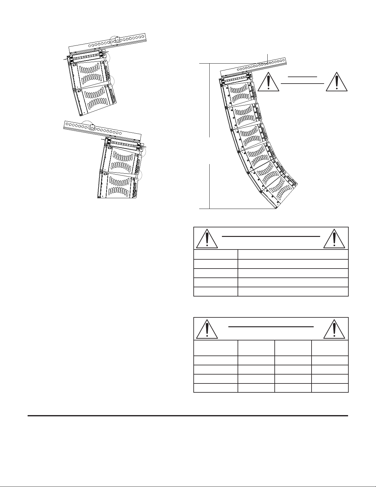
Tilting Down
(Hole #1 at Rear)
Tilting Up
(Hole #1 at Front)
Figure 3:
Tilt-Angle Extender Bar Declination and Incli-
nation with Attached Grid and Loudspeakers
Simplified Rigging-Rating Guidelines
1. These simplified rigging-rating guidelines provide ratings for
typical arrays based on the:
A. The total weight of the grid and all enclosures suspended
below the XLVC-TAE.
B. The pick-up hole on the XLVC-TAE.
C. The total height of the array from the pick-up hole in the XLVC-
TAE to the bottom of the bottom loudspeaker.
D. The assumption that one pick-up point will be used.
Determining the forces throughout an array requires complex calculations.
These guidelines eliminate the need for weight-distribution calculations by
using conservative working-load ratings. Other array configurations may
be permissable – Consult the XLVC Users Guide and LAPS Software.
2. Never exceed the weight limit for any XLVC-TAE pick-up hole.
3. Never exceed the height limit for any array using the XLVC-TAE.
4. Make sure that the two quick-release pins that secure the
spreader bars on the grid to the XLVC-TAE are fully locked.
5. Do not remove any bolts or dissasemble the XLVC-TAE.
6. Only use Electro-Voice rigging hardware.
7. Only suspend using the XLVC-Series grids.
8. Read the XLVC Users Guide before suspending any loud
speakers overhead.
9. All non-Electro-Voice hardware is the responsibility of others.
MAXIMUM
ARRAY HEIGHT:
Measured from
hole position used
to bottom of array.
100 in.
(2.54 m)
MAX
MAXIMUM ARRAY WEIGHT
XLVC GRID AND ALL BOXES BELOW
Hole Positions Maximum Allowable Weight of Array
1-2 400 lbs (181 kg)
3-4 480 lbs (218 kg)
5-6 560 lbs (254 kg)
7-18 600 lbs (272 kg)
TYPICAL ARRAY LIMITS
MAXIMUM NUMBER OF XLVC BOXES
Hole Positions XLD281/
XLD291
1-2 8 9 4
3-4 9 10 5
5-6 10 12 6
7-18 12 12 6
XLE181/
XLE191
XS212
Electro-Voice
12000 Portland Avenue South, Burnsville, MN 55337
Phone: 952/884-4051, Fax: 952/884-0043
®
www.electrovoice.com
© Bosch Communications Systems 11/2007
Part Number LIT000119 Rev A
U.S.A. and Canada only. For customer orders, contact Customer Service at:
800/392-3497 Fax: 800/955-6831
Europe, Africa, and Middle East only. For customer orders, contact Customer Service at:
+ 49 9421-706 0 Fax: + 49 9421-706 265
Other Internatonal locations. For customer orders, Contact Customer Service at:
+ 1 952 884-4051 Fax: + 1 952 887-9212
For warranty repair or service information, contact the Service Repair department at:
800/685-2606
For technical assistance, contact Technical Support at: 866/78AUDIO
Specifications subject to change without notice.
 Loading...