

Electro-Voice X-Line Very Compact, XLD281, XLE181, XS212 Rigging Manual
X-Line Very Compact Rigging Manual
(Preliminary)
ELECTRO-VOICE® X-Line Very CompactTM Rigging Manual

Table of Contents
Rigging-Safety Warning.............................................................................................................................................. 2
0 Introduction.............................................................................................................................................................. 3
1 XLVC Rigging System ............................................................................................................................................. 5
1.1 Overview of the XLVC Flying System ...................................................................................................... 5
1.2 Enclosure Rigging Hardware Details ....................................................................................................... 5
2 XLVC Rigging and Flying Techniques .................................................................................................................... 10
2.1 Array Considerations ............................................................................................................................. 10
2.2 Rigging an Array Using the XLVC Dollies............................................................................................... 10
3 Rigging-Strength Ratings, Safety Factors, and Special Safety Considerations...................................................... 17
3.1 Working-Load Limit (WLL) and Safety Factor Definitions....................................................................... 17
3.2 Structural Rating Overview .................................................................................................................... 18
3.3 Simplified Structural-Rating Guidelines.................................................................................................. 18
3.4 Complex Structural-Rating Analysis....................................................................................................... 21
3.5 Wind Loading......................................................................................................................................... 25
3.6 Electro-Voice Structural-Analysis Procedures........................................................................................ 26
4 Rigging Inspection and Precautions ...................................................................................................................... 27
References ............................................................................................................................................................... 29
Rigging References ..................................................................................................................................... 29
Mechanical Engineering References ........................................................................................................... 29
Websites...................................................................................................................................................... 29
Notes........................................................................................................................................................................ 30
ELECTRO-VOICE® X-Line Very CompactTM Rigging Manual1

Rigging-Safety Warning
This document details general rigging practices appropriate to the entertainment industry, as they
would apply to the rigging of Electro-Voice X-Line Very Compact (XLVC) loudspeaker systems. It
is intended to familiarize the reader with standard rigging hardware and techniques for suspending
XLVC loudspeaker systems overhead. Only persons with the knowledge of proper hardware and
safe rigging techniques should attempt to suspend any sound systems overhead. Prior to
suspending any Electro-Voice XLVC loudspeaker systems overhead, it is essential that the user
be familiar with the strength ratings, rigging techniques and special safety considerations outlined
in this manual. The rigging techniques and practices recommended in this manual are, of
necessity, in general terms to accommodate the many variations in loudspeaker arrays and
rigging configurations. As such, the user is expressly responsible for the safety of all specific
XLVC loudspeaker array designs and rigging configurations as implemented in practice.
All the general rigging material contained in this manual is based on the best available
engineering information concerning materials and practices, as commonly recognized in the
United States, and is believed to be accurate at the time of the original printing. As such, the
information may not be directly applicable in other countries. Furthermore, the regulations and
requirements governing rigging hardware and practices may be superseded by local regulations.
It is the responsibility of the user to ensure that any Electro-Voice loudspeaker system is
suspended overhead in accordance with all current federal, state and local regulations.
All specific material concerning the strength ratings, rigging techniques and safety considerations
for the XLVC loudspeaker systems is based on the best available engineering information
concerning the use and limitations of the products. Electro-Voice continually engages in testing,
research and development of its loudspeaker products. As a result, the specifications are subject
to change without notice. It is the responsibility of the user to ensure that any Electro-Voice
loudspeaker system is suspended overhead in accordance with the strength ratings, rigging
techniques and safety considerations given in this document and any manual update notices. All
non-Electro-Voice associated hardware items necessary to rig a complete XLVC loudspeaker
array (grids, chain hoists, building or tower supports and miscellaneous mechanical components)
are the responsibility of others.
Electro-Voice
February, 2005
ELECTRO-VOICE® X-Line Very CompactTM Rigging Manual 2
0. Introduction
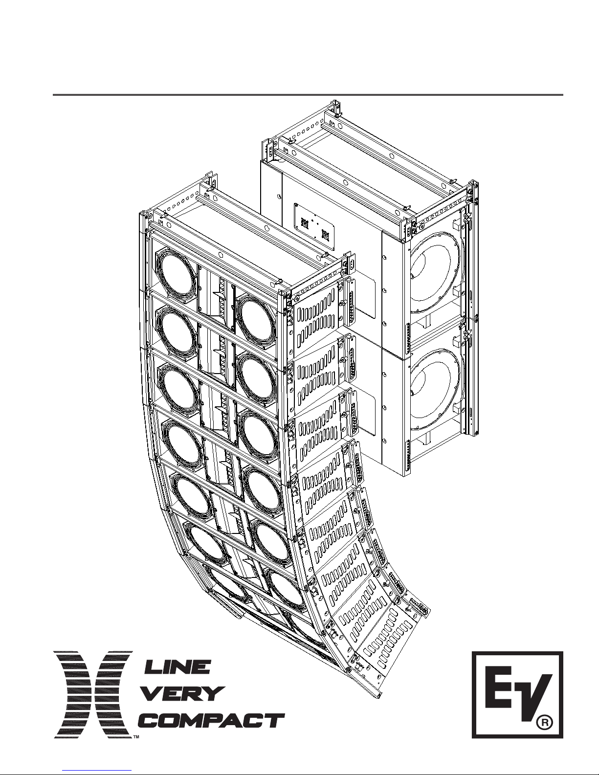
The X-Line Very Compact (XLVC) loudspeaker systems represent an important step in line-array
technology for small- and medium-scale sound reinforcement. The individual loudspeaker drivers,
acoustic lenses, acoustic waveguides, enclosures and rigging hardware were all designed
specifically for the XLVC product line to not only achieve the highest acoustic output with the
highest fidelity, but also to produce a precise wavefront from each element to achieve state-of-theart line-array performance. A brief description of the product line is included below. The XLVC
loudspeaker systems are shown in Figure 1 with key dimensions and weights.
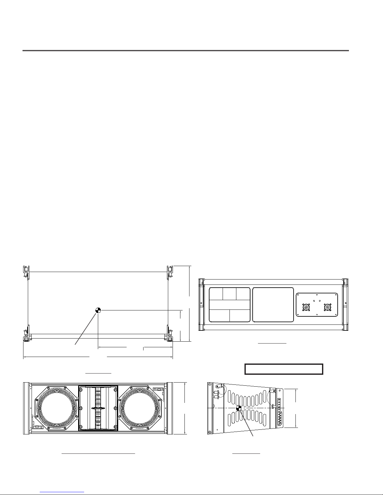
XLD281: Three-way, LF1/LF2/HF loudspeaker system with a 120°H x 10°V coverage pattern. The
system includes two DVN2080 8-inch (203-mm) LF drivers and two ND2S-16 2-inch (51-mm) HF
drivers. The XLD281 has a switchable crossover that allows either biamp or triamp operation. The
XLD281 utilizes an enclosure that is trapezoidal in the vertical plane (with an 10° total included
angle) and has XLVC 10° rigging tube and channel modules secured to the left and right
enclosure sides.
XLE181: Two-way, LF/HF loudspeaker system with a 120°H x 10°V coverage pattern. The system
includes one DVN2080 8-inch (203-mm) LF driver and two ND2S-16 2-inch (51-mm) HF drivers.
The XLE181 has a switchable crossover that allows either biamp or passive operation. The
XLE181 utilizes a narrower 10° trapezoidal enclosure than the XLD281 and has XLVC 10° rigging
tube and channel modules secured to the left and right enclosure sides.
XS212: Dual Side-Firing Bass System with two DVX3120 12-inch (305-mm) woofers. The XS212
utilizes an enclosure that is rectangular in shape and has XLVC elongated 20° rigging tube and
channel modules secured to the left and right enclosure sides.
14.52in
(369mm)
6.00in
(152mm)
Center of Gravity
28.58in
(726mm)
Top View
14.29in
(363mm)
9.90in
(251mm)
C
L
Rear View
Weight: 48 lb (21.8 kg)
7.41in
(188mm)
Front View (Without Grille)
Figure 1a:
Center of Gravity
Side View
XLD281 Loudspeaker System
ELECTRO-VOICE® X-Line Very CompactTM Rigging Manual3
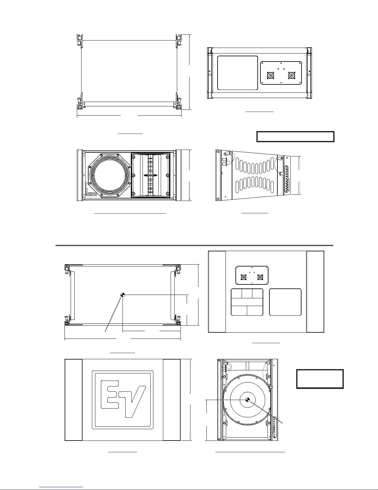
14.52in
(369mm)
20.30in
(516mm)
Top View
Front View (Without Grille)
Figure 1b:
XLE181 Loudspeaker System
9.90in
(251mm)
Rear View
Weight: 38 lb (17.2 kg)
7.41in
(188mm)
Side View
14.90in
(378mm)
7.45in
(189mm)
Center of Gravity
28.58in
(726mm)
14.29in
(363mm)
Rear View
Top View
Weight: 90 lb
(40.9 kg)
20.00in
(508mm)
10.00in
(254mm)
Front View
Figure 1c:
ELECTRO-VOICE® X-Line Very CompactTM Rigging Manual 4
XS212 Loudspeaker System
Side View (Without Grille)
Center of Gravity

1. X-Line Very Compact Rigging System
1.1 Overview of the XLVC Flying System
The XLVC loudspeaker systems have been designed to construct correct acoustic line arrays.
Acoustic line arrays typically consist of independent columns of loudspeaker systems that
acoustically and coherently sum to radiate cylindrical wavefronts. This simplifies the rigging
system.
The XLVC loudspeaker enclosures utilize a hinged rigging system that makes constructing arrays
easy, predictable and repeatable. This front-hinging rigging concept allows arrays to be accurately
constructed with the least possible spacing between enclosures. The front and back rigging
hardware for linking two enclosures together are captured as an integral part of the side rigging
tube and channel modules.
A basic array is shown in Figure 2 that illustrates the integral components that make up a typical
XLVC flying system. The XLD281 and XLE181 enclosures are vertically trapezoidal - taller at the
front than at the back. The enclosures are hinged at the front corners using rigging hardware
specially designed for the XLVC system. The enclosures are linked at the rear using rigging arms
that have multiple attachment positions. The different positions adjust how close the back corners
of the enclosures are pulled together; hence, adjusting the vertical angle of the bottom enclosure.
1.2 XLVC Enclosure Rigging Hardware Details
On each side of the enclosure are XLVC rigging tube and channel modules. All the rigging
hardware needed to fly a column of XLVC enclosures is an integral part of the high-strength
aluminum-alloy rigging tube and channel modules. The structural load is transmitted through the
modules minimizing the load on the loudspeaker enclosure shell. Figures 3a and 3b illustrate the
XLVC enclosure rigging hardware components. Figures 4a and 4b show key dimensions for the
rigging hardware.
At the front rigging module is a rectangular rigging tube. Captured inside the rigging tube is a
rigging connector called the hinge bar. The hinge bar is constructed from a high-strength
aluminum alloy. The hinge bar can slide out the top of the tube and be locked into position as
shown in Figure 2. The portion of the hinge bar sticking out the top would be inserted into the front
rigging tube of an enclosure above and pinned into place, linking the two enclosures together and
forming a hinging point between the two enclosures. The hinge bar can also be fully retracted
inside the tube for transportation.
Each hinge bar has two holes in the bar for rigging box-to-box or securing pins for transport. The
front rigging tube has two holes for pinning the bar in place to construct arrays or for transport. As
shown in Figures 3a and 3b, the bottom hole and pin on the bar locks the hinge bar in place at the
top of the tube. The exposed top hole and pin is then used to lock the hinge bar in the tube of an
enclosure above. For transportation, the hinge bar would be slid down inside the tube and would
be locked in the tube module using the two “transport holes” on the rear of the front rigging tube.
At the rear is a channel module with a vertical rigging slot. Captured inside the rigging slot is a
rigging connector called the swing arm. The swing arm is constructed from a high-strength
aluminum alloy. The swing arm can be pivoted to stick out the top as shown in Figures 3a and 3b.
At the bottom of the channel from the enclosure above, the rear rigging slot has a series of holes.
ELECTRO-VOICE® X-Line Very CompactTM Rigging Manual5
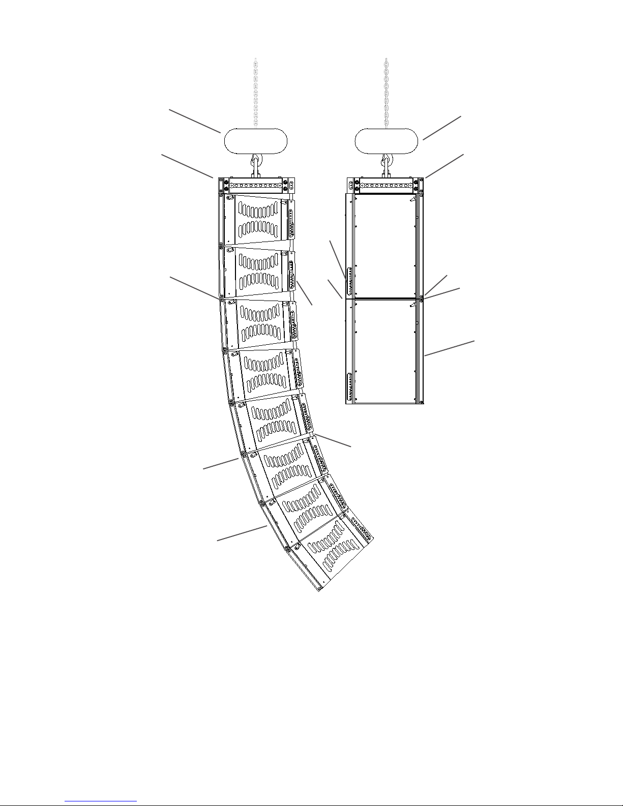
Hoist Motor
Hoist Motor
Grid
Quick-Release Pin
Eight XLD281
Enclosures Hinged at the
Front by the Extended
Hinge Bars and Front
Rigging Tube Modules
Quick-
Release
Pin
Swing
Arm
Quick-
Release
Pin
Swing Arm
Grid
Two XS212 Enclosures
the Extended Hinge Bars
Quick-
Release Pin
Hinge Bar
XS212 Enclosures
Hinged at the Front by
and Rigging Tube
Modules
Hinge Bar
Angles Between
Enclosures fixed by Pins
through the Swing Arms
and Rear Rigging Holes
XLD281 Enclosures
in the Channel Modules
Figure 2:
Typical XLVC Flying System (without Coupler Beam)
The swing arm from an enclosure below can be pivoted up so that the quick-release pin from the
enclosure below may be inserted through a hole in the rigging slot on the channel module above,
linking the two enclosures together. The vertical tilt angle of the bottom enclosure is then
determined by the hole in which the swing arm is pinned. The XLD281 and XLE181 enclosures
may be angled from 0° to 10° in 1° increments, while the XS212 enclosure may be angled from 0°
to 20° in 2° increments. The angle adjustment holes are detailed in figures 4a and 4b. This pin
fixes the maximum distance the back corners of the enclosures may be separated.
ELECTRO-VOICE® X-Line Very CompactTM Rigging Manual 6
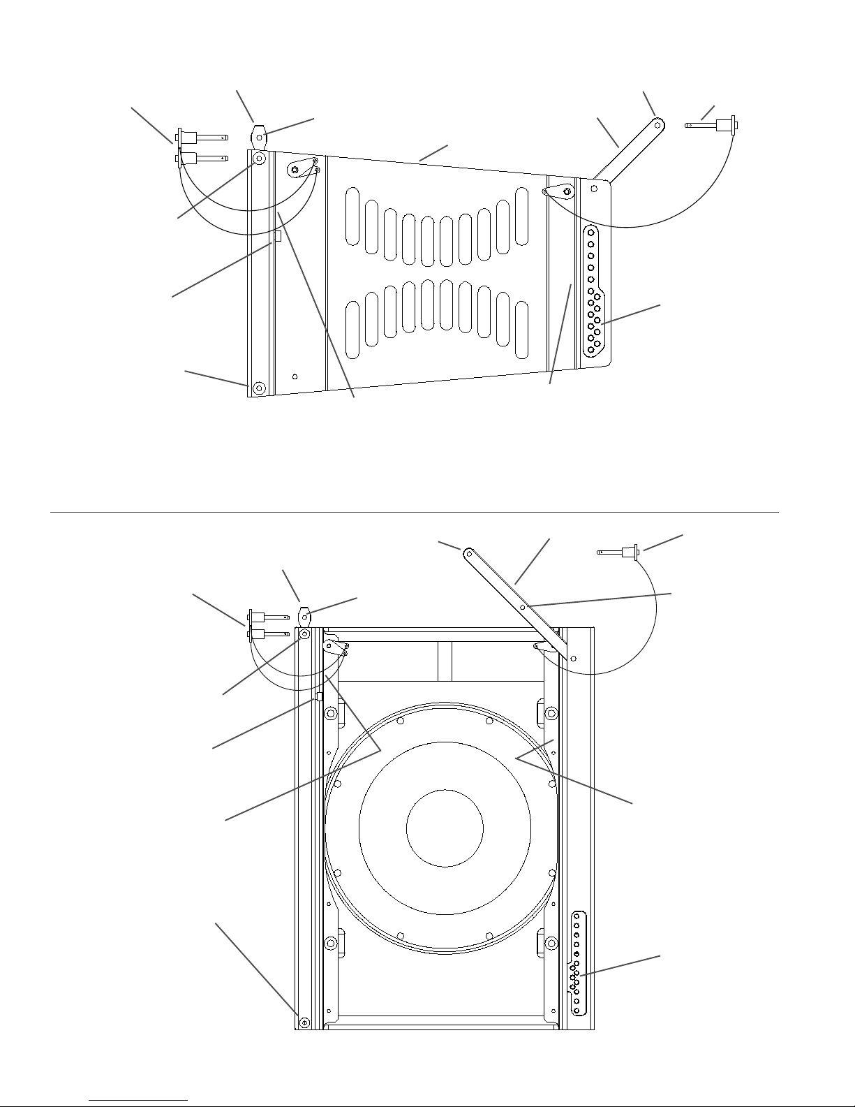
Front Hinge Bar
Quick-Release Pins
Hole in Front Rigging
Tube for Locking Pin
Shoulder Bolt for
Moving Hinge Bar
Up or Down
Hole in Front Rigging
Tube for Locking Pin
from Enclosure
Below
Figure 3a:
XLD281 and XLE181
Rigging Hardware
Hole in Hinge Bar for
Locking Pin
Transport Holes for
Storing Quick-
Release Pins During
Transport (Hinge Bar
Must Be Lowered)
Hole in Swing Arm for Locking Pin
Rear Swing Arm
XLD281 or XLE181
Enclosure
Transport Hole for
Storing Quick-Release
Pin During Transport
(Swing Arm Must Be
Lowered)
Quick-
Release Pin
Holes in Rear
Rigging Channel for
Locking Pin from
Enclosure Below
(These Holes
Determine Splay
Angle)
Quick-Release Pins
Hole in Front Rigging Tube
for Locking Pin
Shoulder Bolt for Moving
Hinge Bar Up or Down
Transport Holes for S toring
Quick-Release Pins During
Transport (Hinge Bar Must
Be Lowered)
Hole in Front Rigging Tube
for Locking Pin from
Enclosure Below
Figure 3b:
XS212 Rigging
Hardware
Front Hinge Bar
Hole in Swing Arm
for Locking Pin
Hole in Hinge Bar for
Locking Pin
Rear Swing Arm
ELECTRO-VOICE® X-Line Very CompactTM Rigging Manual7
Quick-Release Pin
Center Hole in
Rear Swing Arm
is for Grid Use
Only
Transport Hole for
Storing Quick-Release
Pin During Transport
(Swing Arm Must Be
Lowered)
Holes in Rear
Rigging Channel for
Locking Pin from
Enclosure Below
(These Holes
Determine Splay
Angle)
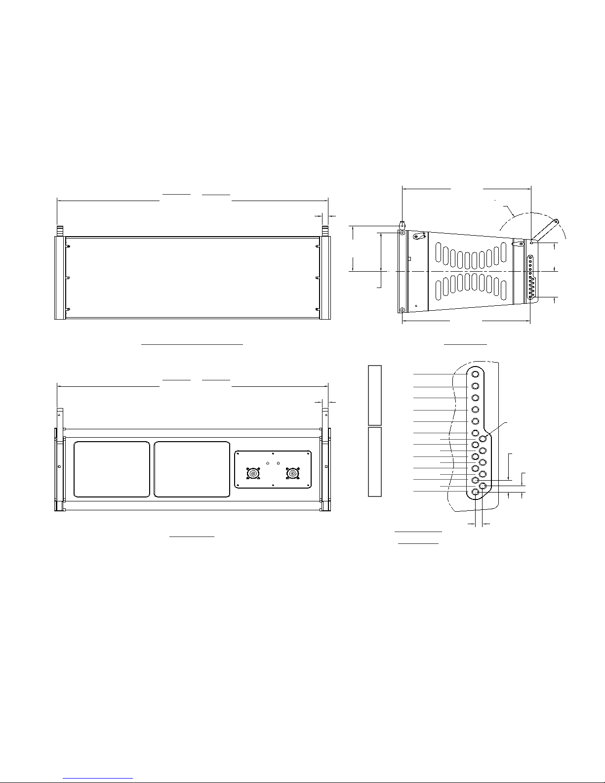
XLD281
28.13in
(715mm)
XLE181
19.85in
(505mm)
Front View (With Grille)
0.66in
Typ
(17mm)
5.42in
(138mm)
4.60in Typ
(117mm)
13.39in
(340mm)
R3.59in
(91mm)
3.39in
C
L
13.26in
(337mm)
(86mm)
3.05in
(78mm)
Side View
XLD281
28.13in
(715mm)
Rear View
XLE181
19.85in
(505mm)
0.66in
Typ
(17mm)
4° Hole
2° Hole
0° Hole
-2° Hole
-4° Hole
10° Hole
8° Hole
6° Hole
4° Hole
2° Hole
Full Range Only Subwoofer Only
0° Hole
Hole Detail
Figure 4a:
XLD281 and XLE181 Rigging Dimensions
9° Hole
7° Hole
5° Hole
3° Hole
1° Hole
Scale 3:1
Dia. 0.198in (x16)
(5mm)
0.468in Typ
(12mm)
0.240in Typ
(6mm)
0.251in
(6mm)
ELECTRO-VOICE® X-Line Very CompactTM Rigging Manual 8

13.39in
(340mm)
28.13in
(715mm)
Front View (With Grille)
28.13in
(715mm)
0.66in Typ
(17mm)
0.66in Typ
(17mm)
10.47in
(266mm)
9.65in Typ
(245mm)
R7.34in
(186mm)
3.59in
(91mm)
8.44in
(214mm)
C
L
9.04in
(230mm)
13.54in
(344mm)
Side View
Rear View
0° Hole
2° Hole
4° Hole
6° Hole
8° Hole
10° Hole
12/4° Hole
14/2° Hole
16/0° Hole
18/2°Up Hole
Sub/Full Range Subwoofer Only
20/4°Up Hole
5° Hole
3° Hole
1° Hole
Hole Detail
Scale 3:1
Figure 4b:
XS212 Rigging Dimensions
Dia. 0.198in (x14)
(5mm)
1.175in
(30mm)
0.466in
Typ
(12mm)
0.194in
(5mm)
ELECTRO-VOICE® X-Line Very CompactTM Rigging Manual9
 Loading...