

Page 1
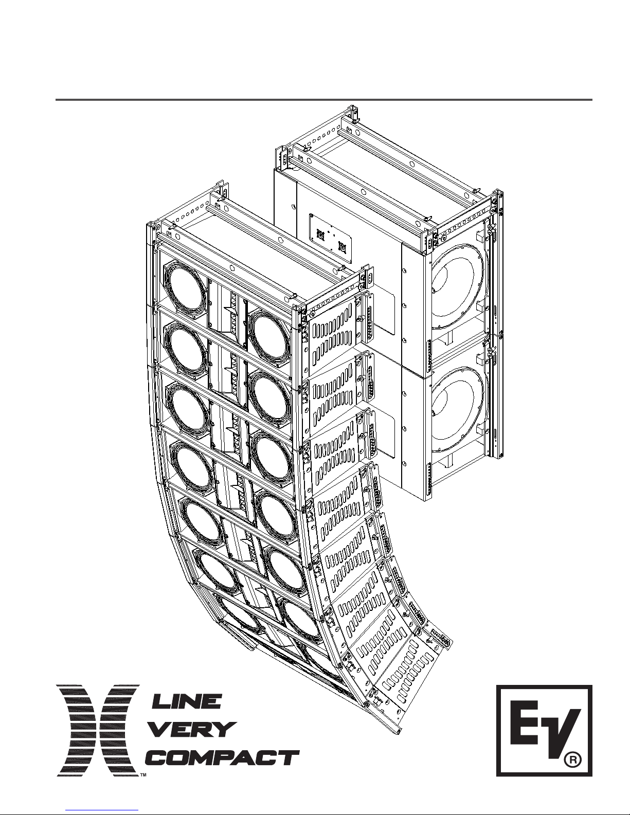
X-Line Very Compact Rigging Manual
(Preliminary)
ELECTRO-VOICE® X-Line Very CompactTM Rigging Manual
Page 2

Table of Contents
Rigging-Safety Warning.............................................................................................................................................. 2
0 Introduction.............................................................................................................................................................. 3
1 XLVC Rigging System ............................................................................................................................................. 5
1.1 Overview of the XLVC Flying System ...................................................................................................... 5
1.2 Enclosure Rigging Hardware Details ....................................................................................................... 5
2 XLVC Rigging and Flying Techniques .................................................................................................................... 10
2.1 Array Considerations ............................................................................................................................. 10
2.2 Rigging an Array Using the XLVC Dollies............................................................................................... 10
3 Rigging-Strength Ratings, Safety Factors, and Special Safety Considerations...................................................... 17
3.1 Working-Load Limit (WLL) and Safety Factor Definitions....................................................................... 17
3.2 Structural Rating Overview .................................................................................................................... 18
3.3 Simplified Structural-Rating Guidelines.................................................................................................. 18
3.4 Complex Structural-Rating Analysis....................................................................................................... 21
3.5 Wind Loading......................................................................................................................................... 25
3.6 Electro-Voice Structural-Analysis Procedures........................................................................................ 26
4 Rigging Inspection and Precautions ...................................................................................................................... 27
References ............................................................................................................................................................... 29
Rigging References ..................................................................................................................................... 29
Mechanical Engineering References ........................................................................................................... 29
Websites...................................................................................................................................................... 29
Notes........................................................................................................................................................................ 30
ELECTRO-VOICE® X-Line Very CompactTM Rigging Manual1
Page 3

Rigging-Safety Warning
This document details general rigging practices appropriate to the entertainment industry, as they
would apply to the rigging of Electro-Voice X-Line Very Compact (XLVC) loudspeaker systems. It
is intended to familiarize the reader with standard rigging hardware and techniques for suspending
XLVC loudspeaker systems overhead. Only persons with the knowledge of proper hardware and
safe rigging techniques should attempt to suspend any sound systems overhead. Prior to
suspending any Electro-Voice XLVC loudspeaker systems overhead, it is essential that the user
be familiar with the strength ratings, rigging techniques and special safety considerations outlined
in this manual. The rigging techniques and practices recommended in this manual are, of
necessity, in general terms to accommodate the many variations in loudspeaker arrays and
rigging configurations. As such, the user is expressly responsible for the safety of all specific
XLVC loudspeaker array designs and rigging configurations as implemented in practice.
All the general rigging material contained in this manual is based on the best available
engineering information concerning materials and practices, as commonly recognized in the
United States, and is believed to be accurate at the time of the original printing. As such, the
information may not be directly applicable in other countries. Furthermore, the regulations and
requirements governing rigging hardware and practices may be superseded by local regulations.
It is the responsibility of the user to ensure that any Electro-Voice loudspeaker system is
suspended overhead in accordance with all current federal, state and local regulations.
All specific material concerning the strength ratings, rigging techniques and safety considerations
for the XLVC loudspeaker systems is based on the best available engineering information
concerning the use and limitations of the products. Electro-Voice continually engages in testing,
research and development of its loudspeaker products. As a result, the specifications are subject
to change without notice. It is the responsibility of the user to ensure that any Electro-Voice
loudspeaker system is suspended overhead in accordance with the strength ratings, rigging
techniques and safety considerations given in this document and any manual update notices. All
non-Electro-Voice associated hardware items necessary to rig a complete XLVC loudspeaker
array (grids, chain hoists, building or tower supports and miscellaneous mechanical components)
are the responsibility of others.
Electro-Voice
February, 2005
ELECTRO-VOICE® X-Line Very CompactTM Rigging Manual 2
Page 4
0. Introduction
The X-Line Very Compact (XLVC) loudspeaker systems represent an important step in line-array
technology for small- and medium-scale sound reinforcement. The individual loudspeaker drivers,
acoustic lenses, acoustic waveguides, enclosures and rigging hardware were all designed
specifically for the XLVC product line to not only achieve the highest acoustic output with the
highest fidelity, but also to produce a precise wavefront from each element to achieve state-of-theart line-array performance. A brief description of the product line is included below. The XLVC
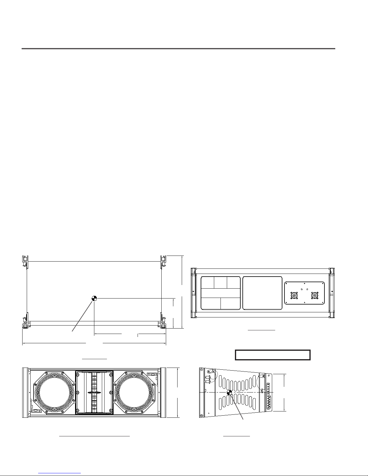
loudspeaker systems are shown in Figure 1 with key dimensions and weights.
XLD281: Three-way, LF1/LF2/HF loudspeaker system with a 120°H x 10°V coverage pattern. The
system includes two DVN2080 8-inch (203-mm) LF drivers and two ND2S-16 2-inch (51-mm) HF
drivers. The XLD281 has a switchable crossover that allows either biamp or triamp operation. The
XLD281 utilizes an enclosure that is trapezoidal in the vertical plane (with an 10° total included
angle) and has XLVC 10° rigging tube and channel modules secured to the left and right
enclosure sides.
XLE181: Two-way, LF/HF loudspeaker system with a 120°H x 10°V coverage pattern. The system
includes one DVN2080 8-inch (203-mm) LF driver and two ND2S-16 2-inch (51-mm) HF drivers.
The XLE181 has a switchable crossover that allows either biamp or passive operation. The
XLE181 utilizes a narrower 10° trapezoidal enclosure than the XLD281 and has XLVC 10° rigging
tube and channel modules secured to the left and right enclosure sides.
XS212: Dual Side-Firing Bass System with two DVX3120 12-inch (305-mm) woofers. The XS212
utilizes an enclosure that is rectangular in shape and has XLVC elongated 20° rigging tube and
channel modules secured to the left and right enclosure sides.
14.52in
(369mm)
6.00in
(152mm)
Center of Gravity
28.58in
(726mm)
Top View
14.29in
(363mm)
9.90in
(251mm)
C
L
Rear View
Weight: 48 lb (21.8 kg)
7.41in
(188mm)
Front View (Without Grille)
Figure 1a:
Center of Gravity
Side View
XLD281 Loudspeaker System
ELECTRO-VOICE® X-Line Very CompactTM Rigging Manual3
Page 5
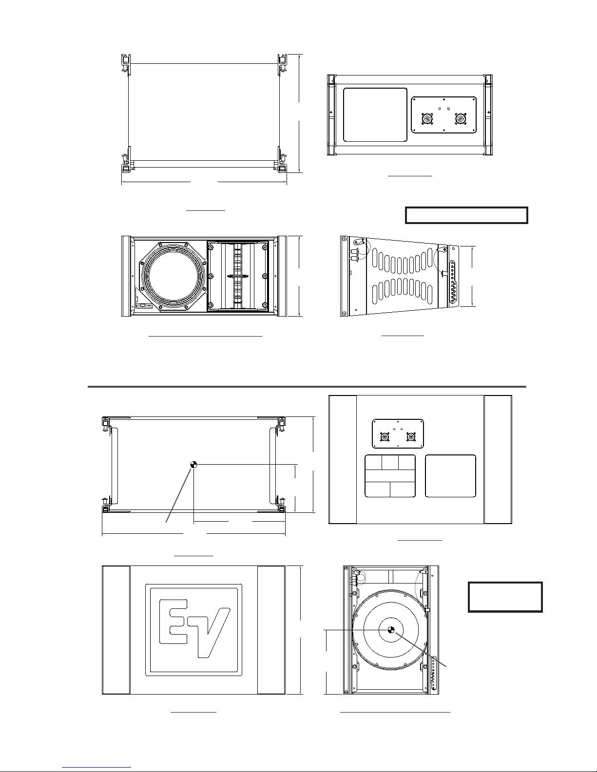
14.52in
(369mm)
20.30in
(516mm)
Top View
Front View (Without Grille)
Figure 1b:
XLE181 Loudspeaker System
9.90in
(251mm)
Rear View
Weight: 38 lb (17.2 kg)
7.41in
(188mm)
Side View
14.90in
(378mm)
7.45in
(189mm)
Center of Gravity
28.58in
(726mm)
14.29in
(363mm)
Rear View
Top View
Weight: 90 lb
(40.9 kg)
20.00in
(508mm)
10.00in
(254mm)
Front View
Figure 1c:
ELECTRO-VOICE® X-Line Very CompactTM Rigging Manual 4
XS212 Loudspeaker System
Side View (Without Grille)
Center of Gravity
Page 6

1. X-Line Very Compact Rigging System
1.1 Overview of the XLVC Flying System
The XLVC loudspeaker systems have been designed to construct correct acoustic line arrays.
Acoustic line arrays typically consist of independent columns of loudspeaker systems that
acoustically and coherently sum to radiate cylindrical wavefronts. This simplifies the rigging
system.
The XLVC loudspeaker enclosures utilize a hinged rigging system that makes constructing arrays
easy, predictable and repeatable. This front-hinging rigging concept allows arrays to be accurately
constructed with the least possible spacing between enclosures. The front and back rigging
hardware for linking two enclosures together are captured as an integral part of the side rigging
tube and channel modules.
A basic array is shown in Figure 2 that illustrates the integral components that make up a typical
XLVC flying system. The XLD281 and XLE181 enclosures are vertically trapezoidal - taller at the
front than at the back. The enclosures are hinged at the front corners using rigging hardware
specially designed for the XLVC system. The enclosures are linked at the rear using rigging arms
that have multiple attachment positions. The different positions adjust how close the back corners
of the enclosures are pulled together; hence, adjusting the vertical angle of the bottom enclosure.
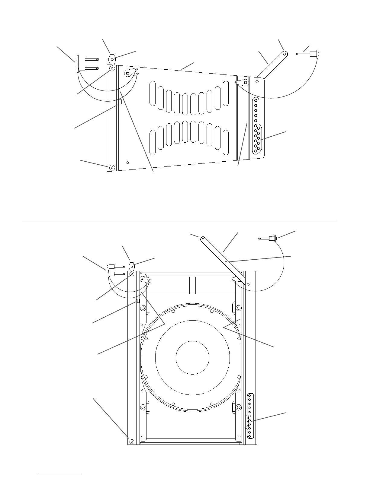
1.2 XLVC Enclosure Rigging Hardware Details
On each side of the enclosure are XLVC rigging tube and channel modules. All the rigging
hardware needed to fly a column of XLVC enclosures is an integral part of the high-strength
aluminum-alloy rigging tube and channel modules. The structural load is transmitted through the
modules minimizing the load on the loudspeaker enclosure shell. Figures 3a and 3b illustrate the
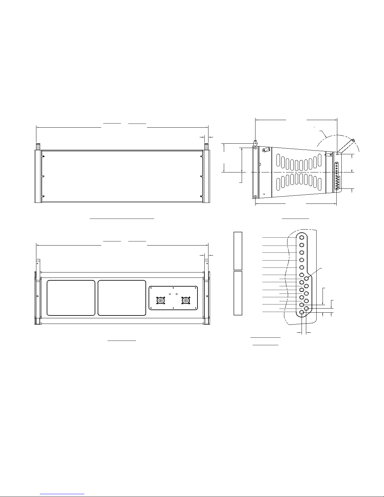
XLVC enclosure rigging hardware components. Figures 4a and 4b show key dimensions for the
rigging hardware.
At the front rigging module is a rectangular rigging tube. Captured inside the rigging tube is a
rigging connector called the hinge bar. The hinge bar is constructed from a high-strength
aluminum alloy. The hinge bar can slide out the top of the tube and be locked into position as
shown in Figure 2. The portion of the hinge bar sticking out the top would be inserted into the front
rigging tube of an enclosure above and pinned into place, linking the two enclosures together and
forming a hinging point between the two enclosures. The hinge bar can also be fully retracted
inside the tube for transportation.
Each hinge bar has two holes in the bar for rigging box-to-box or securing pins for transport. The
front rigging tube has two holes for pinning the bar in place to construct arrays or for transport. As
shown in Figures 3a and 3b, the bottom hole and pin on the bar locks the hinge bar in place at the
top of the tube. The exposed top hole and pin is then used to lock the hinge bar in the tube of an
enclosure above. For transportation, the hinge bar would be slid down inside the tube and would
be locked in the tube module using the two “transport holes” on the rear of the front rigging tube.
At the rear is a channel module with a vertical rigging slot. Captured inside the rigging slot is a
rigging connector called the swing arm. The swing arm is constructed from a high-strength
aluminum alloy. The swing arm can be pivoted to stick out the top as shown in Figures 3a and 3b.
At the bottom of the channel from the enclosure above, the rear rigging slot has a series of holes.
ELECTRO-VOICE® X-Line Very CompactTM Rigging Manual5
Page 7
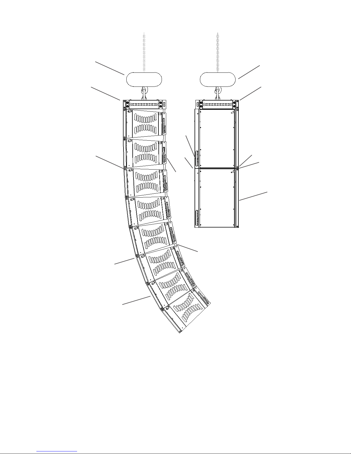
Hoist Motor
Hoist Motor
Grid
Quick-Release Pin
Eight XLD281
Enclosures Hinged at the
Front by the Extended
Hinge Bars and Front
Rigging Tube Modules
Quick-
Release
Pin
Swing
Arm
Quick-
Release
Pin
Swing Arm
Grid
Two XS212 Enclosures
the Extended Hinge Bars
Quick-
Release Pin
Hinge Bar
XS212 Enclosures
Hinged at the Front by
and Rigging Tube
Modules
Hinge Bar
Angles Between
Enclosures fixed by Pins
through the Swing Arms
and Rear Rigging Holes
XLD281 Enclosures
in the Channel Modules
Figure 2:
Typical XLVC Flying System (without Coupler Beam)
The swing arm from an enclosure below can be pivoted up so that the quick-release pin from the
enclosure below may be inserted through a hole in the rigging slot on the channel module above,
linking the two enclosures together. The vertical tilt angle of the bottom enclosure is then
determined by the hole in which the swing arm is pinned. The XLD281 and XLE181 enclosures
may be angled from 0° to 10° in 1° increments, while the XS212 enclosure may be angled from 0°
to 20° in 2° increments. The angle adjustment holes are detailed in figures 4a and 4b. This pin
fixes the maximum distance the back corners of the enclosures may be separated.
ELECTRO-VOICE® X-Line Very CompactTM Rigging Manual 6
Page 8
Front Hinge Bar
Quick-Release Pins
Hole in Front Rigging
Tube for Locking Pin
Shoulder Bolt for
Moving Hinge Bar
Up or Down
Hole in Front Rigging
Tube for Locking Pin
from Enclosure
Below
Figure 3a:
XLD281 and XLE181
Rigging Hardware
Hole in Hinge Bar for
Locking Pin
Transport Holes for
Storing Quick-
Release Pins During
Transport (Hinge Bar
Must Be Lowered)
Hole in Swing Arm for Locking Pin
Rear Swing Arm
XLD281 or XLE181
Enclosure
Transport Hole for
Storing Quick-Release
Pin During Transport
(Swing Arm Must Be
Lowered)
Quick-
Release Pin
Holes in Rear
Rigging Channel for
Locking Pin from
Enclosure Below
(These Holes
Determine Splay
Angle)
Quick-Release Pins
Hole in Front Rigging Tube
for Locking Pin
Shoulder Bolt for Moving
Hinge Bar Up or Down
Transport Holes for S toring
Quick-Release Pins During
Transport (Hinge Bar Must
Be Lowered)
Hole in Front Rigging Tube
for Locking Pin from
Enclosure Below
Figure 3b:
XS212 Rigging
Hardware
Front Hinge Bar
Hole in Swing Arm
for Locking Pin
Hole in Hinge Bar for
Locking Pin
Rear Swing Arm
ELECTRO-VOICE® X-Line Very CompactTM Rigging Manual7
Quick-Release Pin
Center Hole in
Rear Swing Arm
is for Grid Use
Only
Transport Hole for
Storing Quick-Release
Pin During Transport
(Swing Arm Must Be
Lowered)
Holes in Rear
Rigging Channel for
Locking Pin from
Enclosure Below
(These Holes
Determine Splay
Angle)
Page 9
XLD281
28.13in
(715mm)
XLE181
19.85in
(505mm)
Front View (With Grille)
0.66in
Typ
(17mm)
5.42in
(138mm)
4.60in Typ
(117mm)
13.39in
(340mm)
R3.59in
(91mm)
3.39in
C
L
13.26in
(337mm)
(86mm)
3.05in
(78mm)
Side View
XLD281
28.13in
(715mm)
Rear View
XLE181
19.85in
(505mm)
0.66in
Typ
(17mm)
4° Hole
2° Hole
0° Hole
-2° Hole
-4° Hole
10° Hole
8° Hole
6° Hole
4° Hole
2° Hole
Full Range Only Subwoofer Only
0° Hole
Hole Detail
Figure 4a:
XLD281 and XLE181 Rigging Dimensions
9° Hole
7° Hole
5° Hole
3° Hole
1° Hole
Scale 3:1
Dia. 0.198in (x16)
(5mm)
0.468in Typ
(12mm)
0.240in Typ
(6mm)
0.251in
(6mm)
ELECTRO-VOICE® X-Line Very CompactTM Rigging Manual 8
Page 10

13.39in
(340mm)
28.13in
(715mm)
Front View (With Grille)
28.13in
(715mm)
0.66in Typ
(17mm)
0.66in Typ
(17mm)
10.47in
(266mm)
9.65in Typ
(245mm)
R7.34in
(186mm)
3.59in
(91mm)
8.44in
(214mm)
C
L
9.04in
(230mm)
13.54in
(344mm)
Side View
Rear View
0° Hole
2° Hole
4° Hole
6° Hole
8° Hole
10° Hole
12/4° Hole
14/2° Hole
16/0° Hole
18/2°Up Hole
Sub/Full Range Subwoofer Only
20/4°Up Hole
5° Hole
3° Hole
1° Hole
Hole Detail
Scale 3:1
Figure 4b:
XS212 Rigging Dimensions
Dia. 0.198in (x14)
(5mm)
1.175in
(30mm)
0.466in
Typ
(12mm)
0.194in
(5mm)
ELECTRO-VOICE® X-Line Very CompactTM Rigging Manual9
Page 11

2. XLVC Rigging and Flying Techniques
2.1 Array Considerations
The XLVC loudspeaker systems have been specifically designed to construct acoustically
coherant line-arrays. Line-array systems typically consist of independent columns of loudspeaker
enclosures. The most common implementation would be a stereo sound reinforcement system
with two columns (left and right). Additional columns of loudspeakers are sometimes added to
cover different seating sections of a venue – seating areas that wrap around the side or back of a
stage, for example, or for applications with the requirement of a center channel for speech.
The XLVC line arrays will consist of columns of XLD281 or XLE181 120°H x 10°V full-range
systems. The exact number of XLVC loudspeaker systems in a column will vary depending on the
vertical acoustic coverage required for the specific venue. Furthermore, the relative vertical angles
between the boxes will also depend on the venue’s acoustic coverage requirements. (Acoustic
design techniques are outside the scope of this document and the reader is directed to the XLVC
LAPS modeling software available from the Electro-Voice website for acoustic design assistance.)
It is also possible to construct subwoofer line arrays using the XS212 systems, or implement
subwoofers in the same column as the XLD281 full-range elements.
Although the full-range XLVC loudspeaker systems shown in Figure 1 are not completely
symmetrical, their acoustical polar responses are substantially symmetrical because the highfrequency sections (in the XLD281) are in the center of the enclosures. Thus, stereo left and right
arrays, or left-center-right arrays may be constructed with the loudspeakers in their normal rightside-up orientation as shown in Figure 1.
2.2 Rigging an Array Using the XLVC Dollies
Attach the top enclosure in the array to the grid, as shown in Figure 6. (Only an XLVC compatible
grid can be used with an XLVC array.) The grid has front rigging tubes similar to the enclosures.
Slide the front hinge bar of the top enclosure into the front tube of the grid using the same technique that was used to link two enclosures.
MAKE SURE THAT THE QUICK-RELEASE PINS ON THE HINGE BARS FULLY
LOCK INTO THE ROUND HOLES IN THE FRONT RIGGING TUBES ON BOTH
THE ENCLOSURE AND THE BOTTOM HOLE OF THE GRID.
The grid also has a rear rigging channel similar to the enclosures, except that the grid only has
three attachment holes available. Unlock the rear swing arm from the top enclosure by removing
the quick-release pin from the rear rigging channel on the enclosure. Pivot the rear swing arm on
the enclosure up into the rear rigging channel on the grid. Insert the quick-release pin from the
grid through one of the three holes in the rear rigging channel on the grid (top hole is 0°, middle
hole is 2° up, and bottom hole is 4° up) and through the hole in the swing arm. Repeat the process for the other side of the enclosure and grid.
MAKE SURE THAT THE QUICK-RELEASE PIN IS FULLY LOCKED IN THE REAR
OF THE GRID AND THAT THE SWING ARM FROM THE ENCLOSURE IS
SECURED.
ELECTRO-VOICE® X-Line Very CompactTM Rigging Manual 10
Page 12
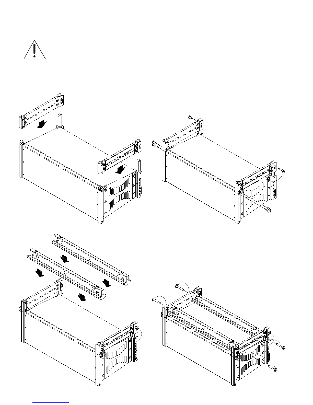
ON EACH ENCLOSURE, AL WAYS MAKE SURE THAT THE LEFT AND RIGHT SWING ARMS
ON THA T ENCLOSURE ARE LOCKED INTO THE SAME HOLES FOR THE SAME VERTICAL
SPLAY ANGLE. THE QUICK-RELEASE LOCKING PINS ARE TETHERED TO THE REAR
RIGGING FRAME WITH A LANYARD. THE QUICK-RELEASE PINS MUST ONLY BE LOCKED
IN THE REAR RIGGING HOLES ON THE FRAME TO WHICH IT IS TETHERED. NEVER
USE THE PINS FROM ONE ENCLOSURE TO LOCK INTO ANOTHER ENCLOSURE.
Step 1:
Assemble Sidearms to Rigging at top of the
Enclosure.
Step 3:
Step 2:
Insert Quick-Release Pins through Enclosure
Rigging and Sidearms.
Step 4:
Assemble Spreader Bar(s) to Sidearms.
Grid Rigging Assembly
Insert Quick-Release Pins through Sidearms
and Spreader Bar(s) using the hole locations
from LAPS.
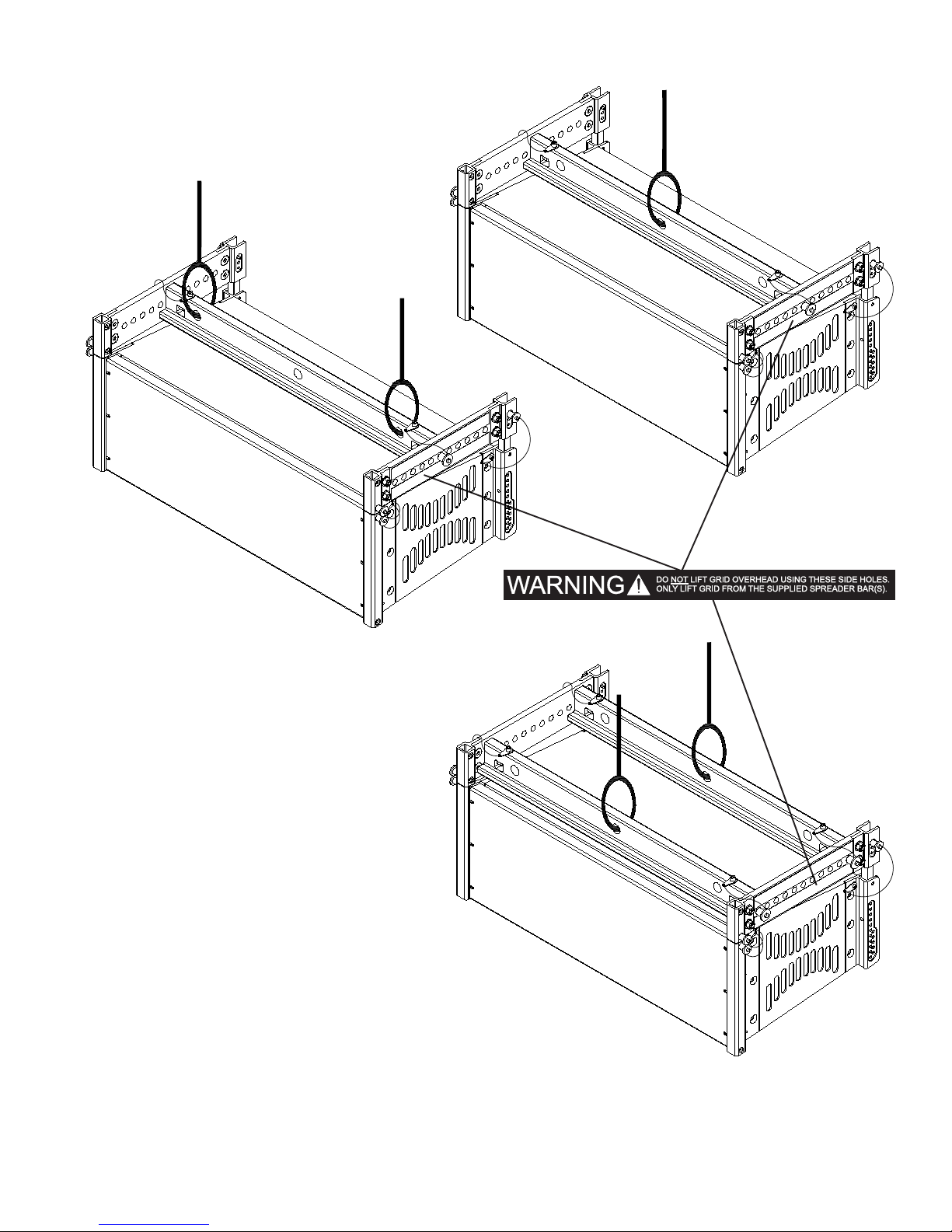
See next page for fully assembled configurations.
Figure 5a:
ELECTRO-VOICE® X-Line Very CompactTM Rigging Manual11
Page 13
ELECTRO-VOICE® X-Line Very CompactTM Rigging Manual 12
Figure 5b:
Grid Rigging Configurations
Page 14
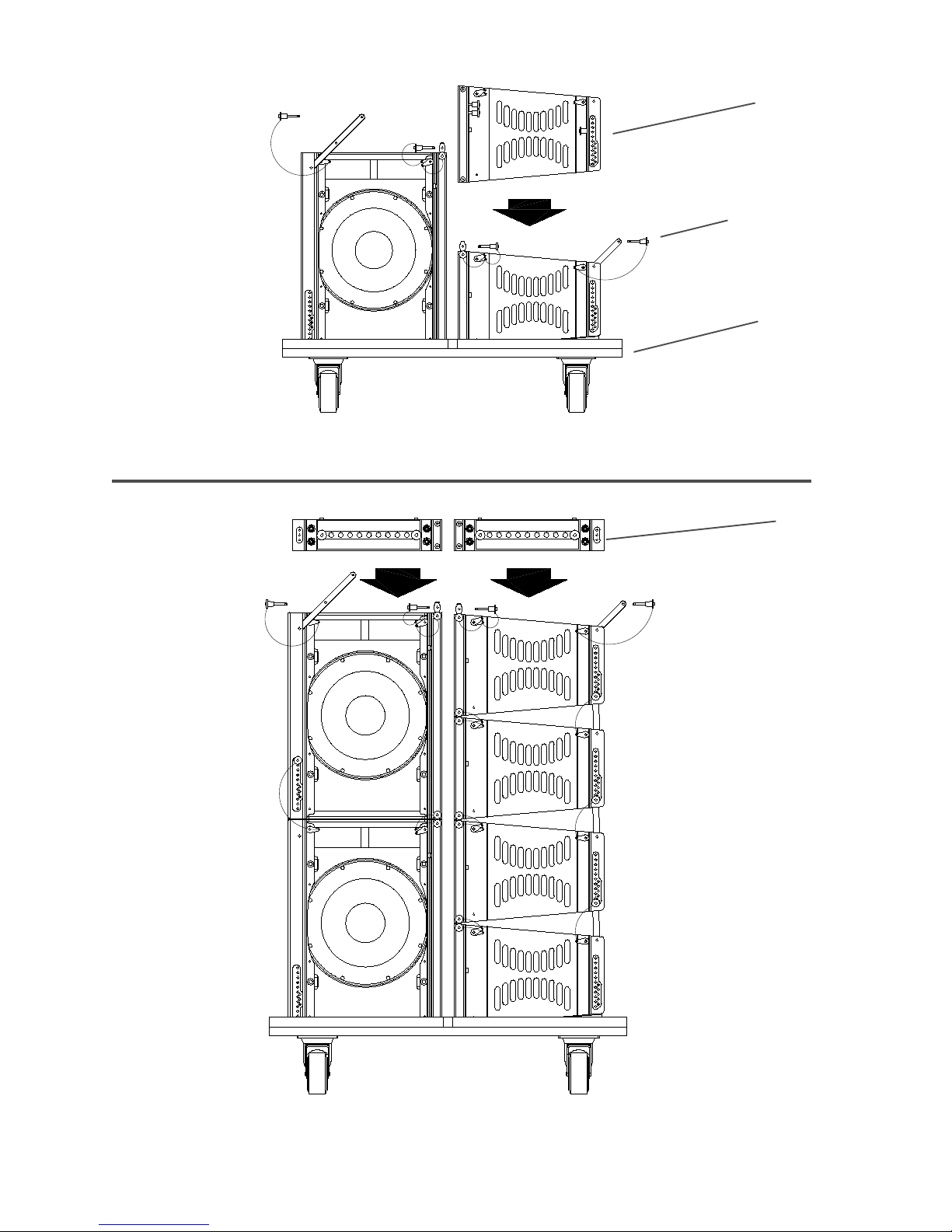
Figure 6a:
Stacking and Flying Arrays using the XLVC Dolly - Step 1
Additional
Enclosures
Quick-Release Pins
Dolly Base
Grids
Stacking and Flying Arrays using the XLVC Dolly - Step 2
13
Figure 6b:
ELECTRO-VOICE® X-Line Very CompactTM Rigging Manual
Page 15
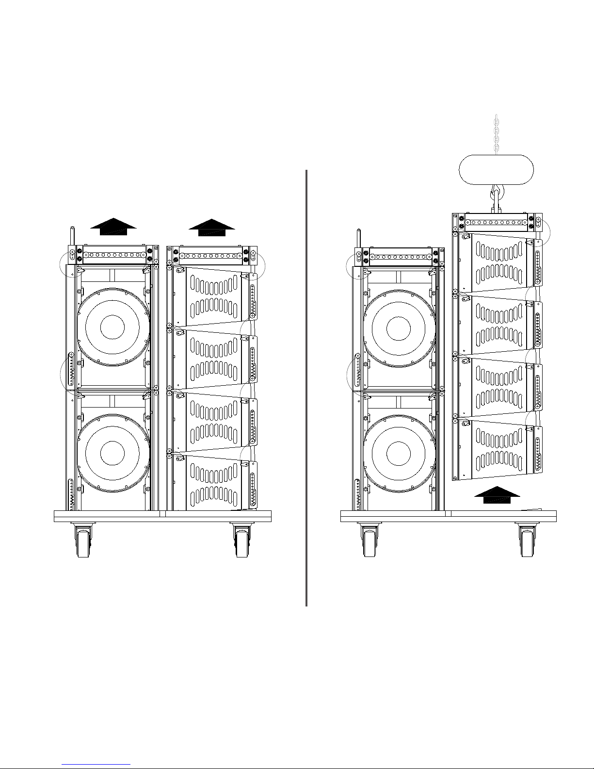
Figure 6c:
Stacking and Flying Arrays using
the XLVC Dolly - Step 3
Figure 6d:
Stacking and Flying Arrays using
the XLVC Dolly - Step 4
ELECTRO-VOICE® X-Line Very CompactTM Rigging Manual
14
Page 16
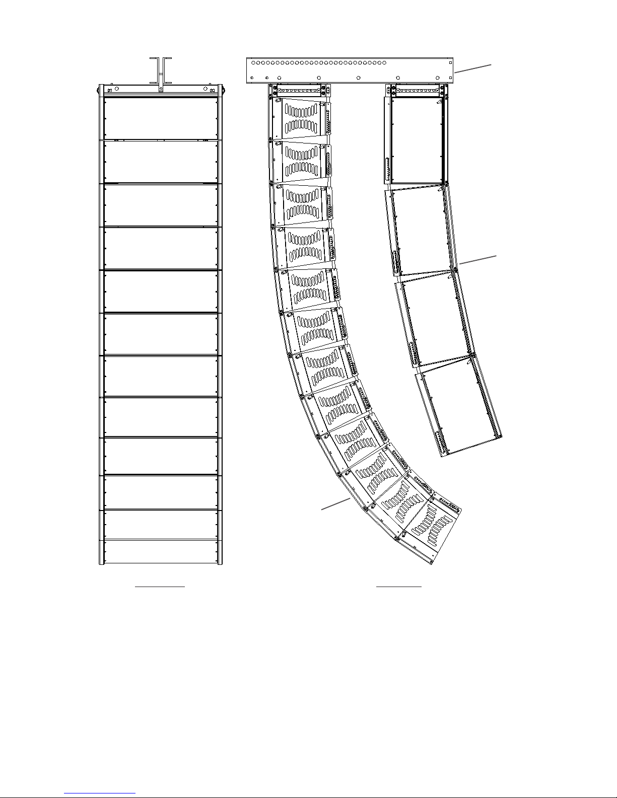
Coupler Beam
XS212
Enclosures
Front View Side View
Flying an Array of XS212’s behind XLD281’s using the XLVC Coupler Beam
(audience only sees XLD281’s)
XLD281
Enclosures
Figure 7a:
ELECTRO-VOICE® X-Line Very CompactTM Rigging Manual15
Page 17
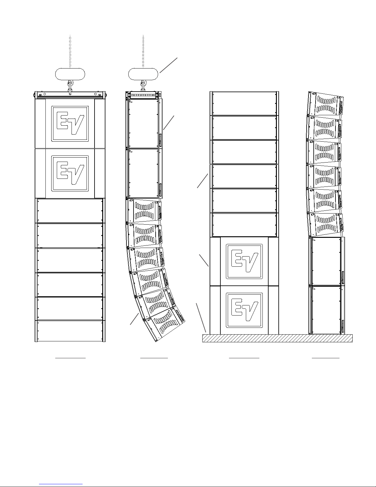
Hoist
Motors
XS212
Enclosures
XLD281
Enclosures
XS212
Enclosures
Ground
XLD281
Enclosures
Front View Side View Front View Side View
Figure 7b:
Flying an Array of XLD281’s under
XS212’s using Interactive Rigging
Groundstacking XLD281’s over XS212’s
using Interactive Rigging
Figure 7c:
ELECTRO-VOICE® X-Line Very CompactTM Rigging Manual 16
Page 18

3. Rigging-Strength Ratings, Safety Factors, and
Special Safety Considerations
3.1 Working-Load Limit and Safety Factor Definitions
The structural ratings for all of the XLVC rigging components and complete loudspeaker systems
are based on test results in which parts were stressed to failure. Manufacturers typically present
the structural-strength ratings of mechanical components or systems as either the working-load
limit (WLL) or the ultimate-break strength. Electro-Voice chooses to present the structural-load
ratings of the XLVC loudspeaker systems as the working-load limit. The working-load-limit rating
represents the maximum load that should ever be applied to a mechanical component or system.
THE USER SHOULD NEVER APPLY A LOAD THAT EXCEEDS THE WORKINGLOAD LIMITS OF ANY OF THE RIGGING COMPONENTS OR COMPLETE
LOUDSPEAKER SYSTEMS DESCRIBED IN THIS MANUAL.
The working-load limits for the XLVC rigging components and complete loudspeaker systems
described in this manual are based on a minimum of an 8:1 safety factor. The safety factor is
defined as the ratio of the ultimate-break strength divided by the working-load limit, where the
ultimate-break strength represents the force at which a part will structurally fail. For example, if a
part has working-load limit of 1,000 lb (454 kg), it would not structurally fail until a force of at least
8,000 lb (3,629 kg) was applied, based on a 8:1 safety factor. However, the user should never
apply a load to that part that exceeds 1,000 lb (454 kg). The safety factor provides a margin of
safety above the working-load limit to accommodate normal dynamic loading and normal wear.
CAUTIONS for Working-Load Limits and Safety Factors
The working-load limits defined by the manufacturer of any rigging component should never be
exceeded. Electro-Voice bases the working-load limits of its XLVC products on a minimum of an
8:1 safety factor. Other manufacturers of rigging components may base their working-load limits
on safety factors other than 8:1. For example, 5:1 safety factors are fairly common amongst
rigging manufacturers because many regulatory agencies call for a minimum safety factor of 5:1.
When an XLVC loudspeaker system is installed where local regulations only require a safety
factor of 5:1, Electro-Voice insists that the working-load limits of the XLVC rigging never be
exceeded and that an 8:1 safety factor be maintained for the XLVC loudspeakers.
The user is cautioned that some local regulations may require safety factors higher than 8:1. In
that circumstance, Electro-Voice insists that the user maintain the higher safety factor as required
by the local regulations throughout the entire XLVC installation. It is the responsibility of the user
to make sure that any XLVC installation meets any applicable local, state or federal safety
regulations.
ELECTRO-VOICE® X-Line Very CompactTM Rigging Manual17
Page 19

3.2 Structural Rating Overview
There are two independent strength ratings that, together, give a complete description of the
overall structural performance capabilities of any XLVC loudspeaker system. They are defined as
follows:
1. The strength of each individual rigging point; which is the combined strength of the rigging
tube and channel, the rigging tube and channel components (front hinge bars, rear swing arm,
quick-release pins, etc.) and the enclosure.
2. The total strength of the overall enclosure; which is a function of the combined forces from
all of the rigging points acting on the rigging components and enclosure as a whole.
The array designer must be aware of the working-load-limit ratings and the loads being applied to
the individual rigging points and the overall enclosure. An XLVC loudspeaker system is only as
strong as its weakest link. It is usually the case that one of the working-load limits will be approached sooner that the other.
WHEN SUSPENDING ANY XLVC LOUDSPEAKER SYSTEM OVERHEAD, THE
WORKING-LOAD LIMITS MUST NEVER BE EXCEEDED FOR EACH INDIVIDUAL
RIGGING POINT, OR THE OVERALL ENCLOSURE.
The forces acting on each individual rigging point and on the overall enclosures in an XLVC flying
system will vary with each array configuration. Determining the forces throughout an array requires complex mathematical calculations. Electro-Voice engineers have, however, defined a set
of simplified structural-rating guidelines that eliminate the need for the complex calculations for
most array configurations. The interaction of the complex forces throughout arrays were analyzed
to develop this set of conservative guide-lines, presented below, to enable a rigger to immediately
determine on site whether or not an array is safe without having to make weight-distribution calculations. The structural-strength ratings of the individual rigging points and the overall XLVC enclosures are also presented below so that a complex structural analysis can be made for any array
configuration. The reader should consult an experienced structural engineer to perform the complex structural analysis.
The reader is directed to the References section of this manual for a list of rigging references (for
background in general rigging practice) and mechanical engineering references (for background in
structural engineering analysis).
3.3 Simplified Structural-Rating Guidelines
Electro-Voice engineers have defined a set of simplified structural-rating guidelines that will enable a rigger to immediately evaluate the safety of an XLVC system on site without having to
make complex force-distribution calculations. A combination of destructive testing and computer
modeling were used to analyze the complex forces throughout arrays. Conservative working-load
ratings were utilized to simplify the guidelines. Therefore, array configurations other than those
illustrated in these simplified guidelines may be permissible for those applications, consult section
3.4, Complex Structural-Rating Analysis for a detailed structural analysis.
The simplified structural-rating guidelines are shown in Figure 8. (Note that there is a label on the
back of each flying XLVC loudspeaker enclosure that includes the graphics shown in Figure 8.)
ELECTRO-VOICE® X-Line Very CompactTM Rigging Manual 18
Page 20

These guidelines provide a simplified rating for typical arrays based on the:
1. Vertical angle of each enclosure
2. Total weight of that enclosure plus all of the enclosures and rigging hung below it.
3. Angles of the force components on the front hinge bars and rigging tubes relative to the
enclosures.
4. Angles of the force components on the rear swing arms, quick-release pins and rigging
channels relative to the enclosures.
Specifications
Pending
Figure 8:
Simplified XLVC Rigging-Rating Guidelines
ELECTRO-VOICE® X-Line Very CompactTM Rigging Manual19
Page 21

Figure 8 includes a graph of the working-load weight-versus-angle limit rating for the XLVC enclosures. This working-load weight limit is applicable to every enclosure in an array, and includes the
weight of that enclosure plus the total weight of all enclosures, rigging hardware and cabling
suspended below it. The absolute enclosure angle is the vertical angle of that enclosure, where 0°
represents an upright enclosure facing straight ahead (0° elevation angle). These working-Ioadversus-angle limits take into account the complex forces generated in the front hinge bars, the
rear swing arms, the quick-release pins, the rigging tubes and channels, the enclosures and the
(optional) pull-up line, as a result of the complex weight distribution throughout the array.
Also included in the simplified structural-rating guidelines in Figure 8 are side-to-side and front-toback angle limits for the front hinge bars and rear swing arms on the top enclosure.
WHEN APPLYING THE SIMPLIFIED STRUCTURAL RATING GUIDELINES TO
ANY XLVC LOUDSPEAKER SYSTEM SUSPENDED OVERHEAD, THE USER
MUST OBEY THE FOLLOWING RULES:
1. Never exceed the working-Ioad-versus-angle limit for any enclosure in the array.
2. Never exceed the side-to-side angle limits for the front hinge bar assemblies on any
enclosure.
3. Never exceed the side-to-side angle limits for the rear swing arm assemblies on any
enclosure.
4. Always make sure that every front hinge bar is securely locked in the front rigging tube on
every enclosure (and grid, when applicable) before lifting overhead.
5. Always make sure that every rear swing arm is securely locked in the rear rigging channel
with the quick-release pins on every enclosure (and grid, when applicable) before lifting
overhead.
6. If a pull-up grid is used, never exceed the side-to-side angle limits for the pull-up grid.
Discussion of Array Examples: For example, if the top enclosure in a column was angled down
30°, the enclosure working-Ioad-versus-angle limit from the simplified structural-rating guidelines
shown in Figure 8 would indicate that a total of 800 pounds (363 kg) could be safely suspended.
This would include the weight of the top enclosure plus all of the enclosures and rigging suspended below.
If, however, the top enclosure in a column was angled up 30°, the total allowable weight would
then only be 764 lb (347 kg) - including the weight of the top enclosure plus all of the enclosures
and rigging suspended below. The enclosure working-load-versus-angle limit shown in Figure 8
not only applies to the top enclosure in an array column, but also applies to every enclosure in an
array column. In arrays where a pull-up grid is not used, the top enclosure is always the limiting
factor because it supports the most weight. However, in arrays where a pull-up grid is used to
achieve substantial downward angles, it is possible that a lower enclosure could be the limiting
factor.
ELECTRO-VOICE® X-Line Very CompactTM Rigging Manual 20
Page 22

3.4 Complex Structural-Rating Analysis
For a complete structural-rating analysis, the forces in each individual piece of attachment hardware throughout the XLVC system must be determined, as well as the forces on each enclosure.
Determining these forces requires complex mathematical calculations. All of these forces must
then be compared to the working-load limits detailed below for each of the rigging points and the
overall enclosures.
The reader should consult an experienced structural engineer to perform the complex structural
analysis.
WHEN SUSPENDING ANY XLVC LOUDSPEAKER SYSTEM OVERHEAD, THE
WORKING-LOAD LIMITS MUST NEVER BE EXCEEDED FOR EACH INDIVIDUAL
RIGGING POINT, AND THE OVERALL ENCLOSURE.
XLD281, XLE181 and XS212 Front Rigging Structural-Strength Ratings
The working-load limit of each of the front rigging points on the XLVC enclosures is dependent
upon the hinge bar assembly, the rigging tube and channel assemblies, the enclosure and the
angle of pull. The structural-strength ratings for the front rigging points are identical for the
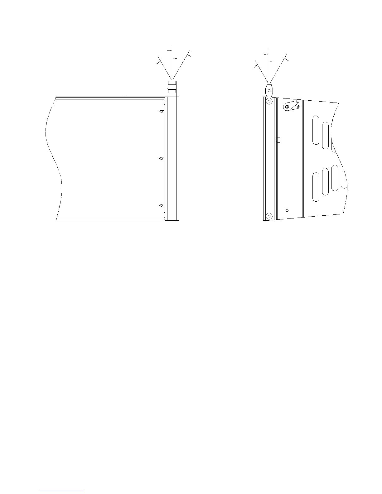
XLD281, XLE181, and XS212, and are shown in Figure 9. The enclosures have two rigging points
at the front. The structural ratings shown in Figure 9 are for a single rigging attachment point.
Each rigging point has the same rating.
The front-to-back structural-strength ratings for the front rigging points shown in Figure 9 cover a
full 360° rotation. Although it is not possible to put the front button bars into tension over 360°, it is
possible for the hinge bars to go into compression with some array configurations. Therefore, the
360° rating is necessary to accommodate both tension and compression. It also should be noted
that the XLVC front rigging is only rated for use over side-to-side pull angles of a maximum of
±10°.
XLD281, XLE181 and XS212 Rear Rigging Structural-Strength Ratings
The working-load limit of each of the rear rigging points on the XLVC enclosures is dependent
upon the swing arm assembly, the rigging frame assembly, the quick-release pins, the enclosure
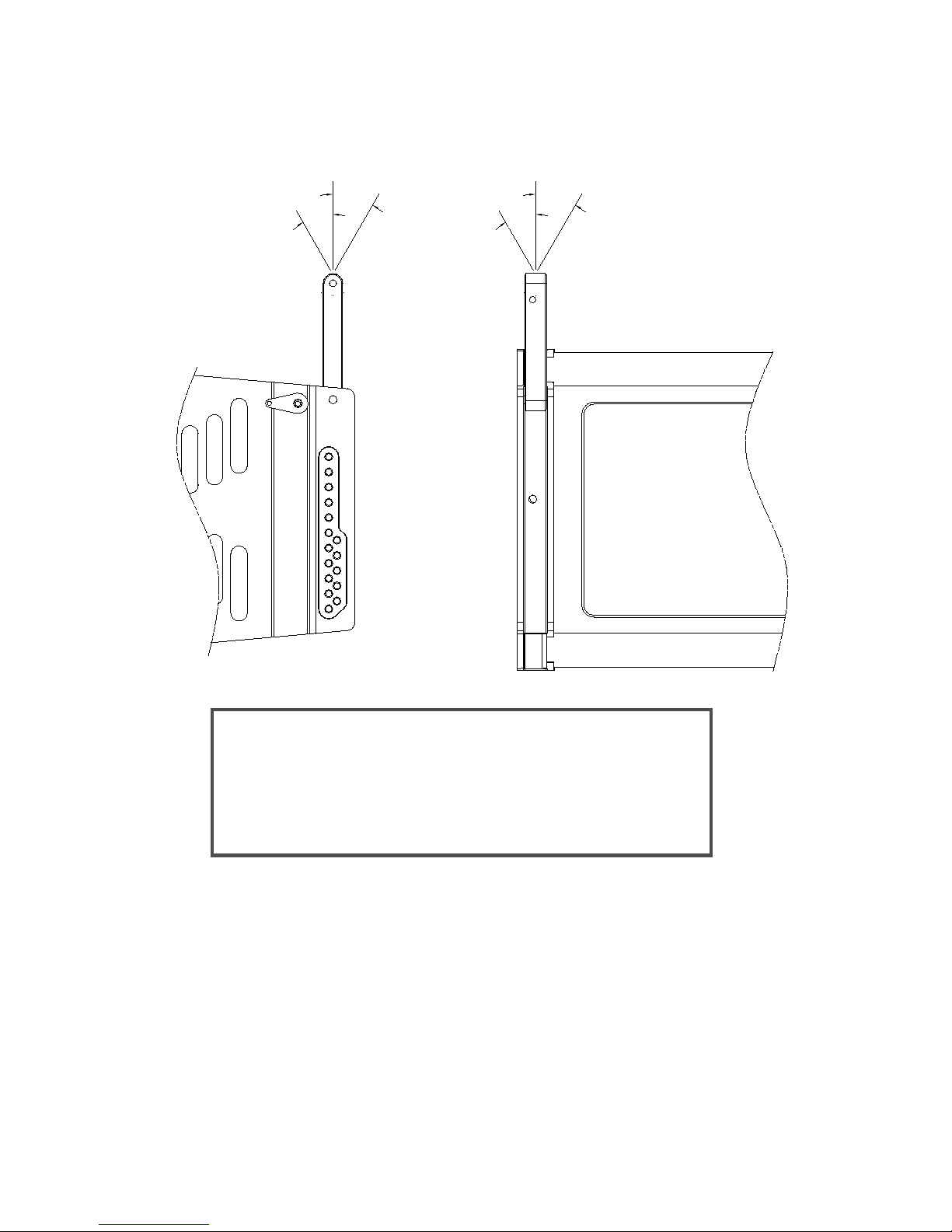
and the angle of pull. The structural-strength ratings for the rear rigging points are identical for the
XLD281, XLE181, and XS212, and are shown in Figure 10. The enclosures have two rigging
points at the rear. The structural ratings shown in Figure 10 are for a single rigging attachment
point. Each rigging point has the same rating.
It should be noted that the front-to-back-angle range shown in Figure 10 for the XLD281 and
XLE181 consists of two 10° arc segments, while the front-to-back-angle range shown in Figure 10
for the XS212 consists of two 20° arc segments. When both the front and rear rigging are
installed, the front hinge bar always prevents the rear swing arm from having any kind of front-toback force. Thus, it will always be axially loaded. For the XLD281 and XLE181, a tensile force can
only be applied over an angle range of negative 0°-10°, while the XS212 can only be over a range
of negative 0°-20°. The angles are negative because the boxes can only be angled downward.
(Imagine two boxes facing straight ahead. The bottom enclosure can only be tilted downward
because the rear rigging can only be adjusted to bring the rear corners of the enclosures
together). It also should be noted that the XLVC rear rigging is only rated for use over side-to-side
pull angles of a maximum of ±5°.
ELECTRO-VOICE® X-Line Very CompactTM Rigging Manual21
Page 23
+5°
MAX
-5°
MAX
-∅°
+∅°
Specifications
XLD281, XLE181, and XS212 Front-Rigging-Point
ELECTRO-VOICE® X-Line Very CompactTM Rigging Manual 22
Pending
Figure 9:
Structural Ratings
Page 24
+∅°
-∅°
-5°
MAX
+5°
MAX
Working-Load Limit
850 lb (386 kg)
From 0° to -10° (XLD281, XLE181 - Swing Arm in Tension)
From 0° to -20° (XS212 - Swing Arm in Tension)
From +170° to +180° (XLD281, XLE181 - Swing Arm in Compression)
From +160° to +180° (XS212 - Swing Arm in Compression)
These are the Only Possible Angle Ranges
Figure 10:
XLD281, XLE181, and XS212 Rear-Rigging-Point
Structural Ratings
ELECTRO-VOICE® X-Line Very CompactTM Rigging Manual23
Page 25
Total Column Weight
Working-Load Limit
850 lb (386 kg)
Figure 11:
XLD281, XLE181 and XS212 Overall
Enclosure Structural Ratings
ELECTRO-VOICE® X-Line Very CompactTM Rigging Manual
24
Page 26

XLD281, XLE181, and XS212 Overall Enclosure Structural-Strength Ratings
The actual strength of the XLVC enclosures will depend on the complex total of the combined
forces from each of the rigging points acting on the enclosure as a whole and will vary with the
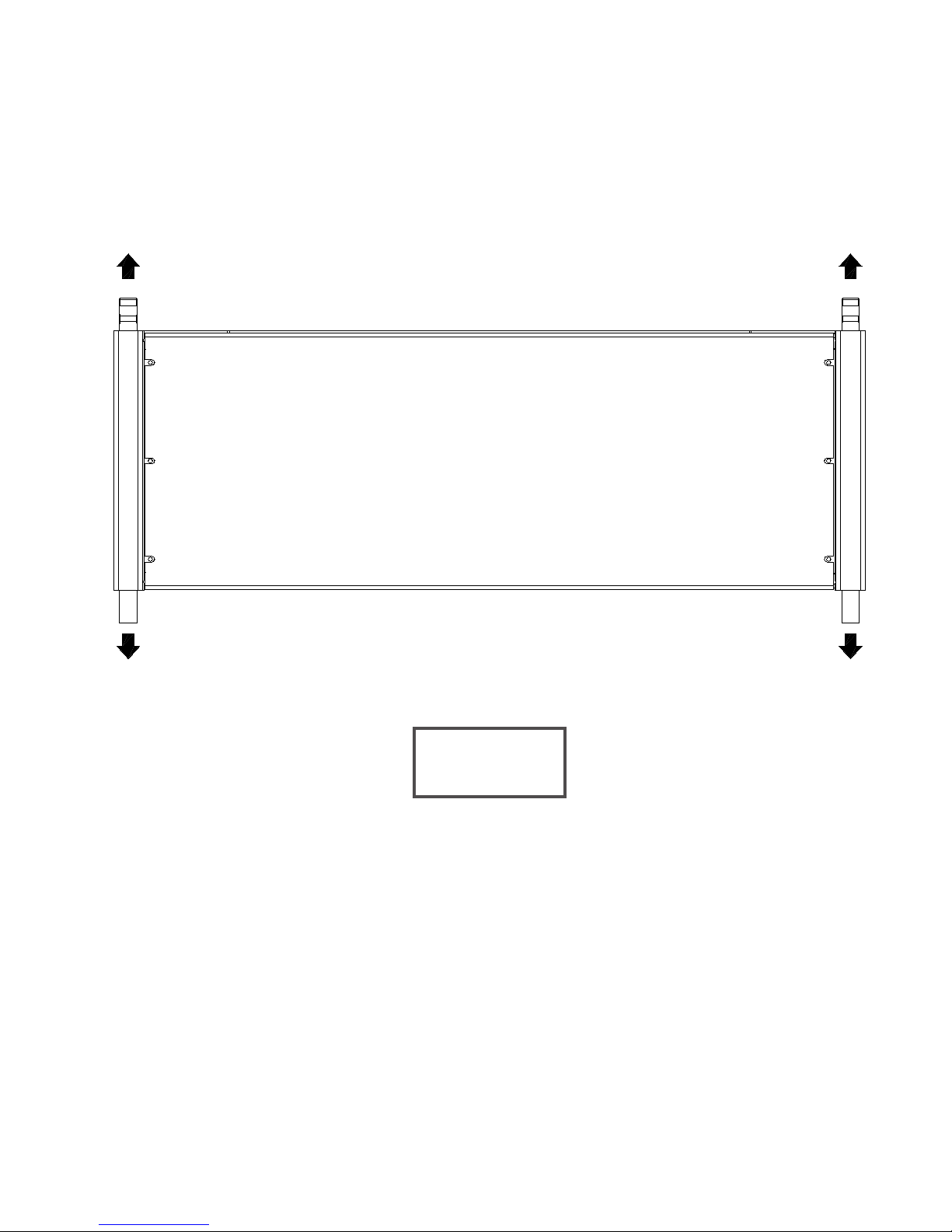
array configuration. However, for the sake of simplicity, Electro-Voice chooses to define the working-load limit of the overall enclosures as the sum total of the weight of that enclosure plus the
weight of all of the enclosures and rigging hardware suspended below. This simplified workingload weight rating of the overall enclosures is defined as being independent of the angles of pull
on the individual rigging points. The Electro-Voice engineers have chosen to define the workingload limits of the individual rigging points as a function of pull angle so that they take into account
any variations in enclosure strength that might occur as a function of pull angle. This approach
allows the enclosure working-load limit to be defined as independent of pull angles, making the
complex structural rating analysis easier. The overall enclosure strength ratings are identical for
the XLD281, XLE181, and XS212, and are shown in Figure 11.
CAUTIONS for a Complex Structural Rating Analysis
WHEN APPL YING A COMPLEX STRUCTURAL RATING ANALYSIS TO ANY
XLVC LOUDSPEAKER SYSTEM SUSPENDED OVERHEAD, THE USER MUST
OBEY THE FOLLOWING RULES:
1. Never exceed the front-to-back angle limits for the front hinge-bar assemblies on any
enclosure. Never exceed the side-to-side angle limits for the front hinge-bar assemblies on
any enclosure.
2. Never exceed the front-to-back angle limits for the rear swing-arm assemblies on any
enclosure. Never exceed the side-to-side angle limits for the front swing-arm assemblies on
any enclosure.
3. Always make sure that every front button bar is securely locked in the front rigging tube on
every enclosure (and grid, when applicable) before lifting overhead.
4. Always make sure that every rear swing arm is securely locked in the rear rigging channel
with the quick-release pins on every enclosure (and grid, when applicable) before lifting
overhead.
3.5 Wind Loading
The XLVC loudspeaker systems have been designed to withstand winds of up to 60 miles per
hour (96.6 kilometers per hour) if the bottom cabinet is rigidly secured. For obvious safety
reasons, Electro-Voice urges the user not to suspend any loudspeaker systems overhead
outdoors when high winds are expected. When suspending XLVC loudspeaker systems outdoors,
the user is strongly encouraged to rigidly tie off the bottom cabinets in all arrays as a safety
precaution against unexpected high winds.
A pull-up grid with an attached strap may be used to secure the bottom cabinets. The tie-off
assembly must have a working-load rating of 2,000 lb (907 kg). A ratchet strap with a 2,000-lb
working-load rating must be used for the pull-up assembly.
ELECTRO-VOICE® X-Line Very CompactTM Rigging Manual25
Page 27

3.6 Electro-Voice Structural-Analysis Procedures
Electro-Voice maintains a structural pull-test facility in Burnsville, Minnesota USA which includes
load cells with digital-electronic display and recording. The load cells are calibrated annually by an
independent laboratory to a standard traceable to the United States National Bureau of Standards.
This pull-test facility is capable of pulling to destruction both individual rigging components and
complete loudspeaker systems.
Electro-Voice utilizes state-of-the-art computer-modeling programs for structural analysis throughout the development of loudspeaker systems. The computer modeling enables the complex forces
in the rigging components and enclosures to be analyzed for loudspeakers assembled into arrays
in both static and dynamic conditions.
Structural testing and computer modeling were used throughout the engineering development of
all the XLVC individual rigging components and complete loudspeaker systems described in this
manual. Testing and modeling involving both anticipated use and anticipated misuse were performed as part of the analysis. Engineering prototypes were stressed to failure and designs were
revised based on those test results. Production systems and components were stressed to failure
for verification of the final designs.
ELECTRO-VOICE® X-Line Very CompactTM Rigging Manual 26
Page 28

4. Rigging Inspection and Precautions
Electro-Voice XLVC Loudspeaker Systems:
Prior to each use, inspect the loudspeaker enclosures for any cracks, deformations, missing or
damaged components that could reduce enclosure strength. Inspect the rigging tube and channel
assemblies on the enclosures for any cracks, deformations, corrosion, missing or loose screws
which could reduce the flying hardware strength. Replace any loudspeaker systems that are
damaged or missing hardware. Never exceed the limitations or maximum recommended load for
the XLVC systems.
Electro-Voice XLVC Front Rigging Hinge Bar Assemblies: Prior to each use, inspect the front
rigging hinge bars and the front rigging tubes for any cracks, burrs, deformations, corrosion or
missing or damaged components that could reduce hinge bar assembly strength. Always check to
make sure that the hinge bar can move freely in the front rigging tube. Replace any hinge bars
that are damaged or missing hardware. Always double check that each quick-release pin on each
hinge bar is securely locked into position in the front rigging tubes on the XLVC enclosures and
grids before lifting. Never exceed the limitations or maximum recommended load for the XLVC
rigging hardware.
Electro-Voice XLVC Rear Swing Arm Assemblies: Prior to each use, inspect the rear rigging
swing arms, the rear rigging channels and rear rigging holes for any cracks, burrs, deformations,
corrosion or missing or damaged components that could reduce swing arm assembly strength.
Always check to make sure that the swing arm bar can move freely in the rear rigging slots and
that the quick-release locking pins can be easily inserted in the swing arm holes and rigging holes
to lock the arm. Replace any swing arms that are damaged or missing hardware. Always double
check that each swing arm is securely locked in the rear rigging holes with a quick-release pin.
Never exceed the limitations or maximum recommended load for the XLVC rigging hardware.
Electro-Voice Quick-Release Pins: Prior to each use, inspect the quick-release pins on the
rigging frame assemblies any for cracks, burrs, deformations, corrosion or missing or damaged
components that could reduce the pin strength. Replace any quick-release pins that are
damaged. Always double check that each quick-release pin is securely locked to the front hinge
bar and rear swing arm assemblies on the XLVC enclosures before lifting. Never exceed the
limitations or maximum recommended load for the XLVC rigging hardware.
Grid Assemblies: Prior to each use, inspect each grid assembly any for cracks, burrs,
deformations, corrosion or missing or damaged components that could reduce the grid assembly
strength. Replace any grids that are damaged or missing hardware. Always double check that
each grid is securely locked to the front hinge bar assemblies and the rear swing arm assemblies
on the XLVC enclosures before lifting. Always double check that each quick-release pin attaching
the sidearms to the spreader bar(s) are securely locked into place. Never exceed the limitations
or maximum recommended load for the grids.
ELECTRO-VOICE® X-Line Very CompactTM Rigging Manual27
Page 29

Coupler Beam (CBeam) Assemblies: Prior to each use, inspect the CBeam assemblies for any
cracks, burrs, deformations, corrosion or missing or damaged components that could reduce the
CBeam assembly strength. Replace any CBeam assemblies that are damaged or missing
hardware. Always double check that each CBeam assembly is securely locked to the spreader
bar(s) on the grids below. Never exceed the limitations or maximum recommended load for the
CBeam assemblies.
Chain Hoists: Prior to each use, inspect the chain hoist and associated hardware (including
motor, if applicable) for any cracks, deformation. Broken welds, corrosion, missing or damaged
components that could reduce the hoist strength. Replace any damaged chain hoists. Never
exceed the limitations or maximum recommended load specified by the hoist manufacturer.
Always follow manufacturers’ recommendations for operation, inspection, and certification. Always
raise and lower the load slowly and evenly, avoiding any rapid changes in speed or shifting loads
that could result in a sudden jolt to the suspended system.
Building, Tower or Scaffold Supports: Prior to each use, the strength and load-bearing
capabilities of the building, tower or scaffold structural supports should be evaluated and certified
by a professional engineer as being adequate for supporting the intended rigging system
(including the loudspeakers, grids, chain hoists and all associated hardware). Prior to each use,
inspect the building, tower or scaffold structural supports for any cracks, deformation, broken
welds, corrosion, missing or damaged components that could reduce the structural strength.
Damaged structural supports should be replaced or repaired and recertified by a professional
engineer. Never exceed the limitations or maximum recommended load for the supports.
Miscellaneous Mechanical Components: Prior to each use, inspect all mechanical components
(chain, wire ropes, slings, shackles, hooks, fittings, ratchet straps, etc.) for any cracks,
deformation, broken welds, slipping crimps, fraying, abrasion, knots, corrosion, chemical damage,
loose screws, missing or damaged components that could reduce the maximum strength specified
by the component manufacturer. Replace any damaged mechanical components. Never exceed
the limitations or maximum recommended load for the mechanical components.
ELECTRO-VOICE® X-Line Very CompactTM Rigging Manual
28
Page 30

References
Rigging References
[1] W.E. Rossnagel, L.R. Higgins & J.A. MacDonald, Handbook of Rigging for Construction and
Industrial Operations, McGraw-Hill Book Company, New York, NY, USA (1988).
[2] J.O. Glerum, Stage Rigging Handbook, Southern Illinois University Press, Carbondale, IL, USA
(1987).
[3] P. Carter, Backstage Handbook, Broadway Press, New York, NY, USA (1988).
[4] ATM Fly-Ware™, Riggermeister Production Rigging Guide, ATM Fly-Ware™, Carson, CA,
USA (1995).
[5] Wire Rope Technical Board, Wire Rope Users Manual, American Iron and Steel Institute,
Stevensville, MD, USA (1985).
[6] Broderick & Bascom Rope Company, Rigger’s Handbook, Sedalia, MO, USA (1993).
[7] MacWhite Wire Rope Company, Catalog of Tables, Data and Helpful Information, Kenosha,
WI, USA (1991).
[8] Acco Chain & Lifting Division, Chain Sling User’s Manual, Acco Corporation, York, PA, USA
(1992).
[9] Newberry, W.G., Handbook for Riggers, Newberry Investments Company, Calgary, Alberta,
Canada (1989).
Mechanical Engineering References
[10] J.L. Meriam & L.G. Kraige, Engineering Mechanics, Volume One - Statics, John Wiley &
Sons, Inc., New York, NY, USA (1992).
[11] J.L. Meriam & L.G. Kraige, Engineering Mechanics, Volume Two - Dynamics, John Wiley &
Sons, Inc., New York, NY, USA (1992).
[12] J.E. Shigley & C.R. Mischke, Mechanical Engineering Design, McGraw-Hill Book Company,
New York, NY, USA (1989).
[13] A. Jensen & H.H. Chenoweth, Applied Engineering Mechanics, McGraw-Hill Book Com-pany,
New York, NY, USA (1983).
Websites
[14] http://www.cmworks.com/
[15] http://catalog.thecrosbygroup.com/maininterface.htm
ELECTRO-VOICE® X-Line Very CompactTM Rigging Manual29
Page 31

Notes
ELECTRO-VOICE® X-Line Very CompactTM Rigging Manual
30
Page 32

U.S.A. and Canada:
For customer orders, contact the Customer Service department at:
800/392-3497 Fax: 800/955-6831
For warranty repair or service information, contact the Service Repair Department at:
800/685-2606
For technical assistance, contact Technical Support at:
866/78-AUDIO
Specifications subject to change without notice.
All Other International Locations:
952-884-4051 Fax: 952-736-4212
www.electrovoice.com
Printed in U.S.A
© Telex Communications, Inc. 2/2005
Part Number 38110-429 Rev 1
Telex Communications, Inc.
ELECTRO-VOICE® X-Line Very CompactTM Rigging Manual
www.telex.com
 Loading...