

Page 1

Xw12
X-ArrayTM Two-Way,
Full-Range Floor Monitor
• New 12-inch woofer design
provides improved internal
damping of cone
• New DH6, 1.4-inch compression
driver
• Rugged 12-ply ultracompact,
uniquely curved enclosure
• Constant-directivity 80° x 55° horn
• Professional Neutrik Speakon
paralleled pass-through connectors
on both ends of enclosure
®
Description
The Electro-Voice Xw12 full-range, twoway, floor monitor loudspeaker system is part
of the Electro-Voice X-Array
intended for high-level sound reinforcement
in fixed-installation and touring-sound
applications. The Xw12 is a full-range
biamped floor monitor speaker system which
may be used with the Electro-Voice Dx38
digital crossover, the Klark Teknik DN8000
or any high-quality, signal-controller system.
The Xw12 employs a custom-designed, 12inch woofer for low-frequency reproduction. Designed as part of the Xw12 development, this woofer uses a new cone material to provide maximum internal damping.
This woofer also employs "DL" technology
which utilizes a Thermal Inductive Ring, (TIR
a nonmagnetic pole piece extension that controls inductance and, most importantly, provides a major heat transfer path from the top
of the voice coil to minimize power compression. For high frequencies, the Xw12 uses the
DH6, a 1.4-inch-exit variant of the DH1A compression driver designed as part of the Xw12
development. Its unique one-piece geometrically optimized titanium dome and suspension combined with its unusually powerful
magnetic motor provide maximum efficiency
and precise control of the diaphragm mo-
™
series and is
™
tion. The compression driver is coupled
to an 80º x 55º horn. This flat-front, constantdirectivity horn is based on the Electro-Voice
HP series, and is geometrically optimized for
performance from 1,250-20,000 Hz.
The XW12 is constructed of 18-mm voidfree, 3/4-inch 12-ply curved plywood shell
which is extremely rigid. The baffle and end
pieces are made from 18-mm 13-ply birch
plywood. This high-strength enclosure
is sprayed with a resilient, textured black
finish for a truly professional appearance.
The end-mounted, recessed handle makes
transportation relatively easy.
Applications
The XW12 loudspeaker system is ideal for
use as a professional stage touring or installation application floor monitor where ex-
),
tremely high power and low distortion, as
well as accurate vocal coverage and maximized intelligibility are required from a system housed in a compact, low-profile enclosure. Its symmetrical design will allow two
monitors to be placed head to head so that
the high-frequency horns are coupled for
high-level large stage applications. The
Xw12 and associated controller combinations are recommended for applications requiring full bandwidth down to 60 Hz.
Power-Handling T est
Electro-Voice components and systems are
manufactured to exacting standards to ensure reliability in continuous use in arduous
real-life conditions. Besides utilizing industry-standard power tests, extreme in-house
power tests which push the performance
boundaries of the loudspeakers are also performed for an extra measure of reliability.
The XW12 systems are rated per ANSI/
EIA RS-426-A Loudspeaker Power Rating,
Full Range Test, which uses a shaped-random-noise signal to simulate typical music
to test the mechanical and thermal capabilities of the loudspeakers. The Dx38 digital electronic unit was used to provide the
necessary crossover filters and equalization during power testing. Specifically, the
Xw12 passes the ANSI/EIA RS-426-A
power test with the following test parameters:
Low-Frequency Section:
P
: 300 watts
E(MAX)
Test Voltages: 47.0-volts rms
94.0-volts peak
R
(1.15 RE): 7.36 ohms
SR
High-Frequency Section:
: 75 watts
P
E(MAX)
Test Voltages: 28.0-volts rms
54.0-volts peak
(1.15 RE): 10.5 ohms
R
SR
Page 2

Xw12 T wo-W ay, Full-Range Floor Monitor
Crossover , Equalization and Time-Delay
Controller
The Xw12 speaker system was designed
as an integrated package that utilizes
the Electro-Voice Dx38 digital crossover
system.
The Dx38 features a 125-Hz crossover frequency utilizing 24-dB-per-octave
Linkwitz-Riley filters, and contains time
delay and equalization for optimum performance of the Xw12.
Electrical Connection and System
Wiring
Electrical connections to the Xw12 are
made on the sides of the enclosure via parallel pass through 4-pin connectors. There
are two connectors on each of the input
Xw12 Two-Way, Full-Range Floor Monitor
panels to allow paralleling of other Xw12
systems. The Neutrik Speakon
®
NL4MPR
is used for both connections. The pin assignments are as follows:
Pin 1+: LF(+)
Pin 1-: LF(–)
Pin 2+: HF(+)
Pin 2-: HF(–)
The wiring diagram of the loudspeaker
system is shown in Figure 7. The electrical
impedance is shown in Figure 6.
Amplifier Requirements
Power amplifiers with the following ratings
are recommended for use with the Xw12
speaker systems:
LF: 600 watts per channel into 8 ohms.
HF: 600 watts per channel into 8 ohms.
Xw12 speakers may be paralleled only with
other Xw12 speakers if the amplifier is capable of delivering full power at the lower
impedances. The use of amplifiers with
lower power ratings is acceptable; however, the full-power capabilities of the Xw12
speakers will not be realized. The use of
amplifiers with significantly higher power
ratings will generate maximum dynamic
range and fidelity, but care must be utilized for longer duration signals as mechanical and thermal damage are possible in the
system. Under certain circumstances, higher
rated amplifiers are acceptable. It is acceptable to drive the Xw12 speakers with a stereo power amp utilizing one channel to drive
2
the low frequencies and the other channel
to drive the high frequencies.
Field Replacement
The Xw12 may be serviced in the following
ways. Remove the grille to allow access to
both the woofer and high-frequency driver.
Remove the woofer bolts to allow the woofer
to easily be removed for repair or replacement.
In case of a compression driver failure, a diaphragm assembly replacement kit is available.
T o remove the compression driver, remove the
horn-mounting screws. Remove the woofer
to gain access to the compression driver. Remove the two accessable hex socket screws
attaching the horn to the driver through the
woofer cut-out opening. After removing the
screws, lift the high-frequency horn and rotate 180 degrees allowing access to remove
the remaining screws. Remove the compression driver through the woofer cut-out opening. If desired, the complete driver may be returned for service.
The following replacement parts are available from EVI Audio Service in Buchanan,
Michigan:
LF: Complete woofer: EV Part No. 812-2997
HF: Diaphragm kit: EV Part No. 84233-XX
Architects' And Engineers'
Specifications
The loudspeaker speaker system shall be a
two-way biamped system with performance
controlled by a variety of dedicated electronic
control units. The loudspeaker system shall
have a 305-mm (12-inch) direct-radiating
driver with an 8-ohm, 63.5-mm (2.5-inch)
voice coil constructed of aluminum wire, and
shall be capable of a 300-watt shaped pinknoise signal with a 6-dB crest factor for eight
hours (as per ANSI/EIA RS-426-A 1980).
The loudspeaker system shall have a 35.6-mm
(1.4-inch) exit compression driver mounted on
a high-frequency horn. The compression
driver shall have 76.2-mm (3.0-inch) diameter, titanium dome and a 16-ohm nominal,
76.2-mm (3.0-inch) di ameter voice coil constructed of aluminum wire, and shall be capable of handling a 75-watt, 1,600- 20,000Hz pink-noise signal with a 6-dB crest factor
for eight hours (as per ANSI/EIA RS-426-A
1980 standard). The high-frequency horn shall
be of the constant-directivity type and shall
produce a nominal horizontal beamwidth
(6-dB-down angle) of 80° from 2,000-20,000
Hz and a nominal vertical beamwidth of 55°
from 1,600-20,000 Hz. The loudspeaker
system enclosure shall be constructed of 18-mm
thick, 12-ply flat birch plywood and .75-inch
thick, 12-ply curved birch plywood, covered
with black textured paint and shall have a
14-gauge perforated steel grille.
When used with the electronic control unit,
the loudspeaker system shall have a flat onaxis frequency response from 60 -16,000 Hz.
The loudspeaker enclosure dimensions
shall be 358.3 mm (14.11 in.) high, 584.2 mm
(23.00 in.) wide and 408.8 mm (16.10 in.) deep
and shall weigh 28.2 kg (62 lb).
The loudspeaker shall be the Electro-Voice
Xw12 .
Uniform Limited Warranty
Electro-Voice products are guaranteed
against malfunction due to defects in materials or workmanship for a specified period,
as noted in the individual product-line
statement(s) below, or in the individual product data sheet or owner’s manual, beginning
with the date of original purchase. If such
malfunction occurs during the specified period, the product will be repaired or replaced
(at our option) without charge. The product
will be returned to the customer prepaid.
Exclusions and Limitations: The Limited
W arranty does not apply to: (a) exterior finish or appearance; (b) certain specific items
described in the individual product-line
statement(s) below, or in the individual product data sheet or owner’s manual; (c) malfunction resulting from use or operation of
the product other than as specified in the
product data sheet or owner’s manual; (d)
malfunction resulting from misuse or abuse
of the product; or (e) malfunction occurring
at any time after repairs have been made
to the product by anyone other than
Electro-Voice Service or any of its authorized service representatives. Obtaining
Warranty Service: To obtain warranty service, a customer must deliver the product,
prepaid, to Electro-Voice Service or any of
its authorized service representatives together with proof of purchase of the product in the form of a bill of sale or receipted
invoice. A list of authorized service repre-
Page 3
Xw12 T wo-W ay, Full-Range Floor Monitor
sentatives is available from Electro-Voice
Service at 600 Cecil Street, Buchanan, MI
49107 (800-234-6831 or FAX 616-695-4743).
Incidental and Consequential Damages Excluded: Product repair or replacement and
return to the customer are the only remedies
provided to the customer. Electro-Voice shall
not be liable for any incidental or consequential damages including, without limitation, injury to persons or property or loss of
use. Some states do not allow the exclusion
or limitation of incidental or consequential
damages so the above limitation or exclusion may not apply to you. Other Rights:
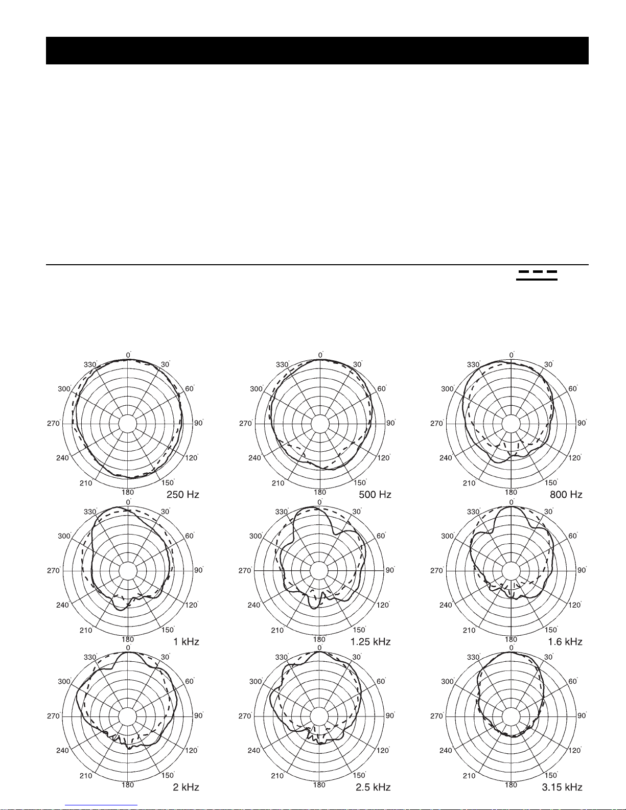
Figure 1—Polar Response (5 dB per division)
This warranty gives you specific legal rights,
and you may also have other rights which
vary from state to state.
Electro-Voice Speakers and Speaker Systems are guaranteed against malfunction due
to defects in materials or workmanship for a
period of five (5) years from the date of original purchase. The Limited W arranty does not
apply to burned voice coils or malfunctions
such as cone and/or coil damage resulting from
improperly designed enclosures. Electro-V oice
active electronics associated with the speaker
systems are guaranteed for three (3) years from
the date of original purchase. Additional de-
tails are included in the Uniform Limited
W arranty statement.
Electro-Voice Accessories are guaranteed
against malfunction due to defects in materials or workmanship for a period of one (1)
year from the date of original purchase. Additional details are included in the Uniform Limited W arranty statement.
For warranty repair, service information, or a
listing of the repair facilities nearest you,
contact the service repair department at:
616/695-6831 or 800/685-2606.
For technical assistance, call: 800/234-6831.
Specifications subject to change without notice.
Vertical
Horizontal
The directional response of the system was measured in an anechoic environment at a distance of 6.1 m (22 ft) using 1/3-octave -filtered pink
noise with a full spherical measurement system. The Dx38 digital electronic unit was used to provide the necessary crossover filters,
equalization and time delay. The polar response of the loudspeaker system at selected 1/3-octave frequencies is shown. The selected frequencies are representative of the polar response of the system.
Xw12 Two-Way, Full-Range Floor Monitor
3
Page 4
Xw12 Two-Way, Full-Range Floor Monitor
Xw12 T wo-W ay, Full-Range Floor Monitor
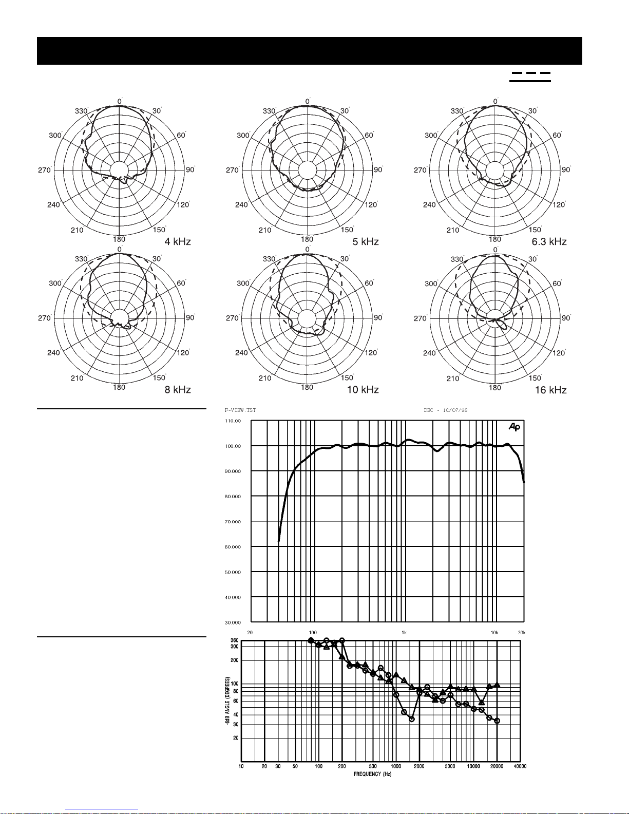
Vertical
Horizontal
5 dB per division
XW12 Two-Way, Full-Range Floor Monitor
Figure 2—Frequency Response
The frequency response of the system was
measured on axis in the farfield in an
anechoic environment using a swept sinewave signal. The Dx38 digital electronic
unit was used to provide the necessary
crossover filters, equalization and time
delay. One watt of power (2.83 volts rms
at 400 Hz) was applied to the midband of
the low-frequency section. The soundpressure level was normalized for an
equivalent one meter distance.
Figure 3—Beamwidth
The beamwidth of the system, (i.e., the included horizontal and vertical coverage
angles at the 6-dB-down point) was measured with a full spherical measurement
system as described in "Polar Response."
4
Page 5
Xw12 T wo-W ay, Full-Range Floor Monitor
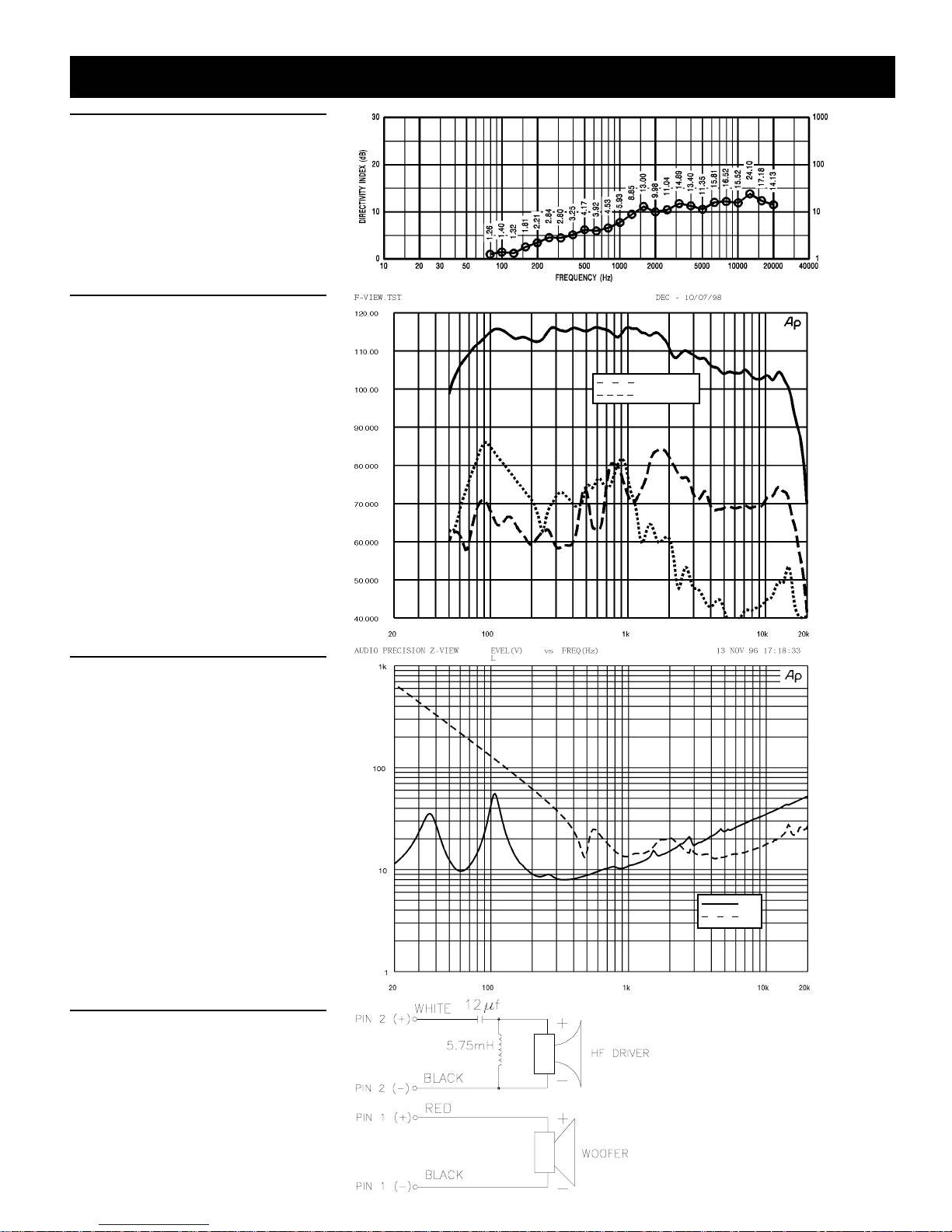
Figure 4—Directivity
The directivity index, D
factor R
(Q), of the system were measured
θ
, and directivity
i
with a full spherical measurement system
as described for the "Polar Response."
Figure 5—Distortion
Distortion for the system was measured
on axis in the farfield in an anechoic environment with an input signal that would
result in a sound-pressure level of 115 dB
at one meter. The Dx38 digital electronic
unit was used to provide the necessary
crossover filters, equalization and time delay. A frequency spectrum typical of closemiked rock music was employed. The
sound-pressure level was normalized for
an equivalent one-meter distance. Plots of
second and third harmonic distortion are
shown referenced to the fundamental.
2nd Harmonic
3rd Harmonic
DIRECTIVITY FA CT OR R
q
Q
Xw12 Two-Way, Full-Range Floor Monitor
Figure 6—Impedance
The impedance of each frequency band of
the system was measured in an anechoic
environment.
Figure 7—Wiring
The wiring diagram of each frequency band
of the system is shown.
LF
HF
5
Page 6
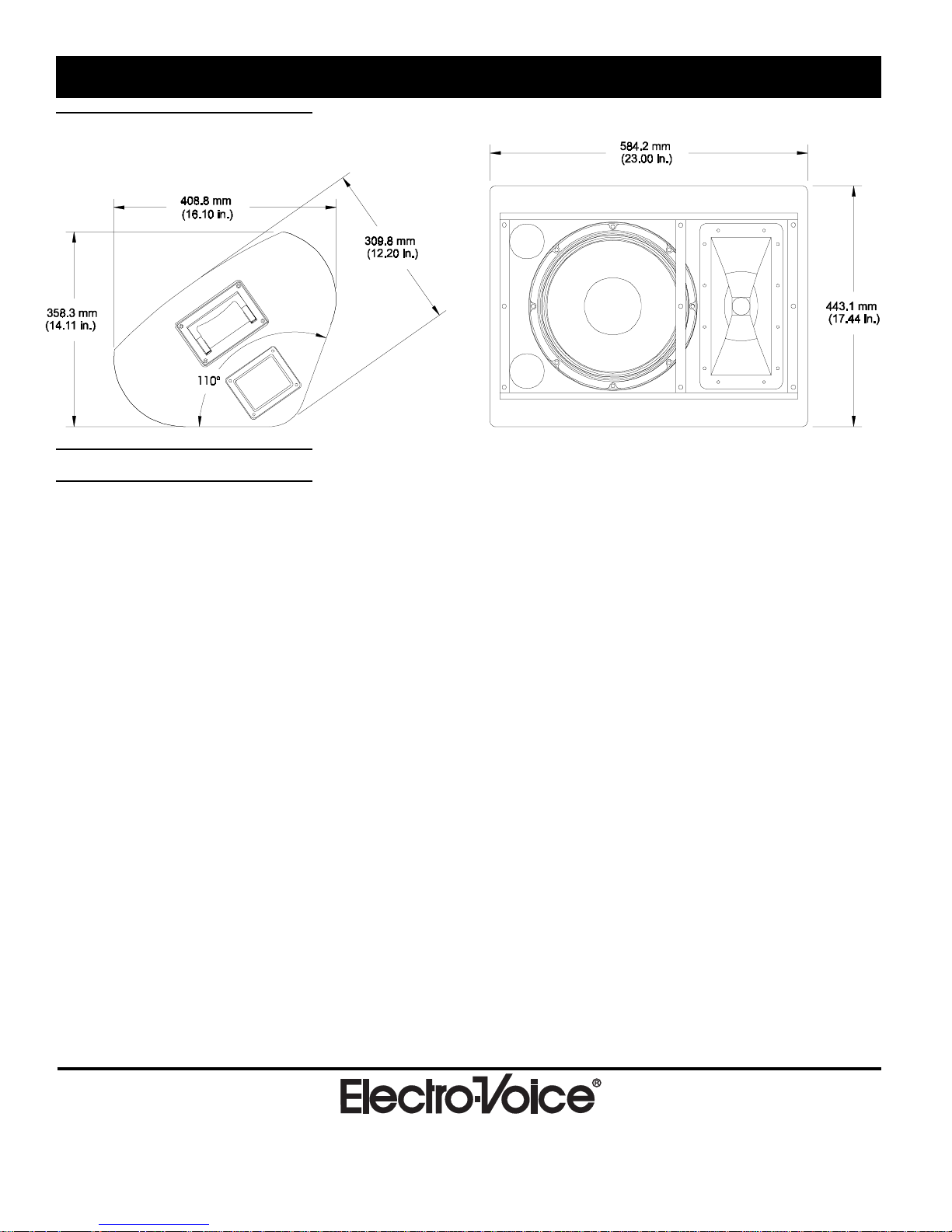
Figure 8—Dimensions
Xw12 T wo-W ay, Full-Range Floor Monitor
Specifications
Xw12 Two-Way, Full-Range Floor Monitor
Frequency Response (measured in far
field, calculated to one meter on axis,
swept sine wave, one watt into LF
section 2.83 V at 400 Hz, anechoic
environment; see Figure 2):
60-16,000 Hz
Crossover Frequency:
1,250 Hz
Efficiency, LF/HF:
4.8/25 %
Maximum Long-Term-Average PowerHandling Capacity (per ANSI/EIA RS426A 1980), LF/HF:
300/75 watts
Maximum Long-Term-Average
Midband Acoustic Output, LF/HF:
14/18.8 acoustic watts
Sensitivity (SPL at one meter, indicated
input power, anechoic environment,
average level), LF/HF,
1/1 watt:
99.0/110.0 dB
300/75 watts:
124.0/129.0 dB
Beamwidth (angle included by 6-dBdown points on polar responses,
indicated one-third-octave bands of pink
noise; see Figures 1 and 3),
Horizontal, 1,200-16,000 Hz:
80° (+25°, -20°)
Vertical, 1,200-16,000 Hz:
55° (+25°, -20°)
Directivity Factor, R
Hz Average (see Figure 4):
(Q), 1,200-16,000
θ θ
θ
θ θ
14.3 (+9.8, -5.4)
Directivity Index, D
Average (see Figure 4):
, 1,200-16,000 Hz
i
11.6 dB (+2.3 dB, -2.1 dB)
Distortion (115 dB SPL at one meter,
shaped spectrum; see Figure 5),
Second Harmonic,
100 Hz:
0.5 %
500 Hz:
0.8 %
2,000 Hz:
3.7 %
5,000 Hz:
1.7 %
Third Harmonic,
100 Hz:
3.3 %
500 Hz:
0.9 %
2,000 Hz:
0.3 %
5,000 Hz:
<0.1 %
T ransducer Complement,
HF:
DH6 driver, HP-type 80°x 55° horn
LF:
DL-type 12-in. woofer
Impedance (see Figure 6),
Nominal, LF/HF:
8/16 ohms
Minimum, LF/HF:
8.2/10.5 ohms
Input Connections:
Two Neutrik NL4MPR Speakon
connectors paralleled on each side of
enclosure
Recommended Amplifier Power,
HF:
600 watts per channel @ 8 ohms
LF:
800 watts per channel @ 8 ohms
Enclosure Construction,
Enclosure Shell:
3/4-in., 12-ply curved birch plywood
18-mm, 13-ply flat birch plywood
Finish:
Black textured paint
Grille:
14-gauge perforated steel
Dimensions,
Height (front):
443.1 mm (17.44 in.)
Height (profile):
358.3 mm (14.11 in.)
Width:
584.2 mm (23.00 in.)
Depth (overall):
309.8 mm (12.20 in.)
Depth (profile):
408.8 mm (16.10 in.)
Angle:
110° wedge
Net Weight:
28.2 kg (62 lb)
Shipping Weight:
31.3 kg (69 lb)
®
TM
6
600 Cecil Street, Buchanan, MI 49107
616/695-6831, 616/695-1304 Fax
©Telex Communications, Inc., 1999 • Litho in U.S.A.
Part Number 534226 Rev. B—9934SPEAKERS—X-Array
 Loading...