

Electro-Voice X1-212/90, X12-128, X12TE-GRID, X2-212/90, X12T-DOLLY Installation Manual
...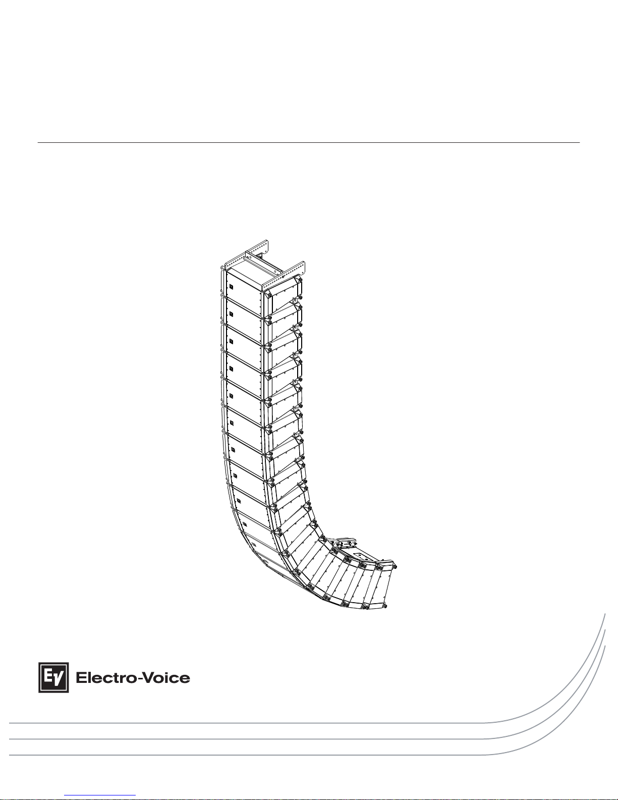
X-LINE ADVANCE Systems
X1-212/90, X12-128, X2-212/90, X12TC-GRID, X12TE-GRID, X12PU-BGK, X12T-DOLLY, and
X12-128-DOLLY
en | Installation Manual


Table of contents
1
Safety 5
1.1 Important Safety Instructions 6
1.2 Precautions 6
1.3 Suspension 6
2
Introduction 7
3
System overview 8
3.1 Dimensions 9
3.1.1 Accessories dimensions 10
4
Designing an X1 or X2 array 13
4.1 Applications for which X-Line Advance arrays are most appropriate 13
4.2 Determining X1 and X2 array configuration with LAPS 3 13
5
Preparing X-Line Advance elements for installation 14
5.1 Recommended preflight procedures 14
5.2 Element configuration 14
6
Rigging system 15
6.1 Overview of the flying system 15
6.2 Rigging the boxes together 15
6.3 Setting rear link angles 17
6.4 Deciding which grid configuration to use 20
6.4.1 X12TC-GRID compact grid 20
6.4.2 X12TE-GRID extended grid 23
6.4.3 X12PU-BGK pull-up kit 28
6.5 X12T-DOLLY and X12-128-DOLLY 31
6.5.1 Stacking X1 & X2 loudspeakers onto a X12T-DOLLY 32
6.5.2 Stacking X12-128 subwoofer(s) onto a X12-128-DOLLY 35
6.6 Assembling and flying an array 37
6.6.1 Flying arrays from the dolly 37
6.6.2 X12TC-GRID with pull-back to venue 41
6.6.3 X12TE-GRID using X12PU-BGK to pull-up to grid 43
6.6.4 Storing empty dollies 44
6.6.5 Landing arrays onto a dolly 45
6.7 Array building techniques 48
6.7.1 Multiple ways to fly the X12TC-GRID 48
6.7.2 Multiple ways to fly the X12TE-GRID 49
6.7.3 Array build strength considerations 50
7
Subwoofer arrays 52
7.1 Subwoofer array configuration 52
7.2 Subwoofer cardioid options 53
8
Rigging structural strength ratings and safety factors 54
8.1 Structural introduction 54
8.2 Structural rating overview 54
8.3 LAPS 3 structural evaluations simplified structural rating guidelines 55
8.4 Specific safety considerations 55
8.5 Working-load limit and safety factor definitions 56
en 3
Electro-Voice Installation Manual 2015.04 | 02 | F.01U.310.953

9
Rigging inspection and precautions 58
10
Technical data 59
11
References 62
11.1 Rigging (printed) 62
11.2 Mechanical engineering (printed) 62
11.3 Rigging (websites) 62
12
Notes 63
X-LINE ADVANCE Systems
2015.04 | 02 | F.01U.310.953 Installation Manual Electro-Voice

Safety
This document details general rigging practices appropriate to the entertainment industry, as
they would apply to the rigging of X1 and
X2 loudspeaker systems from Electro-Voice. It is
intended to familiarize the user with standard rigging hardware and techniques for suspending
X1 and X2 loudspeaker systems overhead. Only persons with the knowledge of proper
hardware and safe rigging techniques should attempt to suspend any sound systems
overhead. Prior to suspending any X1 and X2 loudspeaker systems overhead, it is essential the
user is familiar with the strength ratings, rigging techniques and special safety considerations
outlined in this manual. The rigging techniques and practices recommended in this manual
are, of necessity, in general terms to accommodate the many variations in loudspeaker arrays
and rigging configurations. As such, the user is expressly responsible for the safety of all
specific X1 and X2 loudspeaker array designs and rigging configurations as implemented in
practice.
All the general rigging material contained in this manual is based on the best available
engineering information concerning materials and practices, as commonly recognized in the
United States, and is believed to be accurate at the time of original printing. As such, the
information may not be directly applicable in other countries. Furthermore, the regulations
and requirements governing rigging hardware and practices may be superseded by local
regulations. It is the responsibility of the user to ensure any Electro-Voice loudspeaker system
is suspended overhead in accordance with all current federal, state, and local regulations.
All specific material concerning the strength ratings, rigging techniques, and safety
considerations for the X1 and X2 loudspeaker systems is based on the best available
engineering information concerning the use and limitations of the products. Electro-Voice
continually engages in testing, research and development of its loudspeaker products. As a
result, the specifications are subject to change without notice. It is the responsibility of the
user to ensure that any Electro-Voice loudspeaker system is suspended overhead in
accordance with the strength ratings, rigging techniques, and safety considerations given in
this document and any manual update notices. Visit our website: www.electrovoice.com for
current product technical documentation or software. All non-Electro-Voice associated
hardware items necessary to rig a complete X1 and X2 loudspeaker array (chain hoists,
building or tower supports, and miscellaneous mechanical components) are the responsibility
of others.
Electro-Voice
April 2015
1
en 5
Electro-Voice Installation Manual 2015.04 | 02 | F.01U.310.953
Important Safety Instructions
1. Read these instructions.
2.
Keep these instructions.
3. Heed all warnings.
4. Follow all instructions.
5. Clean only with a dry cloth.
6. Do not install near any heat sources such as radiators, heat registers, stoves, or other
apparatus (including amplifiers) that produce heat.
Old electrical and electronic appliances
Electrical or electronic devices that are no longer serviceable must be collected separately and
sent for environmentally compatible recycling (in accordance with the European Waste
Electrical and Electronic Equipment Directive).
To dispose of old electrical or electronic devices, you should use the return and collection
systems put in place in the country concerned.
Precautions
!
These Electro-Voice loudspeakers were designed for use in an environment with
ambient temperatures between -20°C (-4°F) and +50°C (122°F).
!
These Electro-Voice loudspeakers are not rated for continuous outdoor
conditions. However, they may be exposed to occasional short-term rain, water,
or high humidity.
!
Electro-Voice loudspeakers are easily capable of generating sound pressure
levels sufficient to cause permanent hearing damage to anyone within normal
coverage distance. Caution should be taken to avoid prolonged exposure to
sound pressure levels exceeding 90 dB.
Suspension
!
Warning!
Suspending any object is potentially dangerous and should only be attempted by individuals
who have a thorough knowledge of the techniques and regulations of suspending objects
overhead.
Electro-Voice
strongly recommends all loudspeakers be suspended taking into
account all current national, federal, state, and local laws and regulations. It is the
responsibility of the installer to ensure all loudspeakers are safely installed in accordance
with all such requirements. When loudspeakers are suspended, Electro-Voice strongly
recommends the system be inspected at least once per year or as laws and regulations
require. If any sign of weakness or damage is detected, remedial action should be taken
immediately. The user is responsible for making sure the wall, ceiling, or structure is capable
of supporting all objects suspended overhead. Any hardware used to suspend a loudspeaker
not associated with Electro-Voice is the responsibility of others.
1.1
1.2
1.3
X-LINE ADVANCE Systems
2015.04 | 02 | F.01U.310.953 Installation Manual Electro-Voice

Introduction
The X1 and X2
loudspeaker system line-array elements by Electro-Voice represent an
important step in line-array technology for small- to large-scale fixed-installation and live
sound reinforcement. The various models are designed to significantly simplify the physical
assembly of a line array. Also, X1 in passive mode may be designed so that up to three
elements are powered from one (1) amplifier channel, the necessary crossover and EQ
functions accomplished with sophisticated internal passive networks. X2 is designed to
operate in Bi-amp mode only. The individual loudspeaker drivers, Hydra planar-wave
generators, acoustic waveguides, enclosures and rigging hardware were all designed
specifically for the X1 and X2 product line to not only achieve the highest acoustic output with
the highest fidelity, but also produce a precise wave front from each element to achieve stateof-the-art line-array performance. The X12 subwoofer elements are designed to compliment
the performance of X1 and X2 full-range elements in applications where additional lowfrequency output is desired.
Although the X1 and X2 full-range elements are not physically symmetrical, their acoustic polar
responses are substantially symmetrical. Thus, stereo left and right arrays or left-center-right
arrays may be constructed with the elements in their normal right-side-up orientation.
2
en 7
Electro-Voice Installation Manual 2015.04 | 02 | F.01U.310.953

System overview
Each X1-212/90 full-range element consists of one (1) SMX2121 12-inch (304.8 mm) LF
drivers coupled to a MBH
(Mid Band Hydra) and two (2) ND2R 2-inch-diaphragms (50.8 mm)
HF drivers. Each HF driver is mounted on a WCH (Wavefront-shaping Circular Hydra)
planar-wave generator and vertically orientated.
X1 is designed in a two-way configuration with a 90° horizontal x 10° vertical coverage pattern
and an internally selectable passive crossover/EQ network. The enclosure is trapezoidal in the
vertical plane with a 10° total included angle.
Each X2-212/90 full-range element consists of one (1) DVN3125 12-inch (304.8 mm) LF drivers
coupled to a MBH and two (2) ND6A 3-inch-diaphragms (76.2 mm) HF drivers. Each HF driver
is mounted on a PDH (Pin Diffraction Hydra) planar-wave generator and vertically orientated.
X2 is designed in a two-way configuration with a 90° horizontal x 10° vertical coverage pattern
for bi-amp use only. A passive crossover/EQ network is neither included nor available. The
enclosure is trapezoidal in the vertical plane with a 10° total included angle.
The X12-128 dual-18-inch subwoofer includes two (2) DVF4180 woofers designed specifically
for subwoofer applications, providing reliable low-frequency performance at high SPL levels
with low distortion and solid impact. Subwoofer elements do not have internal passive
crossovers and require an active crossover and dedicated amplifier channel(s) for proper
operation.
X12 is a compact rectangular dual-18-inch subwoofer element designed for use only as a
ground stack subwoofer array. The X12-128 is also designed to be used in ground stack
cardioid arrays.
All X1 & X2 elements are available in black and are supplied with the hardware necessary to
interface one element to another.
X12TC-GRID: standard grids for up to 24 X1 or X2 elements for simple or mostly straight
arrays, where extreme tilt angles are not required.
X12TE-GRID: extended grids for up to 24 X1 or X2 elements for extreme down angles in small
to medium arrays and typical up or down angles in large arrays.
X12PU-BGK: Pull Up Bottom Grid Kit for X1 or X2 elements. A pull-up kit is used when the
compression rigging method is being used with an array or when extreme down angles beyond
the capabilities of the extended grid are required.
The three (3) different grid options (X12TC, X12TE and X12PU-BGK) are sold separately.
Consult LAPS 3 for proper grid selection and array design.
X12T-Dolly: Dolly is used for transporting X1 or X2 loudspeaker systems. The dolly
accommodates two (2) columns of X1 or X2 loudspeaker systems stacked three (3) high for
transportation (Total of six (6) systems per dolly). Systems are secured to the dolly via their
rigging pins. A rigid top cover provides a solid surface for stacking and two (2) dolly side
panels provide protection for speaker grilles. The dolly may also be used as a ground stack
platform, either wheeled or stationary by using the dolly top cover.
3
X-LINE ADVANCE Systems
2015.04 | 02 | F.01U.310.953 Installation Manual Electro-Voice
X12-128-Dolly: Dolly is used for transporting X12-128 subwoofers. The dolly will accommodate
one (1) column of X12-128 subwoofers stacked two (2) high for transportation. The systems
are strapped down with ratchet straps for additional protection during transport.
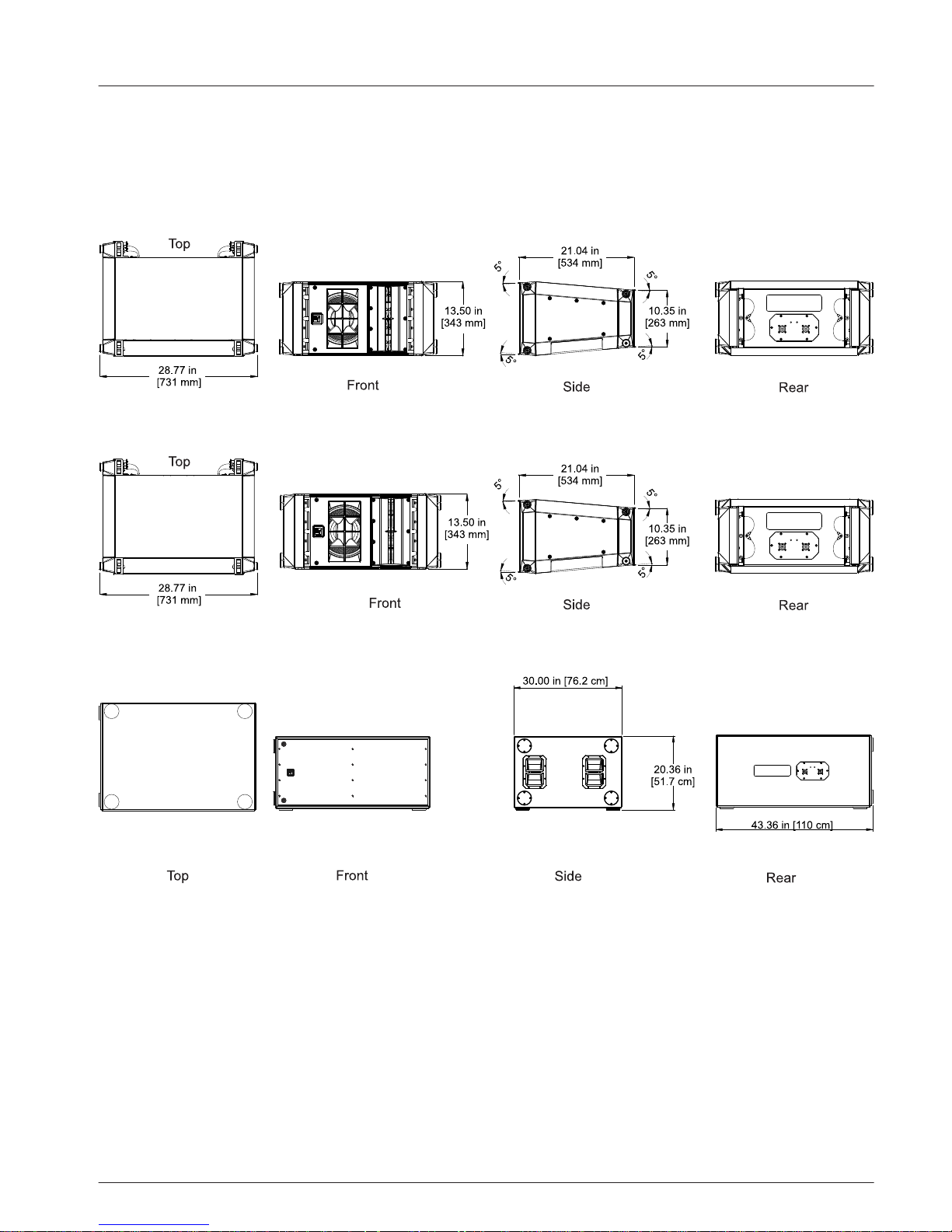
Dimensions
Figure 3.1: X1-212/90 dimensions
Figure 3.2: X2-212/90 dimensions
Figure 3.3: X12-128 dimensions
3.1
en 9
Electro-Voice Installation Manual 2015.04 | 02 | F.01U.310.953
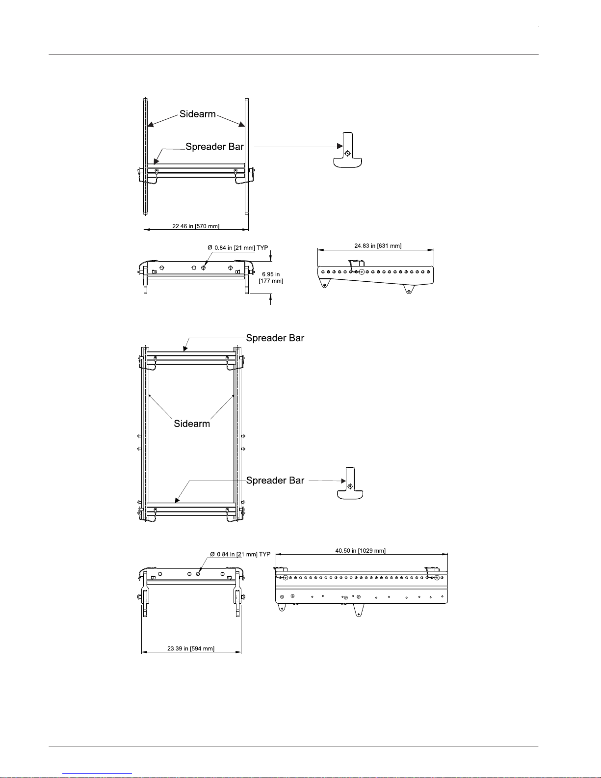
Accessories dimensions
Figure 3.4: X12TC-GRID compact grid dimensions
Figure 3.5: X12TE-GRID extended grid dimensions
3.1.1
X-LINE ADVANCE Systems
2015.04 | 02 | F.01U.310.953 Installation Manual Electro-Voice
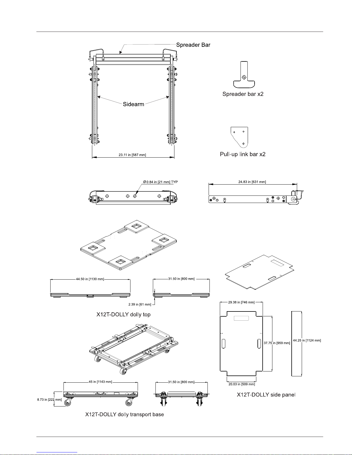
Figure 3.6: X12PU-BGK Pull-up grid dimensions
Figure 3.7: X12T-DOLLY dimensions
en 11
Electro-Voice Installation Manual 2015.04 | 02 | F.01U.310.953
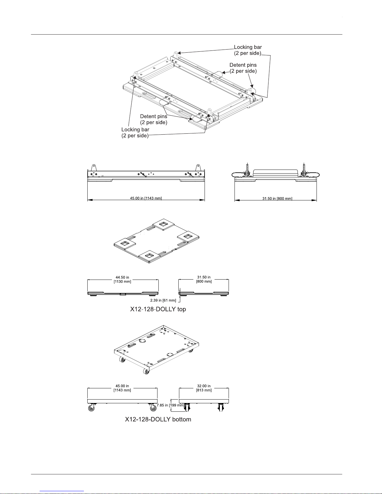
Figure 3.8: X1/X2 groundstack dimensions
Figure 3.9: X12-128-DOLLY dimensions
X-LINE ADVANCE Systems
2015.04 | 02 | F.01U.310.953 Installation Manual Electro-Voice
Designing an X1 or X2 array
Applications for which X-Line Advance arrays are most
appropriate
The X1 and X2 loudspeaker systems are specifically designed to construct acoustically
coherent line-arrays. Line-array systems typically consist of independent columns of
loudspeaker enclosures. The most common implementation is a stereo sound reinforcement
system with two (2) columns (left and right). Additional columns are sometimes added to
cover different seating sections of a venue, e.g., seating areas that wrap around the side or
back of a stage. An additional column is also used in left-center-right configurations, with the
center channel for speech. In some venues, where stereo is not required, good coverage can
often be obtained with a single array. A variation of such a monaural system is the exploded
array, where two (2) or more widely spaced arrays are used to provide the horizontal coverage
required. Also, a large number of arrays may be used in distributed systems, such as in an
arena.
Notice!
The X1 and X2 line arrays, even though mechanically are identical, they are not designed
acoustically to work in the same column.
The exact number of X1 or X2 loudspeaker systems in a column varies depending on the
vertical acoustic coverage required for the specific venue. Furthermore, the relative vertical
angles between the boxes and SPL also depend on the venue’s acoustic coverage
requirements. Acoustic design techniques are outside the scope of this document and the
reader is directed to LAPS 3 (Line Array Prediction Software) or later modeling software
available from the Electro-Voice website www.electrovoice.com for acoustic design assistance.
Although the full-range X1 and X2 loudspeaker systems shown in Dimensions, page 9 are not
horizontally symmetrical, their acoustical polar responses are substantially symmetrical. Thus,
stereo left and right arrays, or left-center-right arrays may be constructed with the
loudspeakers in their normal right-side-up orientation.
Determining X1 and X2 array configuration with LAPS 3
LAPS 3 is software written in MATLAB with Excel-spreadsheet-based frontend interface for
determining optimum array configurations for a given venue and trim heights. The current
version of LAPS 3 is downloadable from the Electro-Voice
website www.electrovoice.com.
4
4.1
4.2
en 13
Electro-Voice Installation Manual 2015.04 | 02 | F.01U.310.953

Preparing X-Line Advance elements for installation
Recommended preflight procedures
For any installed sound system, certain checks made at the installer’s place of business can
prevent expensive on-site delays. A short-list follows, and sets the stage for proper array
performance:
1. Unpack all loudspeakers in the shop.
2.
Check for proper model numbers.
3. Check the overall condition of the loudspeakers.
4. Check for continuity at the loudspeaker inputs.
It is a good idea, once on-site and the loudspeakers are connected, to check again for
continuity at the power-amplifier end.
Element configuration
After using LAPS 3 to design an appropriate array, it is recommended all necessary hardware
and accessories to suspend the array are checked and accounted for. Ensure all hardware is in
good working order, no defects, damage or imperfections are present, and all hardware is
capable of meeting or exceeding the total load requirements of the entire array.
5
5.1
5.2
X-LINE ADVANCE Systems
2015.04 | 02 | F.01U.310.953 Installation Manual Electro-Voice
Rigging system
Overview of the flying system
The IRS (Integrated Rigging System) on X1 and X2 was developed as a faster, safer way of
flying, aiming and landing a large vertical array.
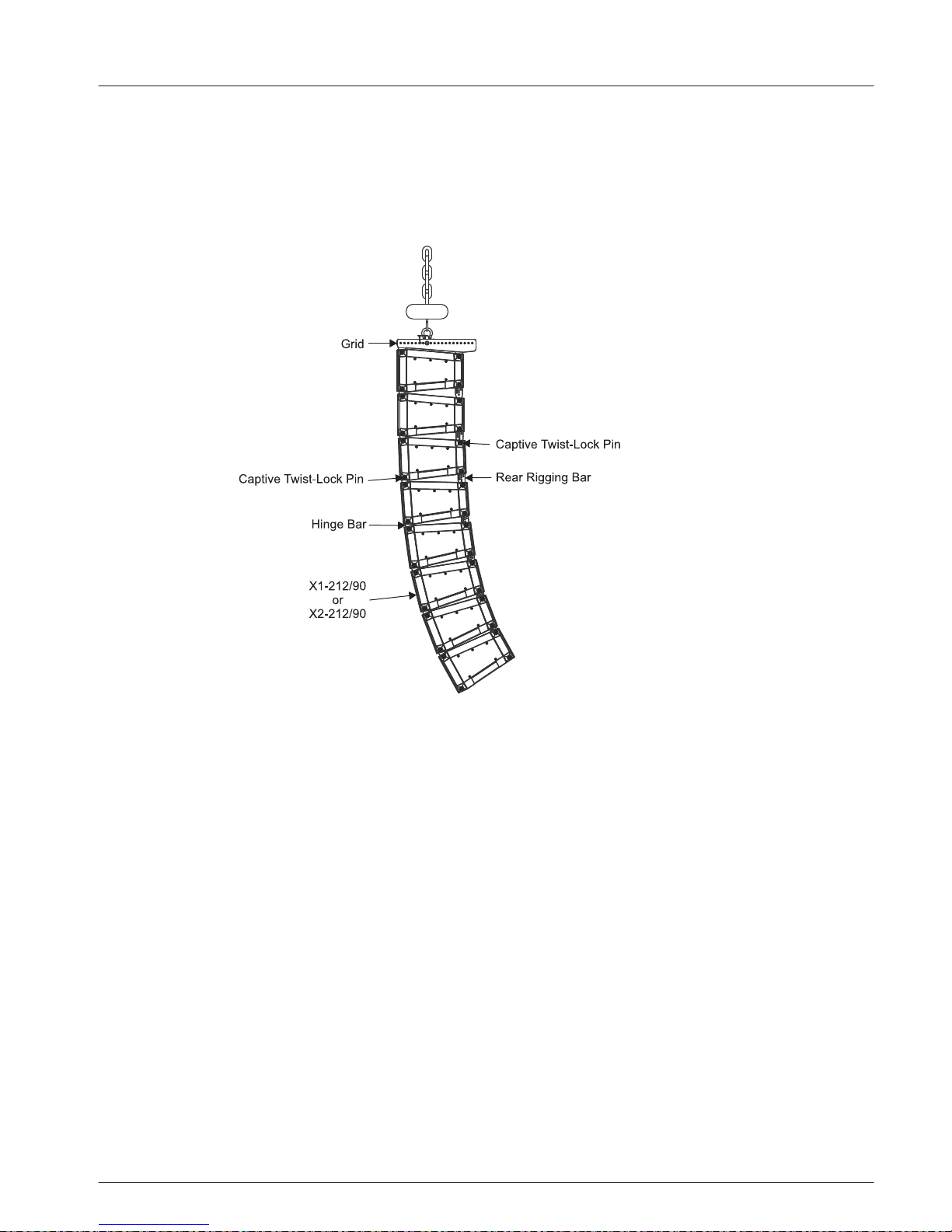
Figure 6.1: Integrated Rigging System
Rigging the boxes together
The individual elements are fastened together by spring-loaded captive twist lock pins. The
captive twist lock pins are located at each of the four (4) upper corners and two (2) lower
front corners of each box. The upper pins attach each box to the extended link bars of the box
above it or grid. The pins are locked in their retracted (Open) position by grasping each pin
knob and pulling out as far as it will go, then turning the knob left or right to lock the pin in
the retracted position. The link bars of the box or grid above can then be dropped safely into
the V-blocks located at the top corners of the aluminum rigging. There is no fumbling for pin
holes because alignment is accomplished by the V-blocks. Once seated, the pins are engaged
by simply twisting each knob to unlock, allowing the spring to fire the pin into position. Lower
front link bars are released or retracted and locked into position the same way. Rear link bars
are set to the desired splay angle position with standard quick-release pins.
6
6.1
6.2
en 15
Electro-Voice Installation Manual 2015.04 | 02 | F.01U.310.953
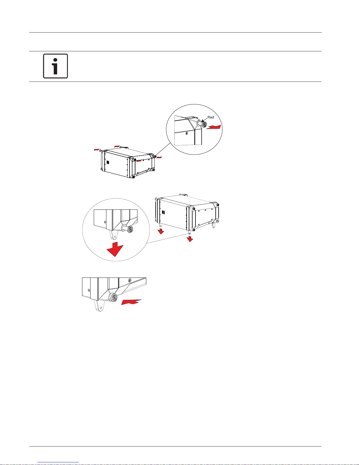
To rig the boxes together, do the following:
Notice!
Before flying the array verify the captive twist lock pins are fully engaged in the rigging (no
red showing between the pin knob and the box).
1. Pull and twist four (4) captive twist lock pins on the top of the lower enclosure.
Four (4) captive twist lock pins are locked in the retracted (open) position.
2. Extend the two (2) front link bars on the bottom of the upper enclosure.
3. Lock the two (2) captive twist lock pins for the two (2) front link bars.
4. Guide the link bars of the box or grid above into the V-blocks located at the top corners
of the aluminum rigging.
5. Twist the four (4) captive twist lock pins
top of the lower enclosure.
Four (4) captive twist lock pins are unlocked in the engaged (Closed) position.
X-LINE ADVANCE Systems
2015.04 | 02 | F.01U.310.953 Installation Manual Electro-Voice
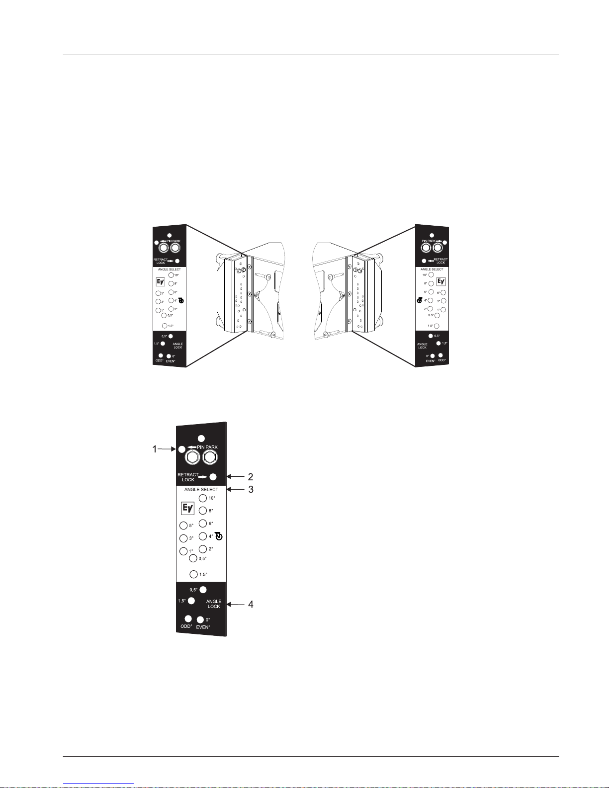
Setting rear link angles
The rear link angle is selected by choosing corresponding holes in the white ANGLE SELECT
sections of the rear rigging on each side (0°, 0.5°, 1°, 1.5°, 2°, 3°, 4°, 5°, 6°, 8°, 10°) as
determined by LAPS 3. Unless the rigging is locked into a rigid configuration by secondary pins
in the lower black ANGLE LOCK sections, the elements always default to 0° when lifted. Use
of the bottom pull-up grid accessory enables the array to be easily compressed with each
element stopping at its pre-selected splay angle. Smaller arrays may be rigidly pinned by lifting
the rear of each box until it hits the pre-selected angle stop, then inserting a second pin per
side into the appropriate hole in the ANGLE LOCK section. There is no fumbling for pin holes
because when lifted, the rigging will stop at the pre-selected position.
Figure 6.2: X1/X2 Rigging Hardware
Rear link angle selection
1. PIN PARK is used to park the unused pin.
2. RETRACT LOCK is used to lock the link bar in stored position.
3. ANGLE SELECT (in the white section) is used to set the desired splay angle from the
report from LAPS 3. This is used for both fixed-pin angles and rear-rigging compression
pull up.
▪ 0.5, 1°, 1.5, 2°, 3°, 4°, 5°, 6°, 8°, and 10° are the available angles for selection. For a 0º
angle, use the 0º angle hole in the Angle Lock section below.
6.3
en 17
Electro-Voice Installation Manual 2015.04 | 02 | F.01U.310.953
▪ DOLLY WHEEL (the 4º hole) is used to secure the bottom box of a stack to a dolly.
4. ANGLE LOCK (in the bottom black section) is used to lock the rear link bar for fixedpinned angles. Except for a 0º angle, this section is not used for rear-rigging compression
pull up.
▪ 0.5° and 1.5° are used to lock those two (2) angles.
▪ ODD° is used to lock the odd number angles.
▪ EVEN°
is used to lock the even number angles and the 0º angle.
Single pin and double pin
Single pin compression method is used when a pull-up to the grid is employed to pull the rear
rigging together into compression. Double pin is used to set the rear rigging at fixed angles.
Ensure both sides of the loudspeaker are pinned identically.
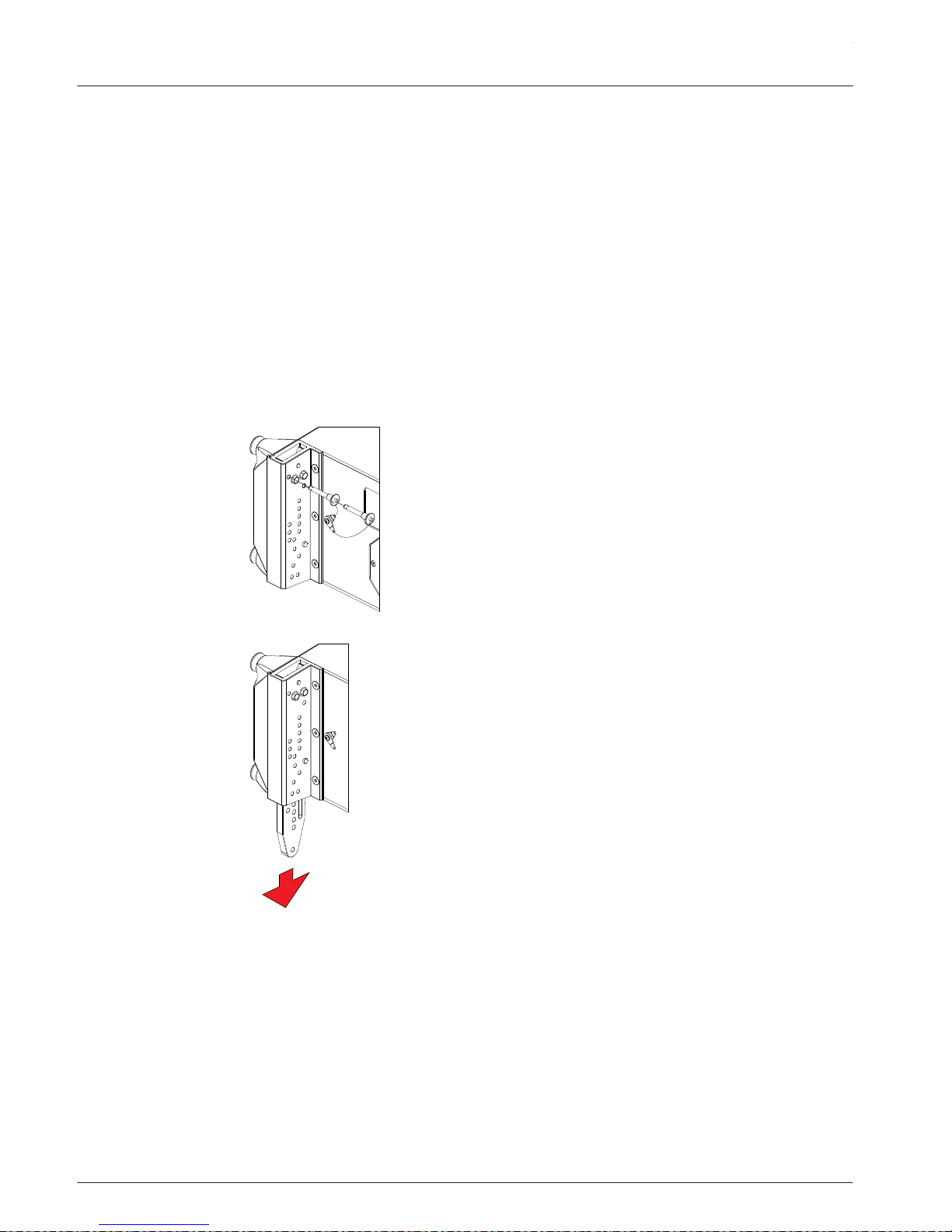
To single pin or double pin, do the following:
1. Release the quick-release pin from RETRACT LOCK hole.
2. Lower rear link bar.
X-LINE ADVANCE Systems
2015.04 | 02 | F.01U.310.953 Installation Manual Electro-Voice
3. Insert quick-release pin into desired ANGLE SELECT degree hole.
Verify pin is thoroughly pushed in and the blue button is released.
4. If using single pin repeat steps 1-4 on the other side of the loudspeaker.
Repeat this process on all elements in the array setting the angles per the report from LAPS
3.
OR
If using double pin continue to the next step.
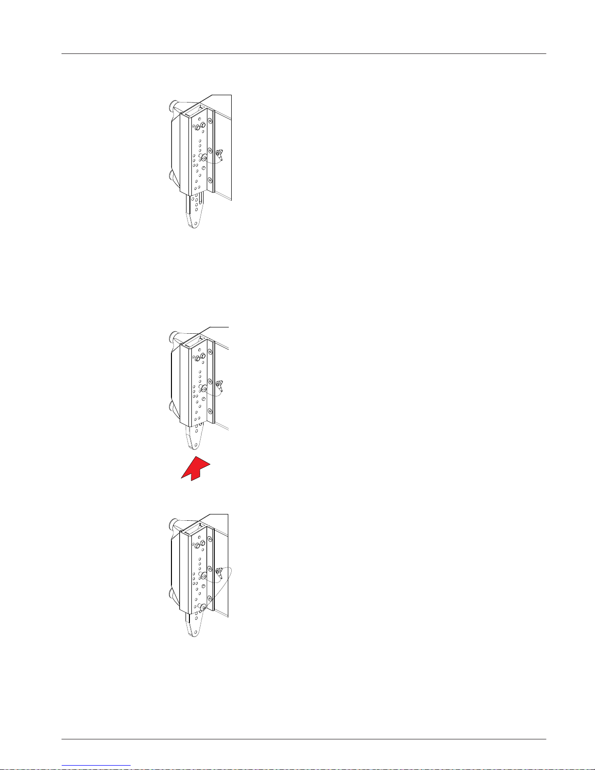
5. Double pin: Push the rear link bar up until it contacts the stop pin in the angle select
hole.
6. Insert the second quick-release pin into desired ANGLE LOCK hole.
Verify pin is thoroughly pushed in and the blue button is released.
7. Repeat steps 1-7 on the other side of the loudspeaker.
Repeat this process on all elements in the array setting the angles per the report from
LAPS 3.
en 19
Electro-Voice Installation Manual 2015.04 | 02 | F.01U.310.953

Deciding which grid configuration to use
Choosing a grid is determined by the system down or up angles in combination with the
number of elements in the array and the splay angle between them. To determine which grid
model will achieve your desired angle or where the safety limitations are for the arrays, please
use LAPS 3 to design your array, and observe all warnings and limitation messages displayed
by the software.
X12TC-GRID compact grid
The X12TC-GRID compact grids are appropriate for arrays where extreme up or down angles
are not required. It is rated for a maximum hang of up to 24 X1 or X2 elements in a single
column. Use LAPS 3 to determine if X12TC-GRID combined with the number of elements will
achieve the acoustical coverage in the venue at a safe working load. For more information, see
Rigging structural strength ratings and safety factors , page 54
Notice!
X12TC-Grid comes with one (1) spreader bar only. The use of a second spreader bar is not
recommended with this grid.
X12TC-GRID includes one (1) spreader bar and two (2) sidearms. The spreader bar has four
(4) 0.84-inch (21.4 mm) holes through it for use as attachment points. The hole near the
center of the bar labeled PICK HERE is used for lifting a single point hang. This hole is slightly
off-center to compensate for the center of gravity of the respective X1 and X2 systems.
Pay close attention to which way the spreader bar is oriented with respect to the loudspeaker
systems. Compare the wording on the left end of the spreader bar to the input panel label on
the loudspeaker. For an X1 system, the bar should read X1 THIS SIDE TO REAR and for an X2
system it should read X2 THIS SIDE TO REAR.
!
Caution!
Verify the correct spreader bar orientation before lifting the array.
Failure to comply with this instruction results in the entire array tilting to one (1) side at an
unsafe angle.
Figure 6.3: X1/X2 spreader bar
The hole labeled SAFETY HERE is for attachment of a safety line if required by local
regulations. If used, ensure there is minimal slack in the safety line but it is not so tight as to
interfere with the vertical alignment of the array hanging from the pick point. The two (2)
6.4
6.4.1
X-LINE ADVANCE Systems
2015.04 | 02 | F.01U.310.953 Installation Manual Electro-Voice

outer holes may be used for lifting as a two-point lateral hang, often useful to prevent twisting
of the array. In this situation, lifting and suspension lines must not exceed 15° from vertical
and both points must be lifted equally so the array is never more than ±5° from horizontal
during the lift.
!
Caution!
Do not lift an array by attaching directly to the sidearms.
Lift with the supplied spreader bar(s) only.
The compact grid sidearms are usually attached with the excess overhang at the rear to allow
for greater down-angle possibilities. For situations where more up-angle is possibly required,
such as covering a high balcony in a theater, the grid can be reversed with the excess grid
length overhanging the front of the array.
Installing the X12TC-GRID to an X1 or X2 loudspeaker
When the compact grid with its single spreader bar is used, the trim angle of the array is
determined by the front-to-back attachment position of the spreader bar. This information is
provided by LAPS 3, a function of the array makeup and desired vertical aiming.
!
Caution!
Verify each end of the spreader bar is pinned in the same number hole on both sidearms.
Ensure the pins attaching the grid sidearms are fully locked into the holes in the ends of the
spreader bar.
Notice!
Using the PICK HERE alone requires a tie-off to stabilize the horizontal rotation of the array.
Notice!
Before flying the array verify the captive twist lock pins are fully engaged in the rigging (no
red showing between the pin knob and the box).
To install the X12TC-GRID, do the following:
1. Pull and twist two (2) captive twist lock pins (A) on one side of the loudspeaker.
Two (2) captive twist lock pins are locked in the retracted (Open) position.
2. Guide one (1) sidearm (B) into the rigging tubes until it is fully seated in the V-blocks.
en 21
Electro-Voice Installation Manual 2015.04 | 02 | F.01U.310.953

3. Twist the two (2) captive twist lock pins.
Two (2) captive twist lock pins are unlocked in the engaged (Closed) position.
4. Repeat steps 1-3 on the opposite side of the loudspeaker.
Two (2) sidearms are attached to the loudspeaker.
5. Attach
one (1) spreader bar to the two (2) sidearms using the hole locations from LAPS
3.
6. Verify the spreader bar is correctly oriented for the model of loudspeaker (X1 or
X2)
being rigged.
7. Attach a 5/8-inch shackle to the hole labeled PICK HERE on the spreader bar.
Ensure the shackle is rated for overhead lifting.
X-LINE ADVANCE Systems
2015.04 | 02 | F.01U.310.953 Installation Manual Electro-Voice

8. Attach the lifting cable/chain to the shackle.
9. Verify all hooks, pins, shackles, and other associated rigging components are properly
positioned and secure before lifting the array.
X12TE-GRID extended grid
X12TE-GRID extended grid is available for flying arrays that require greater up or down angles
than what are possible with the X12TC-GRID compact grid. The front and rear link bars are
adjustable in three different positions to facilitate the extreme up-angles sometimes required
in venues with multiple high balconies. The additional length of the X12TE-GRID also enables
more extreme down-angles from a single point than would otherwise be possible. Note that
de-rating occurs as the angle becomes more extreme. Consult LAPS 3 for limitations in a
particular array configuration. The X12TE-GRID is also required in order to use the X12PU-BGK
pull-up grid to aim an array using the rear compression rigging method. The X12TE-GRID
comes with two spreader bars to allow the use of two motors to provide easy angle control of
large arrays, especially when compression rigging is used. The resulting fore-and-aft pick
points also provide better horizontal stability than a typical rear tie-off point.
Each spreader bar has four (4) 0.84-inch (21.4 mm) holes through it for use as attachment
points. The hole near the center of the bar labeled PICK HERE is used for lifting a single point
hang. This hole is slightly off-center to compensate for the center of gravity of the respective
X1 and X2 systems.
Pay close attention to which way the spreader bar is oriented with respect to the loudspeaker
systems. Compare the wording on the left end of the spreader bar to the input panel label on
the loudspeaker. For an X1 system, the bar should read X1 THIS SIDE TO REAR and for an X2
system it should read X2 THIS SIDE TO REAR.
!
Caution!
Verify the correct spreader bar orientation before lifting the array.
Failure to comply with this instruction results in the entire array tilting to one (1) side at an
unsafe angle.
6.4.2
en 23
Electro-Voice Installation Manual 2015.04 | 02 | F.01U.310.953
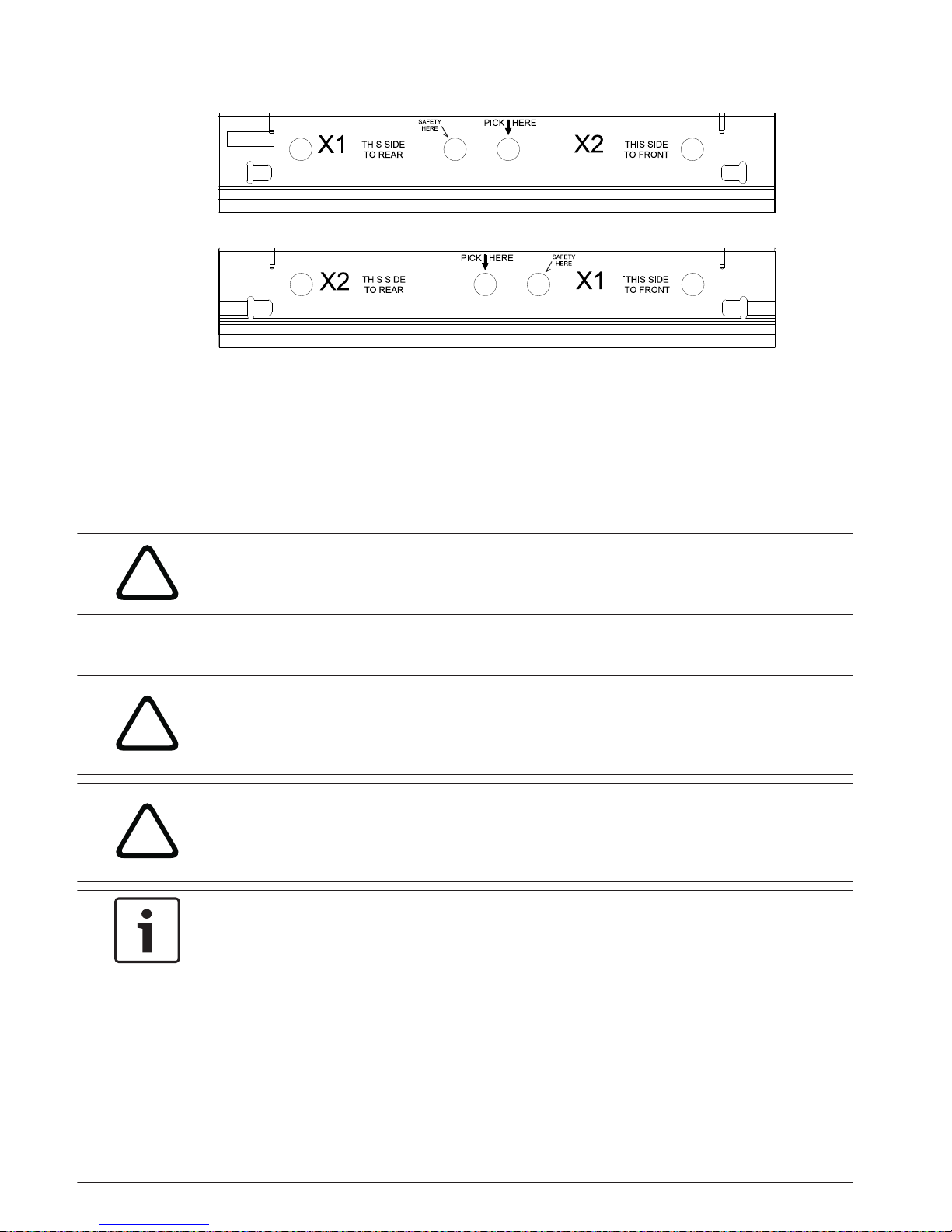
Figure 6.4: X1/X2 spreader bar
The hole labeled SAFETY HERE is for attachment of a safety line if required by local law. If
used, ensure there is minimal slack in the safety line(s) but it is not so tight as to interfere
with the vertical alignment of the array hanging from the pick point. The two (2) outer holes
may be used for lifting as a two-point lateral hang, often useful to prevent twisting of the array
or in situations where a 4-point hang is required with two (2) spreader bars. In this situation,
lifting and suspension lines must not exceed 15° from vertical and all points must be lifted
equally so the array is never more than ±5° from horizontal during the lift.
!
Caution!
Do not lift an array by attaching directly to the sidearms.
Lift with the supplied spreader bar(s) only.
Installing the X12TE-GRID to an X1 or X2 loudspeaker
!
Caution!
The extended grid sidearms are heavy and likely to tip if not secured, potentially causing
damage and/or personal injury if one (1) should fail.
Always maintain a good grip on the sidearm until both twist-lock pins are fully engaged.
!
Caution!
Verify each end of the spreader bar is pinned in the same number hole on both sidearms.
Ensure the pins attaching the grid sidearms are fully locked into the holes in the ends of the
spreader bar.
Notice!
Before flying the array verify the captive twist lock pins are fully engaged in the rigging (no
red showing between the pin knob and the box).
X-LINE ADVANCE Systems
2015.04 | 02 | F.01U.310.953 Installation Manual Electro-Voice
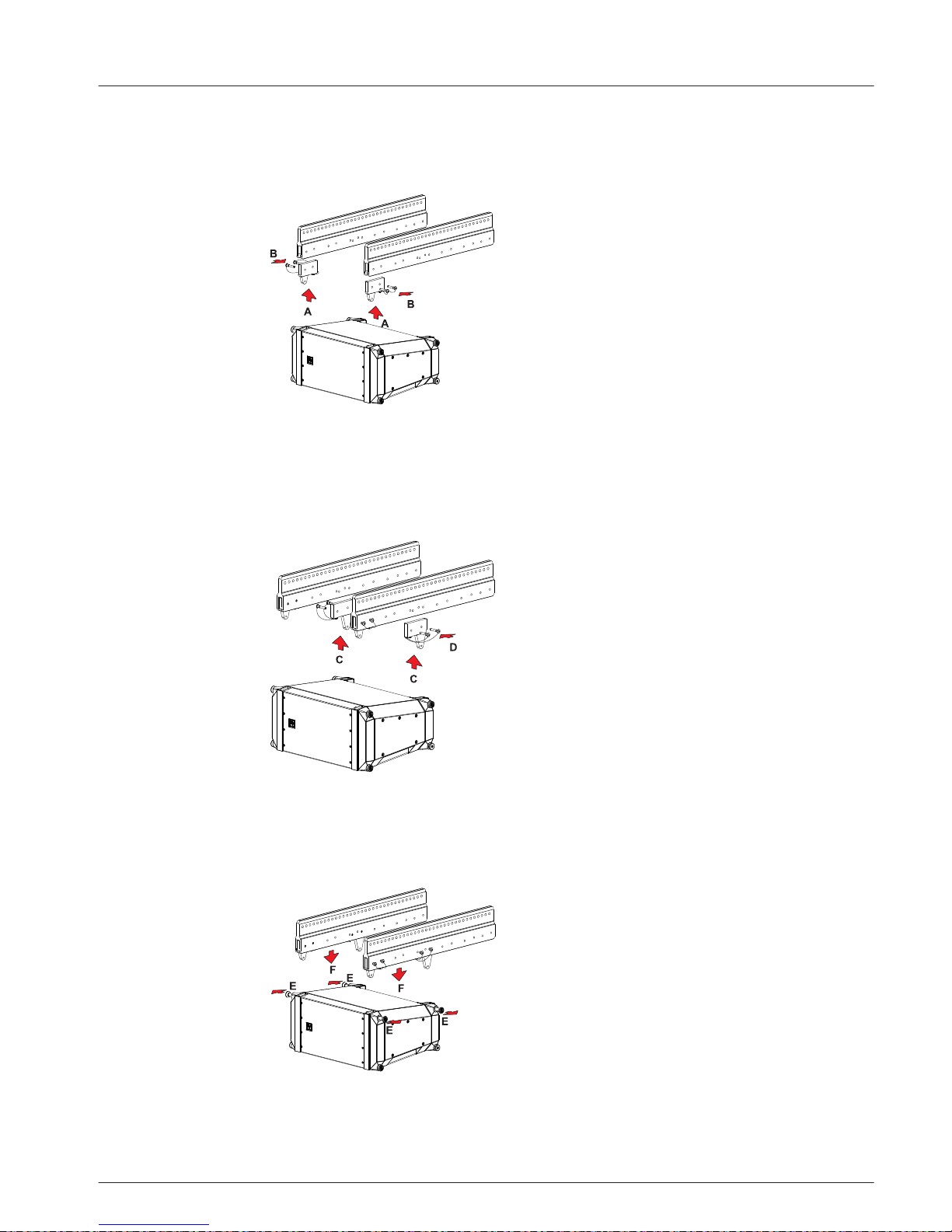
To install the X12TE-GRID, do the following:
1. Attach
front link bars (A) to the sidearms.
Consult LAPS 3 for the A, B, or C position of the front link bar for the particular array being
flown.
2. Insert the attached quick-release pins (B).
Verify all quick-release pins are inserted completely through the sidearm and securely locked
in position.
3. Attach
rear link bars (C) to the sidearms.
Consult LAPS 3 for the rear link bars position corresponding to the A, B, or C position of the
front link bar for the particular array being flown.
4. Insert the attached quick-release pins (D).
Verify all quick-release pins are inserted completely through the sidearm and securely locked
in position.
5. Pull and twist two (2) captive twist lock pins
(E).
Two (2) captive twist lock pins are locked in the retracted (open) position.
6. Guide one (1) sidearm (F) into the rigging tubes until it is fully seated in the V-blocks.
Keep a good grip on the sidearm until both pins are completely engaged through the rigging.
en 25
Electro-Voice Installation Manual 2015.04 | 02 | F.01U.310.953

7. Twist the two (2) captive twist lock pins (G).
Two (2) captive twist lock pins are unlocked in the engaged (Closed) position.
8. Repeat steps 6-8 on the opposite side of the enclosure.
The second sidearm is attached to the loudspeaker.
9. Verify the spreader bar
is correctly oriented for the model of loudspeaker (X1 or X2)
being rigged.
Both spreader bars must face the same way with their pick point holes aligned.
10. Attach a single spreader bar (H) to the two (2) sidearms at the hole position determined
by LAPS 3.
11. If using two (2) motors and two (2) spreader bars, attach one (1) spreader bar (H) at
hole #1 and one (1) spreader bar (I) at hole #33.
12. Attach a 5/8-inch shackle to the hole labeled PICK HERE on the spreader bar(s).
Ensure the shackle is rated for overhead lifting.
13. Attach the
lifting cable/chain(s) to the shackle(s).
14. Verify all hooks, pins, shackles, and other associated rigging components are properly
positioned and secure before lifting the array.
X-LINE ADVANCE Systems
2015.04 | 02 | F.01U.310.953 Installation Manual Electro-Voice

X1 or X2 Extended Grid Rigging Configurations
!
Caution!
Do not lift an array by attaching directly to the sidearms.
Lift with the supplied spreader bar(s) only.
Figure 6.5: X12TE-GRID - Single
Figure 6.6: X12TE-GRID - Dual
en 27
Electro-Voice Installation Manual 2015.04 | 02 | F.01U.310.953

X12PU-BGK pull-up kit
X12PU-BGK pull-up kit is used when the compression rigging method is being used with an
array or when extreme down angles beyond the capabilities of the extended grid are required.
This is a way to achieve extreme down angles, such as might be encountered in a distributed
arena system. When using one (1) X12TC-GRID and one (1) X12PU-BGK in this fashion, the
angle between the suspension lines must never be allowed to exceed 30°. For maximum
angles, restrictions and limitations, consult LAPS 3 and follow all warning, limitations and
restrictions recommended by the software.
Figure 6.7: Double pick point maximum angle
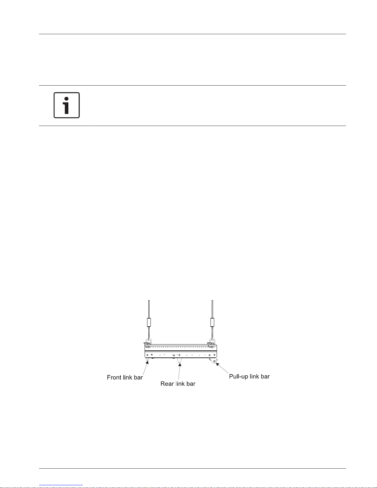
For rear-rigging compression, the user must build a pull-up assembly. The X12PU-BGK includes
two (2) spreader bars and two (2) pull-up link bars. One (1) spreader bar attaches to the
X12PU-BGK bottom. The other spreader and the two (2) pull-up link bars attach to the bottom
of the X12TE-GRID top grid at the rear-most attachment position. The pull-up assembly
attaches between the two (2) spreader bars. The remaining components of the pull-up
assembly must be provided by the user.
A lever hoist will be used for the pull-up assembly. The user extends the chain from the hoist
and attach to the pull-up spreader bar on the X12TE-GRID using a 5/8 shackle. One (1) end of
a 3-foot-long (or one-meter-long) wire rope sling attaches to the bottom hook of the hoist. The
other end of the wire rope sling attaches to the spreader bar on the X12PU-BGK using a 5/8inch shackle.
The user provides the two (2) 5/8-inch shackles, wire rope sling, and lever hoist. Electro-Voice
recommends using a wire rope sling with a load rating of at least 2400 pounds (or 1100 kg)
for vertical configuration.
Electro-Voice recommends using a Columbus-McKinnon model 653
lever hoist having a 1.5-ton rating and 20 feet of chain.
Using these components, the pull-up assembly accommodates a quantity of 8 to 20 X1 or X2
loudspeaker systems. This pull-up assembly has been modeled in LAPS 3. If a different pull-up
assembly is used, the angle at which an array hangs may different from what LAPS 3 predicts.
Proper spreader bar orientation must be maintained when used in conjunction with the
pull-up grid. Always orient bars to the system model when viewed right-side-up, and then
simply rotate the top pull-up spreader bar upside-down before attaching to the pull-up bars at
the rear of a X12TE-GRID. Do not swap ends! Correct orientation puts the pick holes of all
spreader bars in alignment in the same vertical plane. The spreader bar at the bottom of an
array will always be oriented right-side-up.
6.4.3
X-LINE ADVANCE Systems
2015.04 | 02 | F.01U.310.953 Installation Manual Electro-Voice

Figure 6.8: X1/X2 spreader bars properly orientated for use with pull-up grid for X2 array.
Figure 6.9: X12PU-BGK installed
Using the X12PU-BGK with an X12TE-GRID for compressing an X1 or X2 array
The X12PU-BGK pull-up bar is installed on the bottom-most element in the array.
!
Caution!
Verify each end of the spreader bar is pinned in the same number hole on both sidearms.
Ensure the pins attaching the grid sidearms are fully locked into the holes in the ends of the
spreader bar.
To install the X12PU-BGK, do the following:
1. Extend and lock the front
link bars.
2. Extend and lock the rear link bars.
3. With the sidearm V-blocks facing up and the solid bar facing the rear, guide the V-blocks
on the extended link bars (A).
Do not release the sidearm until it is securely attached to the loudspeaker.
4. Insert the attached quick-release pins (B) through each sidearm and link bars, front and
rear.
Ensure all quick-release pins are completely through the sidearms and securely locked.
en 29
Electro-Voice Installation Manual 2015.04 | 02 | F.01U.310.953

5. Attach a spreader bar to the two (2) side arms in the rear.
6. X12PU-BGK is assembled.
Using the X12PU-BGK with the X12TE-GRID
To use the X12PU-BGK with theX12TE-GRID, do the following:
1. Attach the
two (2) pull-up link bars to the sidearms.
2. Insert the attached quick-release pins.
Verify all quick-release pins are inserted completely through the sidearm and securely locked
in position.
For more information, see X12TE-GRID using X12PU-BGK to pull-up to grid, page 43.
X-LINE ADVANCE Systems
2015.04 | 02 | F.01U.310.953 Installation Manual Electro-Voice

X12T-DOLLY and X12-128-DOLLY
X12T-Dolly: Dolly is used for transporting X1
or X2 loudspeaker systems. The dolly
accommodates two (2) columns of X1 or X2 loudspeaker systems stacked three (3) high for
transportation (Total of six (6) systems per dolly). Systems are secured to the dolly via their
rigging pins. A rigid top cover provides a solid surface for stacking and two (2) dolly side
panels provide protection for speaker grilles. The dolly may also be used as a ground stack
platform, either wheeled or stationary by using the dolly top cover.
X12-128-Dolly: Dolly is used for transporting X12-128 subwoofers. The dolly will accommodate
one (1) column of X12-128 subwoofers stacked two (2) high for transportation. The systems
are strapped down with ratchet straps for additional protection during transport.
Notice!
Dolly stacking limits
X12T-DOLLY accommodates two (2) columns of
X1 or X2 loudspeaker systems stacked three
(3) high for transportation. The dolly is designed for a total of six (6) loudspeakers per dolly.
X12-128-DOLLY accommodates one (2) column of
X12-128 subwoofers stacked two (2) high
for transportation. The dolly is designed for a total of two (2) subwoofers per dolly.
6.5
en 31
Electro-Voice Installation Manual 2015.04 | 02 | F.01U.310.953

Stacking X1 & X2 loudspeakers onto a X12T-DOLLY
!
Caution!
Two (2) person lift and placement is recommended for the heavier loudspeakers. Single
person lift and placement of heavier loudspeakers could cause injury.
!
Caution!
Ensure the correct dolly pins are released from the dolly base. There are four (4) dolly pins
for each stack on the dolly base. There is a total of eight (8) pins on the dolly base.
If the column of enclosures is lifted with the dolly pins still locking to the speakers to the
base, the dolly base will lift and tip. Property damage and personal injuries may occur.
Notice!
Dolly Wheel (the 4º hole):
The bottom element to be landed on the dolly base must be pinned in 4° hole ( ) in the
ANGLE SELECT section. Compress the rear link bars until they contact the angle select pin
and lock by adding a second pin in the EVEN holes of the ANGLE LOCK section.
Ensure the two (2) front link bars are lowered and locked.
To stack X1 or X2 loudspeakers onto a dolly, do the following:
1. Release the four (4) dolly pins (A)
on the dolly.
All four (4) dolly lock pins are released and hanging from the dolly.
2. Guide the loudspeaker (B) onto the dolly with the grille facing out.
3. Insert the
four (4) dolly pins (C) to lock the loudspeaker onto the dolly.
Ensure the dolly pins are secure.
4. Pull and twist the four (4) captive twist lock pins (D).
All four (4) captive twist lock pins are in the unlock position.
6.5.1
X-LINE ADVANCE Systems
2015.04 | 02 | F.01U.310.953 Installation Manual Electro-Voice

5. Guide the next loudspeaker (E) onto the stack.
Ensure the loudspeaker rear link bars angles are set to 0° EVEN.
6. Twist the four (4) captive twist lock pins (F).
All four (4) captive twist lock pins are in the lock position. Ensure the loudspeaker is secure.
7. Repeat steps 4-6
to add up to three (3) X1 or X2’s in a single column.
8. Rotate the dolly.
9. Repeat steps 1-6 to stack the second column.
The loudspeakers can be transported on the dolly. For more information, see Transporting X1
or X2 loudspeakers, page 47.
en 33
Electro-Voice Installation Manual 2015.04 | 02 | F.01U.310.953

Groundstacking X1 or X2 loudspeakers
The dolly top is designed to be used as a groundstacking kit. Maximum recommended
groundstack height is six (6) elements.
Figure 6.10: X1 or X2 groundstacking
X-LINE ADVANCE Systems
2015.04 | 02 | F.01U.310.953 Installation Manual Electro-Voice

Stacking X12-128 subwoofer(s) onto a X12-128-DOLLY
!
Caution!
Two (2) person lift and placement is recommended for the heavier loudspeakers. Single
person lift and placement of heavier loudspeakers could cause injury.
To stack X12-128 subwoofers onto a dolly, do the following:
1. Guide one (1)
subwoofer onto the dolly.
2. Guide a second subwoofer onto the stack.
6.5.2
en 35
Electro-Voice Installation Manual 2015.04 | 02 | F.01U.310.953

Transporting subwoofers
The subwoofer dolly can be used for long-range transport.
To prepare subwoofers for transport, do the following:
1. Place the dolly top
onto the stack.
2. Run the ratchet strap under the dolly.
The ratchet strap is flat against the subwoofers and it is not twisted.
3. Align the ratchet strap
on the strap cutout on the dolly top.
4. Tighten the ratchet strap.
Dolly contents secured for transport.
X-LINE ADVANCE Systems
2015.04 | 02 | F.01U.310.953 Installation Manual Electro-Voice

Assembling and flying an array
Use LAPS 3 to design the array.
Flying arrays from the dolly
Arrays can be flown from the dolly and angles set before the array is lifted.
!
Caution!
When suspending any Electro-Voice
loudspeaker array overhead, the working-load limit must
never be exceeded for the individual enclosure rigging point, for the overall enclosure, or for
any of the rigging accessories.
!
Caution!
Do not lift an array by attaching directly to the sidearms.
Lift with the supplied spreader bar(s) only.
!
Caution!
Ensure the correct dolly pins are released from the dolly base. There are four (4) dolly pins
for each stack on the dolly base. There is a total of eight (8) pins on the dolly base.
If the column of enclosures is lifted with the dolly pins still locking to the speakers to the
base, the dolly base will lift and tip. Property damage and personal injuries may occur.
To fly an array from a dolly, do the following:
1.
If using the X12TC-GRID
, choose the forward or reversed orientation.
OR
If using the X12TE-GRID, preassemble each sidearm with front and rear link bars in the
appropriate A, B or C position.
2. Pull and twist four (4) captive twist lock pins.
Four (4) captive twist lock pins are locked in the retracted (Open) position.
3. Place one (1) grid sidearm into the rigging tubes of the first stack to be lifted and engage
both V-blocks on that side.
Ensure the sidearm is secure before releasing it.
6.6
6.6.1
en 37
Electro-Voice Installation Manual 2015.04 | 02 | F.01U.310.953

4. Twist the two (2) captive twist lock pins (A) to the unlock position.
Ensure the pins are engaged in the closed position.
5. Repeat steps 3-4 on the opposite side.
The grid is attached to the column of enclosures.
6. Using a single spreader bar with X12TC-GRID, install one (1) spreader bar between the
sidearm’s in the appropriate hole as determined by LAPS 3.
OR
If using two (2) spreader bars with X12TE-GRID, install one (1) spreader bar at hole #1
and install one (1) spreader bar at hole #33.
7.
Attach a 5/8-inch shackle(s) to the pick point on the spreader bar(s).
Ensure the shackle is rated for overhead lifting.
8. Attach the hoist chain hook to the shackle.
9. Disengage all four (4) dolly pins (B) from the bottom rigging on the column to be lifted.
10. Verify all hooks, pins, shackles, and other associated rigging components are properly
positioned and secure before lifting the array.
11. Lift column of enclosures (C).
A single column of three (3) loudspeakers is on the dolly.
12. Roll the dolly out from under the lifted column.
13. Turn the dolly around.
For more information, see X12TC-GRID compact grid, page 20 or X12TE-GRID extended grid,
page 23.
X-LINE ADVANCE Systems
2015.04 | 02 | F.01U.310.953 Installation Manual Electro-Voice
Adjusting the splay angles
Use the report from LAPS 3 to set the angles to build the array. The angle between boxes is
set on the box above. If using compression, the unused quick-release pins should be placed in
the PIN PARK holes. If using a fixed hang, lift the bottom rear of each successive box starting
from the bottom until it hits the stop at the selected angle.
Notice!
Use of a separate cable pick to support the weight of cabling is recommended, especially on
very tall arrays.
Cable weight can change the aiming angle of an array.
To set the splay angle, do the following:
1. Insert an attached quick-release pin in the correct ANGLE SELECT hole.
2. Repeat step 1 on the opposite side.
Verify both sides are identical.
3.
Single pin compression method place the second pin in PIN PARK.
OR
Double pin compress the boxes until the rear link bars contact the angle select pin.
Insert the other attached quick-release pins into the corresponding holes in the lower
black ANGLE LOCK section.
For example: 0.5°, 1.5°, EVEN numbered or ODD numbered degrees.
4. Connect the speaker cables to the input panels.
For more information, see Setting rear link angles, page 17.
For single pin compression method add a pull up assembly to X12TE-GRID only
These instructions apply only to the X12TE-GRID and using the second spreader bar with the
X12PU-BGK to pull-up to the grid. If you are using the X12TC-GRID, skip this section and
continue to the next section.
To add the pull-up assembly to the X12TE-GRID, do the following:
1. Attach the pull-up link bars to the rear of the X12TE-GRID.
2. Attach the spreader bar to the pull-up link bars on the top grid.
3. Attach a 5/8-inch shackle(s)
to the pick point on the spreader bar(s).
Ensure the shackle is rated for overhead lifting.
4. Attach the chain hook from the pull-up hoist to the shackle.
For more information, see X12PU-BGK pull-up kit, page 28.
en 39
Electro-Voice Installation Manual 2015.04 | 02 | F.01U.310.953

Adding additional elements to the array
1. Verify all hooks, pins, shackles, and other associated rigging components
are properly
positioned and secure before lifting the array.
2. Lift the first column high enough to allow the next column on the dolly to be positioned
below it.
3. Pull the four (4) captive twist lock pins (A) on the top enclosure of the next column.
All four (4) captive twist lock pins are in the unlock (Open) position.
4. Lower the suspended column (B) guiding the front link bars into the front V-blocks of the
waiting column.
Continue lowering until the rear link bars have also seated into the rear V-blocks.
5. Twist the four (4) captive twist lock pins.
Four (4) captive twist lock pins are unlocked in the engaged (Closed) position.
6.
Release the four (4) dolly pins (C) on the dolly.
All four (4) dolly lock pins are released and hanging from the dolly.
7. Repeat steps 1-6 to add additional columns to the array.
For more information, see Setting rear link angles, page 17.
If you are using the X12TE-GRID to pull-up to the grid, continue to X12TE-GRID using X12PU-
BGK to pull-up to grid, page 43.
X-LINE ADVANCE Systems
2015.04 | 02 | F.01U.310.953 Installation Manual Electro-Voice

X12TC-GRID with pull-back to venue
Using a X12TC-GRID combined with the X12PU-BGK an array can be pulled up to the venue.
Notice!
Only the double pin method is allowed when pull back to the venue is planned. Do not use
single pin compression method in this instance.
To pull-back to the venue, do the following:
1. Attach the
X12PU-BGK bottom section with spreader bar to the bottom element.
2. Attach a 5/8-inch shackle (A) to the pick point on the spreader bar.
Ensure the shackle is rated for overhead lifting.
3. Attach the pull-back hoist chain hook (B) to the shackle.
4. Verify all hooks, pins, shackles, and other associated rigging components are properly
positioned and secure before lifting the array.
6.6.2
en 41
Electro-Voice Installation Manual 2015.04 | 02 | F.01U.310.953

5. Lift the array to the desired height.
6. Adjust the top grid hoist and
bottom pull-back hoist to tilt the array to the angle
recommended by LAPS 3.
For more information, see X12TC-GRID compact grid, page 20 and Flying arrays from the dolly,
page 37.
X-LINE ADVANCE Systems
2015.04 | 02 | F.01U.310.953 Installation Manual Electro-Voice

X12TE-GRID using X12PU-BGK to pull-up to grid
Using a X12TE-GRID combined with the X12PU-BGK can be pulled up to the grid.
To pull-up to the X12TE-GRID, do the following:
1. Attach the
two (2) pull-up link bars to the sidearms.
2. Insert the attached quick-release pins.
Verify all quick-release pins are inserted completely through the sidearm and securely locked
in position.
3. Attach the
X12PU-BGK bottom section to the bottom element.
4. Attach a 5/8-inch shackle (A) to the pick point on the spreader bar.
Ensure the shackle is rated for overhead lifting.
5. Attach one (1) end (B) of the 3-foot wire rope sling to the shackle.
6. Attach the opposite end (C) of the 3-foot wire rope to the pull-up hoist.
7. Attach a chain bag to the pull-up hoist and insert the unextended chain into the chain
bag.
8. Verify all hooks, pins, shackles, and other associated rigging components are properly
positioned and secure before lifting the array.
6.6.3
en 43
Electro-Voice Installation Manual 2015.04 | 02 | F.01U.310.953

9. Lift with the pull-up host to raise the bottom element to compress the rear rigging of all
the elements in the array.
10. Lift the array to the desired height.
11. Adjust the front
and rear grid hoists to tilt the angle recommended by LAPS 3.
!
Caution!
LAPS 3 will report the force required to compress the rear rigging of all the elements.
Applying excess force can cause damage to the rigging. The use of a load cell is
recommended.
For more information, see X12TE-GRID extended grid, page 23, X12PU-BGK pull-up kit, page 28
and Flying arrays from the dolly, page 37.
Storing empty dollies
Six (6) or more dollies can easily be stored in the floor space of one (1).
X12T-DOLLY: Place the two (2) dolly side panels on top of each other with their carpeted
sides together on the dolly base between the transport rails. Pick up the top cover with link
bars pointing down and set it squarely onto the dolly base so as to nest the four (4) link bars
into the V-blocks on each corner. Insert an attached dolly pin into each corner V-block to lock
the two parts together.
X12-128-DOLLY: Nest the top cover into the dolly base and secure with ratchet strap. There is
enough clearance between the wheels that the ratchet mechanism does not interfere with
stacking. Once secured in this manner, dollies may be stacked on top of one another. Wheel
locations are the same for both dollies, as are the corresponding wheel pockets on their top
covers. Use caution when moving a tall stack of dollies. While the wheel pockets prevent the
dollies from rolling off of each other they are not enough to keep the stack together if the
bottom one (1) stops abruptly on an obstruction like the bottom of a ramp. If this is likely to
be encountered, use ratchet straps to tie the entire stack together.
6.6.4
X-LINE ADVANCE Systems
2015.04 | 02 | F.01U.310.953 Installation Manual Electro-Voice

Landing arrays onto a dolly
Landing the array elements directly onto a dolly makes transportation easier.
Notice!
Dolly stacking limits
X12T-DOLLY accommodates two (2) columns of
X1 or X2 loudspeaker systems stacked three
(3) high for transportation. The dolly is designed for a total of six (6) loudspeakers per dolly.
X12-128-DOLLY accommodates one (2) column of
X12-128 subwoofers stacked two (2) high
for transportation. The dolly is designed for a total of two (2) subwoofers per dolly.
Notice!
Dolly Wheel (the 4º hole):
The bottom element to be landed on the dolly base must be pinned in 4° hole ( ) in the
ANGLE SELECT section. Compress the rear link bars until they contact the angle select pin
and lock by adding a second pin in the EVEN holes of the ANGLE LOCK section.
Ensure the two (2) front link bars are lowered and locked.
To land an array onto a dolly, do the following:
1. Lower the array
(A) to a convenient working height above the floor.
2. If single pin compression method was used, carefully reverse the hoist and uncompress
the back of the array so the hoist has not tension and all of the elements in the array have
returned to the 0° position.
OR
If double pin method was used, lift up slightly on the rear of each of the bottom three (3)
elements and remove the quick-release pins from the lock holes. Gravity will cause the
unlocked rigging splay to revert to 0° position.
3. Disengage the eight (8) dolly pins (B) on the dolly base.
All eight (8) dolly pins are disengaged and hanging from the dolly.
6.6.5
en 45
Electro-Voice Installation Manual 2015.04 | 02 | F.01U.310.953

4. Verify the V-blocks are unobstructed and clear.
5.
Position the empty dolly under the array.
6. Ensure grilles are facing out.
7. Lower the array until the link bars engage the V-blocks on the dolly.
Guide the array to land the link bars onto the dolly rails.
8. Insert the four (4) dolly pins (C) to lock the enclosures onto the dolly.
Verify pin is thoroughly pushed in and thorough both sides of the rail.
9. Pull and twist the four (4) captive twist lock pins (D).
All four (4) captive twist lock pins are in the unlock position.
10. Lift the
column of enclosures (E).
A single column of three (3) elements is on the dolly.
11. Rotate the dolly.
12. Repeat step 2 ensuring the elements are set to 0° position.
Verify the front link bars are extended and locked and rear link bars of the bottom element
are set and locked at 4° (see Notice regarding the Dolly Wheel).
X-LINE ADVANCE Systems
2015.04 | 02 | F.01U.310.953 Installation Manual Electro-Voice

13. Repeat steps 6-8 on this column (G).
14. Insert the four (4) dolly pins to lock the enclosures onto the dolly.
Verify pin is thoroughly pushed in and thorough both sides of the rail.
Removing the grid
!
Caution!
The extended grid sidearms are heavy and likely to tip if not secured, potentially causing
damage and/or personal injury if one (1) should fail.
Always maintain a good grip on the sidearm until both twist-lock pins are fully engaged.
1. Remove the 5/8-inch shackle from the spreader bar(s).
2. Lift hoist motor to a safe height.
3.
Remove spreader bar.
4. Pull and twist the four (4) captive twist lock pins.
All four (4) captive twist lock pins are in the unlock position.
5. Remove the grid sidearms.
Transporting X1 or X2 loudspeakers
The loudspeaker dolly can be used for long-range transport.
To prepare loudspeakers for transport, do the following:
1. Ensure the scribble strip is facing out and the carpet is towards the grilles.
2. Insert a dolly side panel into the dolly base (A) to cover the grilles.
en 47
Electro-Voice Installation Manual 2015.04 | 02 | F.01U.310.953

3. Secure the locking straps to the top and bottom captive twist lock pin knobs to secure
side panels.
4. Repeat steps 1-3 on the opposite side.
5. Guide and land the dolly top link bars to align with the front V-blocks of the top
elements.
6.
Ensure the dolly top has captured the dolly side panels.
7. Push and twist the eight (8) captive twist lock pins.
All eight (8) captive twist lock pins are in the lock position. Ensure the loudspeakers are
secure.
Array building techniques
Multiple ways to fly the X12TC-GRID
X12TC-GRID can be flown in two (2) different ways—with a single grid pick point and with a
single grid pick point plus a pullback to the venue. Additionally, the grid has two (2)
orientations forward and reversed. In LAPS 3, the user must choose which way the grid will be
flown, plus the orientation of the grid.
Figure 6.11: Flying the X12TC-GRID
Single grid pick point:
In the forward orientation (1a), a small section of the grid extends behind the rear of the
loudspeaker, enabling more down tilt.
In the reversed orientation (1b), a small section of the grid extends in front of the
loudspeaker, enabling more up tilt.
Choose the pick point on the grid to achieve the desired angle as reported by LAPS 3.
Single grid pick point with a pullback to the venue:
A pullback to the venue is used when more down tilt is required than can be achieved by a
single grid pick alone. The X12PU-BGK is used at the bottom of the array.
The most common orientation would be to use the grid in the forward position (1c).
The grid can also be used in the reversed orientation with a pullback to the venue (1d). The
purpose of the pullback is to enable greater down tilt.
Choose a grid pick point near the front of the grid. This tilts the array up slightly, which makes
it easier to build because the bottom of a flown box will be a closer match to the top box on a
dolly stack.
For more information, see
6.7
6.7.1
X-LINE ADVANCE Systems
2015.04 | 02 | F.01U.310.953 Installation Manual Electro-Voice

Multiple ways to fly the X12TE-GRID
X12TE-GRID can be flown in four (4) different ways—with a single grid pick point, with a single
grid pick point plus a pullback to the venue, with two (2) grid pick points, and with two grid
picks points plus a pull-up to the grid. Additionally, the loudspeakers may be attached to the
grid in three different positions. In LAPS 3, the user must choose which way the grid will be
flown, plus the attachment position of the loudspeakers.
Figure 6.12: Flying the X12TE-GRID
Single grid pick point:
With the loudspeakers attached in the A position (2a), a large section of the grid extends
behind the rear of the loudspeaker, enabling the maximum amount of down tilt.
With the loudspeakers attached in the B position (2b), a portion of the grid extends both
behind and in front of the loudspeaker, enabling moderate tilt both up and down.
With the loudspeakers attached in the C position (2c), a large section of the grid extends in
front of the loudspeaker, enabling the maximum amount of up tilt.
Choose the pick point on the grid to achieve the desired angle as reported by LAPS 3.
Single grid pick point with a pullback to the venue:
A pullback to the venue should be used when more down tilt is required than can be achieved
by a single grid pick alone. The X12PU-BGK is used at the bottom of the array.
The most common orientation would be to use the grid with the loudspeakers attached in the
A position (2d).
A pullback to the venue can also be used with the loudspeakers attached in the B position
(2e) or in the C position (2f). Choose a grid pick point near the front of the grid. This will tilt
the array up slightly, which will make it easier to build because the bottom of a flown box will
be a closer match to the top box on a dolly stack.
6.7.2
en 49
Electro-Voice Installation Manual 2015.04 | 02 | F.01U.310.953

Double grid pick points:
Always attach the two grid pick points at the front-most and rear most attachment points on
the grid.
With the loudspeakers attached in the A position (2g), the maximum down tilt can be
obtained.
With the loudspeakers attached in the B position (2h), moderate down-tilt and up tilt can be
obtained.
With the loudspeakers attached in the C position (2i), the maximum up tit can be obtained.
The user must adjust the front and back hoist motors to achieve the angle reported by LAPS 3.
Double grid pick points plus a pull-up to the grid:
Using a pull-up to the grid enables the loudspeaker to be lifted off the dollies with the boxes
hanging straight at 0º, then pull the boxes their correct angle using a hoist in the pull-up
assembly.
The X12PU-BGK is used at the bottom of the array.
Always attach the two grid pick points at the front-most and rear most attachment points on
the grid.
Always attach the loudspeakers in the A position, furthest away from the pick point (2j).
It is not recommended to use a pull-up to the grid with the loudspeakers in the B position (2k)
or the C position (2l). Because the B and C positions are so close to the pull-up attachment
point on the grid, excessive forces result in the pull-up assembly.
With large arrays, it is possible for a single grid pick point to be in a safe condition once the
pull-up is pulled into compression, but the user would pass through an unsafe condition while
building an array. Therefore we recommend using two grid pick points to avoid the possibility
of an unsafe condition.
For large arrays, the force required to pull the rear rigging of all boxes into compression may
exceed the pull-up assembly maximum rating. If this occurs, it may be necessary to pin several
boxes at the top of the array at fixed angles. If so, LAPS 3 will return a message telling the
user how many boxes to fix pin.
For more information, see .
Array build strength considerations
LAPS 3 reports when the working-load limits for any of the elements in the array are
exceeded. Having an understanding of the structural advantages and disadvantages of
different array build configurations allows the user to select the best option to meet their
needs.
Comparing array structure strengths shows the same array constructed in four (4) different
ways: single grid pick point, single double grid pick points, double grid pick points with a pullup to the grid, and single pick point with a pullback to venue. Because the array construction
is different, the forces throughout the array are different. This results in different structural
ratings.
6.7.3
X-LINE ADVANCE Systems
2015.04 | 02 | F.01U.310.953 Installation Manual Electro-Voice

Figure 6.13: Comparing Array Structural Strengths
The arrays in Figures 3a and 3b are the weakest. The highest force in both of these arrays will
be on the rear rigging points of the top box. The long length of the X12TE-GRID extended
behind the loudspeaker acts as a large lever arm (like a wrench) that significantly increases
the force on the top enclosure rear rigging. Another way to visualize this is to think of the grid
being held in a fixed position. Because the center of gravity of the entire loudspeaker column
is so far towards the back, the column will tend to rotate counterclockwise to tilt up. The rear
rigging of the top enclosure will be in tension resisting the rotation.
Whenever a large portion of grid is extended behind the top loudspeaker as shown in Figures
3a and 3b, fewer boxes will be allowed to be suspended before the working-load limit of the
top box rear rigging is exceeded. This condition most commonly occurs with the X12TE-GRID
with the loudspeakers are in the A position. The same condition can occur when a large
portion of grid is extended in front of the top loudspeaker. This could occur with a steep uptilt angle with the X12TE-GRID with the loudspeakers in the C position on the grid. The X12TCGRID is not subject to this condition, because the grid is just slightly longer than the
loudspeaker enclosures.
The array in Figure 3d is the strongest because the load is shared between the top and bottom
of the array. This configuration will allow the highest number of boxes to be suspended and is
most commonly employed when a greater down-tilt angle is required.
Unless extreme down-tilt angles are employed, the highest forces in the array in Figure 3d will
be on the rigging of the top box. The X12PU-BGK bottom grid does not have as high of
strength rating as the top grids X12TC-GRID or X12TE-GRID. In the unlikely event that the
working-load limits of the X12PU-BGK are exceeded, one of the top grids may be substituted.
The array configuration shown in Figure 3c has greater capability than those shown in Figure
3a and 3b, but less capability than the array shown in Figure 3d. In this case, the load of the
loudspeaker column is shared between the rigging attachment points of the top box and the
pull-up assembly. However, the pull-up to the grid introduces forces that otherwise would not
exist due to gravity alone. For the array configuration in Figure 3c, the highest forces typically
occur at either the top box or at one of the boxes near the bottom of the array.
en 51
Electro-Voice Installation Manual 2015.04 | 02 | F.01U.310.953

Subwoofer arrays
The X12-128
is designed for multiple applications. It may be used as a forward standard array
or as a cardioid array. It has rubber feet on the bottom for horizontal orientation or on one (1)
side panel for vertical orientation.
In the input panel you have a choice to connect the subwoofer in either parallel (4 ohm) or
dual (8 ohm) modes for optimum subwoofer array control.
Subwoofer array configuration
Notice!
For cardioid arrays you must use the correct system setting processing and amplifying
forward firing and rear firing subwoofers separately.
7
7.1
X-LINE ADVANCE Systems
2015.04 | 02 | F.01U.310.953 Installation Manual Electro-Voice

Subwoofer cardioid options
The X12-128
cardioid subwoofer arrays can be used to direct the output of an array of
subwoofers in order to limit excessive amounts of bass in undesired areas. These arrays can
be used to keep bass off of a stage, provide more consistent bass coverage in the audience,
and reduces bass in the surrounding area.
Multiple X12-128 can be arrayed to create a cardioid polar pattern.
Figure 7.1: Cardioid pattern top view
The rejection may be less in smaller indoor environments than in larger outdoor environments.
The subwoofers must be physically placed in one (1) of the options shown.
Figure 7.2: X12-128 Cardioid Options
Cardioid option A:
Two (2) X12-128 subwoofers orientated horizontally. Direct the top subwoofer towards the
audience and the bottom subwoofer away from the audience (Rejection direction).
Cardioid option B:
Three (3)
X12-128 subwoofers orientated horizontally. Direct the top two (2) subwoofers
towards the audience and the bottom subwoofer away from the audience (Rejection
direction).
Cardioid option C:
Three (3)
X12-128 subwoofers orientated vertically. Direct the left and right subwoofers
towards the audience and the center subwoofer away from the audience (Rejection direction).
7.2
en 53
Electro-Voice Installation Manual 2015.04 | 02 | F.01U.310.953

Rigging structural strength ratings and safety factors
Structural introduction
The X1 and X2 loudspeakers systems, grids and accessories were designed as a complete
system to ensure safety and compatibility. The maximum possible number of X1 or X2
loudspeaker systems may be suspended in a single column is 24 while maintaining an 8:1
safety factor. For more information, see Working-load limit and safety factor definitions, page
56
.
The actual forces on the rigging components within an array will depend on the specific
configuration of the loudspeakers and grids. The tilt angles of the individual boxes, grids and
the entire array will change the forces in the rigging components throughout an array. Pick
points from the grid, pull backs to the venue, and pull ups to the grid will also affect load
distribution. The result is that the actual maximum number of X1 and X2 systems will be
dependent on the array configuration.
All components are included as part of the Electro-Voice line array prediction software LAPS 3.
The software calculates the forces throughout the array and informs the user of the
limitations. LAPS 3 also reports the loads for the pick points going to the venue.
Structural rating overview
Designing a safe structural array is a very complex process best left to experienced
professionals. There are two (2) independent strength considerations, together, that give a
complete description of the overall structural capabilities of any loudspeaker system; these
are:
1. The strength of each individual enclosure rigging point; which is the combined strength of
the rigging tube, hinge bars, link bars, quick-release rigging pins internal rigging straps,
external tie plates, bolts, and enclosure.
2.
The total strength of the overall array; which is a function of the combined forces from all
of the rigging points acting on the rigging components and the array as a whole.
For grids, there are two (2) independent strength considerations, together, give a complete
description of the overall structural capabilities of the grid; these are:
1. The strength of each individual grid rigging point; which is the combined strength of the
bolts, grid side arms, and spreader bars, and quick-release pins.
2. The total strength of the overall grid; which is a function of the combined forces from all
of the rigging points acting on the rigging components, and the grid as a whole.
In any system loudspeaker array, the forces acting on each loudspeaker system (on each
individual rigging points and on the overall enclosure) and the forces acting on each grid
rigging accessory (on each sidearm and spreader bar and on the overall grid grids and
spreader bars) vary varies with each array configuration. Determining those forces throughout
an array requires complex mathematical calculations.
To make the X1 and X2 systems both safe and easy to use, Electro-Voice engineers have built
calculations into the LAPS 3 software, enabling a user to immediately determine if an array is
safe without having to do a complex structural analysis.
8
8.1
8.2
X-LINE ADVANCE Systems
2015.04 | 02 | F.01U.310.953 Installation Manual Electro-Voice

LAPS 3 structural evaluations simplified structural rating
guidelines
Using a combination of computer modeling, destructive and non-destructive testing, ElectroVoice
engineers have developed calculations to determine the forces within an array that act
on the loudspeaker systems and grid rigging accessories. The results of these calculations are
compared to the working-load limits of each loudspeaker and grid element, and their
individual components.
LAPS 3 will take into account all the complex factors to ensure that an array is strong enough
to maintain an 8:1 safety factor. If a particular array designed by a user exceeds a working-load
limit, the software will return warning messages. The messages will provide information
describing what is causing the overload, and will offer suggestions to the user for changes that
can be made to the array to eliminate the overload. The user can then decide the best solution
for their particular application.
LAPS 3 will also report the loads on the rigging pick points (typically hoist motors) that
suspend the array from the venue. The software assumes that these rigging points are plumb
vertical. The user must calculate the increased tension in the suspension lines if they are
angled.
!
Caution!
The user should never apply a load that exceeds the working-load limits of any of the rigging
components or complete loudspeaker systems described in this manual.
The user should never exceed the safety limitations reported by LAPS 3 or higher.
Specific safety considerations
X1 and X2 loudspeaker systems
The X1 and
X2
loudspeaker systems must only be suspended using the Electro-Voice grids.
The X12TC-GRID and X12TE-GRID should be used as top grids. For a pull back to a venue or a
pull up to grid, the X12PU-BGK may be used as the bottom grid. For an extreme down angle,
the X12TC-GRID may also be used at the bottom.
The X1 and X2 rigging and grids were designed to be tilted up or down (front to back tilt).
However, they are not intended to hang sideways. Columns of X1 or X2 loudspeaker systems
must never be angled off be hanging plumb vertical ±5°.
X12TC-GRID and X12TE-GRID top grids
The X12TC-GRID and X12TE-GRID top grids may be suspended using one (1) or two (2)
spreader bars. Additionally, one (1) or two (2) pick points may be used with the spreader
bars.
When multiple pick points are used to suspend the grids from a venue roof, LAPS 3 calculates
the loads on the pick points assuming that the suspension lines are plumb vertical. If the lines
are angled, the loads will be increased on both the grid and hoist motors and building
8.3
8.4
en 55
Electro-Voice Installation Manual 2015.04 | 02 | F.01U.310.953

supports. The user is responsible for determining the resulting increased loads. When
suspending the X12TC-GRID and X12TE-GRID top grids with multiple pick points, the pick
lines must be plumb vertical ±30°.
Figure 8.1: Double pick point maximum angle
X12PU-BGK bottom pull-up grid
The X12PU-BGK bottom grid was designed to have a pick angle that varies front to back (for
tilting an array down, but was not intended for side pulls. The X12PU-BGK is only rated over
side-to-side pull angles of ±5°.
LAPS 3 reports the tension required to pull the rear rigging of the loudspeaker enclosures into
compression when the X12PU-BGK is used with the X12TE-GRID. Never exceed the tension
reported by LAPS 3.
LAPS 3 calculates the loads on the X12PU-BGK when used as a pull up/back to the venue
assuming that the suspension lines are plumb vertical. If the line is not vertical, the loads will
be different than the calculated value. The user is responsible for determining the load when
not vertical.
The X12PU-BGK is intended to be used as a bottom grid for pull-up applications only. Never
use the X12PU-BGK as a top grid.
Working-load limit and safety factor definitions
The structural ratings for all of the X-Line Advance series rigging components and complete
loudspeaker systems are based on test results in which parts were stressed to failure.
Manufacturers typically present the structural-strength ratings of mechanical components or
systems as either the WLL (working-load limit) or the ultimate-break strength. Electro-Voice
chooses to present the structural-load ratings of the
X1/X2 loudspeaker systems as the
working-load limit. The working-load-limit rating represents the maximum allowable load to be
applied to a mechanical component or system.
The working-load limits for the X1 and X2 loudspeakers systems, grids, accessories and
complete arrays described in this manual are based on a minimum 8:1 safety factor. The safety
factor is defined as the ratio of the ultimate-break strength divided by the working-load limit,
where the ultimate-break strength represents the force at which a part structurally fails. For
example, if a part has a working-load limit of 1,000 lb (454 kg), it would not structurally fail
until a force of at least 8,000 lb (3,629 kg) was applied, based on an 8:1 safety factor.
8.5
X-LINE ADVANCE Systems
2015.04 | 02 | F.01U.310.953 Installation Manual Electro-Voice

However, the user should never apply a load to that part that exceeds 1,000 lb (454 kg). The
safety factor provides a margin of safety above the working-load limit to accommodate normal
dynamic loading and normal wear.
Cautions for working-load limits and safety factors
The working-load limits defined by the manufacturer of any rigging component should never
be exceeded. Electro-Voice
bases the working-load limits of its X1 and X2 products on a
minimum of an 8:1 safety factor. Other manufacturers of rigging components may base their
working-load limits on safety factors other than 8:1. For example, 5:1 safety factors are fairly
common amongst rigging manufacturers because many regulatory agencies call for a minimum
safety factor of 5:1.
When an X1 or an X2 loudspeaker system is installed where local regulations only require a
safety factor of 5:1, Electro-Voice insists the working-load limits of the X1 and X2 rigging is
never exceeded and an 8:1 safety factor be maintained for the X1 and X2 loudspeakers.
The user is cautioned that some local regulations may require safety factors higher than 8:1.
Electro-Voice insists the user maintain the higher safety factor as required by the local
regulations throughout the entire X1 and X2 installation. It is the responsibility of the user to
ensure any X1 or X2 system installation meets all applicable local, state or federal safety
regulations.
en 57
Electro-Voice Installation Manual 2015.04 | 02 | F.01U.310.953

Rigging inspection and precautions
Loudspeaker systems: Prior to each use, inspect the enclosures for any cracks, deformations
or missing or damaged components that could reduce enclosure strength. Inspect the rigging
pins, hinge bars, linking bars and rigging tubes for cracks, corrosion or other deformations
that could reduce their strength and integrity. Hardware that is bent or showing signs of more
than cosmetic surface corrosion should be replaced immediately.
Grids: Prior to each use, inspect the grid sidearms, spreader bars, linking bars, and rigging
pins for any cracks, corrosion, missing or damaged parts or any other deformation that could
reduce their strength and integrity.
Verify there are no missing rigging pins and all lanyards are securely attached. Hardware that
is bent or showing signs of more than cosmetic surface corrosion should be replaced
immediately.
Lifting Hoists: Prior to each use, inspect the lifting hoist(s) and associated hardware
(including motor(s), if applicable) for any cracks, deformation, broken welds, corrosion,
missing or damaged components that could reduce the hoist strength. Replace any damaged
hoists. Never exceed the limitations or maximum recommended load specified by the hoist
manufacturer. Always follow manufacturers’ recommendations for operation, inspection, and
certification. Always raise and lower the load slowly and evenly, avoiding any rapid changes in
speed or shifting loads that could result in a sudden jolt to the suspended system or the
structure from which it is suspended.
Building, Tower or Scaffold Supports: Prior to each use, the strength and load-bearing
capabilities of the building, tower or scaffold structural supports should be evaluated and
certified by a professional engineer as being adequate for supporting the intended rigging
system (including the loudspeakers, grids, chain hoists, and all associated hardware). Prior to
each use, inspect the building, tower or scaffold structural supports for any cracks,
deformation, broken welds, corrosion, missing or damaged components that could reduce the
structural strength. Damaged structural supports should be replaced or repaired and
recertified by a professional engineer. Never exceed the limitations or maximum
recommended load for the supports.
Miscellaneous Mechanical Components: Prior to each use, inspect all mechanical
components (chain, wire ropes, slings, shackles, hooks, fittings, ratchet straps, etc.) for any
cracks, deformation, broken welds, slipping crimps, fraying, abrasion, knots, corrosion,
chemical damage, loose screws, missing or damaged components that could reduce the
maximum strength specified by the component manufacturer. Replace any damaged
mechanical components immediately. Never exceed the limitations or maximum recommended
load for the mechanical components.
9
X-LINE ADVANCE Systems
2015.04 | 02 | F.01U.310.953 Installation Manual Electro-Voice

Technical data
X1-212/90 and X2-212/90
X1-212/90 X2-212/90
Frequency Response (-3 dB): 57 Hz - 16 kHz
1
52 Hz - 19 kHz
1
Horizontial Coverage: 90°
Vertical Coverage: Array dependent
Rec. High-Pass Frequency: 50 Hz
Max Calculated SPL: 143 db Peak
2
146 db Peak
2
Configuration: Passive, Bi-amp Bi-amp
Passvie Crossover Freq.: 1600 Hz NA
Passive Axial Sensitivity: 98 dB (1 W/1 m)
4
NA
Passive Power Handling: 500 W continuous, 2000 peak NA
Passive Impedance: 8 Ω (nominal, 6.4Ω (min) NA
LF Transducer: SMX2121, 12-in (305 mm) driver DVN3125, 12-in (305 mm) driver
LF Axial Sensitivity: 98 dB (1 W/1 m)
4
101 db (1 W/1 m)
4
LF Power Handling: 400 W continuous, 1600 W peak 500 W continuous, 2000 W peak
LF Impedance: 8 Ω (nominal), 6.1 Ω (min) 8 Ω (nominal), 6.1 Ω (min)
HF Transducer: 2 x ND2R, 2-in (51 mm) diaphragm
compression driver
2 x ND6A, 3-in (76.2 mm) diaphragm
compression driver
HF Axial Sensitivity: 110 dB (1 W/1 m)
4
112 db (1 W/1 m)
4
HF Power Handling: 120 W continuous, 480 W peak
3
150 W continuous, 600 W peak
3
HF Impedance: 8 Ω (nominal, 6.0 Ω (min) 8 Ω (nominal), 6.0 Ω (min)
Connectors: Dual NL8 type connector
Enclosure: 13-ply weather resistant birch with EVCoat
Grille: 16 GA powder coated galvanneal
Suspension: IRS — Integrated Rigging System
Dimensions (H x W x D): 13.5 in x 28.77 in x 12.04 in (342.9 mm x 730.8 mm x 534.4 mm)
Net Weight: 92 lb (41.7 kg) 93 lb (42.2 kg)
Shipping Weight: 106 lb (48 kg) 107 lb (48.5 kg)
1. Full-space anechoic array performance with FIR-Drive preset.
2. Full-space measurement of HF section of 4 elements. SPL adjusted for 1m distance.
3. AES 2-1984 power test.
4. Full-space anechoic measurement of a single element.
10
en 59
Electro-Voice Installation Manual 2015.04 | 02 | F.01U.310.953

X12-128
X12-128
Frequency Response (-3 dB): 27 - 200 Hz
1
Coverage (H x V): Omni directional
Rec. High-Pass Frequency: 27 Hz
Max Calculated SPL: 141 dB continuous, 147 db peak
1
Configuration: Parallel Mode: Both woofers are internally wired in parallel on Pins 1+/1-.
Dual Mode: Each woofer is wired separately on Pins 1+/1- and 2 +/2-.
Axial Sensitivity: 105 dB (1 W/1 m)
1
Passive Power Handling: 4000 W continuous, 16,000 W peak
2
Impedance: (1) 4 ohm (Parallel Mode), (2) 8 ohm (Dual Mode)
LF Transducer: 2 x 18 in DVF4180
Connectors: (4) NL8 type connectors (Two (2) in front and two (2) in back)
Enclosure: 13-ply weather resistant birch with EVCoat, internally braced
Grille: 14 GA powder coated galvanneal
Dimensions (H x W x D): 20.375 in x 43.500 in x 29.875 in (51.75 cm x 110.49 cm x 75.88 cm)
Net Weight: 195 lb (88.45 kg)
Shipping Weight: 205 lb (93.2 kg)
1. Half-space anechoic measurement of single element.
2. AES 2-1984 power test.
Accessories
X12TC-GRID compact grid:
X12TC-GRID
Dimensions (H x W x D): 7.0 in x 24.0 in x 24.8 in (177 mm x 610 mm x 631 mm)
Net Weight: 24.7 lb (11.2 kg)
Shipping Weight: 26.0 lb (11.8 kg)
X12TE-GRID extended grid
X12TE-GRID
Dimensions (H x W x D): 10.5 in x 24.0 in x 40.5 in (267 mm x 610 mm x 1029 mm)
Net Weight: 78.5 lb (35.6 kg)
Shipping Weight: 82.0 lb (37.2 kg)
X-LINE ADVANCE Systems
2015.04 | 02 | F.01U.310.953 Installation Manual Electro-Voice

X12PU-BGK pull up bottom grid kit
X12PU-BGK
Dimensions (H x W x D): 4.0 in x 24.0 in x 25.2 in (102 mm x 610 mm x 635 mm)
Net Weight: 36.7 lb (16.6 kg)
Shipping Weight: 39.0 lb (17.7 kg)
X12T-DOLLY X1 or X2 loudspeaker dolly
X12T-DOLLY
Dimensions (H x W x D): 873 in x 31.5 in x 45 in (222 mm x 800 mm x 1143 mm)
Net Weight: 168 lb (76.2 kg)
Shipping Weight: 184 lb (83.5 kg)
X12-128-DOLLY subwoofer dolly
X12-128-DOLLY
Dimensions (H x W x D): 7.85 in x 32 in x 45 in (199 mm x 813 mm x 1143 mm)
Net Weight: 110 lb (49.9 kg)
Shipping Weight: 125 lb ( 56.7 kg)
en 61
Electro-Voice Installation Manual 2015.04 | 02 | F.01U.310.953

References
Rigging (printed)
[1] W.E. Rossnagel, L.R. Higgins & J.A. MacDonald, Handbook of Rigging for Construction and
Industrial Operations, McGraw-Hill Book Company, New York, NY, USA (2009).
[2] H. Donovan, Entertainment Rigging, http://www.riggingbooksandprograms.com, Rigging
Seminars, Seattle, WA, USA (2002).
[3] J.O. Glerum, Stage Rigging Handbook, Southern Illinois University Press, Carbondale, IL,
USA (2007).
[4] P. Carter, Backstage Handbook, Broadway Press, New York, NY, USA (1994).
[5] J. A. Klinke, Rigging Handbook, ACRA Enterprises, Inc., Stevensville, MI, USA (2012).
[6] Wire Rope Technical Board, Wire Rope Users Manual, American Iron and Steel Institute,
Stevensville, MD, USA (2005).
[7] D. L. Hall, Rigging Math Made Simple, Spring Knoll Press, Johnson City, TN (2014).
[8] Newberry, W.G., Handbook for Riggers, Newberry Investments Company, Calgary, Alberta,
Canada (1989).
--------------------
1. *All other trademarks are property of their respective owners.
Mechanical engineering (printed)
[1] R.C. Hibbeler, Engineering Mechanics Statics & Dynamics, Pearson Prentice Hall, Upper
Saddle River, NJ, USA (2012).
[2] R.C. Hibbeler, Mechanics of Materials, Pearson Prentice Hall, Upper Saddle River, NJ, USA
(2012).
[3] J.L. Meriam & L.G. Kraige, Engineering Mechanics, Volume One - Statics, John Wiley &
Sons, Inc., New York, NY, USA (2011).
[4] J.L. Meriam & L.G. Kraige, Engineering Mechanics, Volume Two - Dynamics, John Wiley &
Sons, Inc., New York, NY, USA (2012).
[5] J.E. Shigley & C.R. Mischke, Mechanical Engineering Design, McGraw-Hill Book Company,
New York, NY, USA (2014).
Rigging (websites)
[1] http://www.rigging.net
[2] http://www.cmworks.com/
11
11.1
11.2
11.3
X-LINE ADVANCE Systems
2015.04 | 02 | F.01U.310.953 Installation Manual Electro-Voice

Notes12
en 63
Electro-Voice Installation Manual 2015.04 | 02 | F.01U.310.953

Bosch Security Systems, Inc
12000 Portland Avenue South
Burnsville MN 55337
USA
www.electrovoice.com
© Bosch Security Systems, Inc, 2015
 Loading...