

Page 1
Systems
R
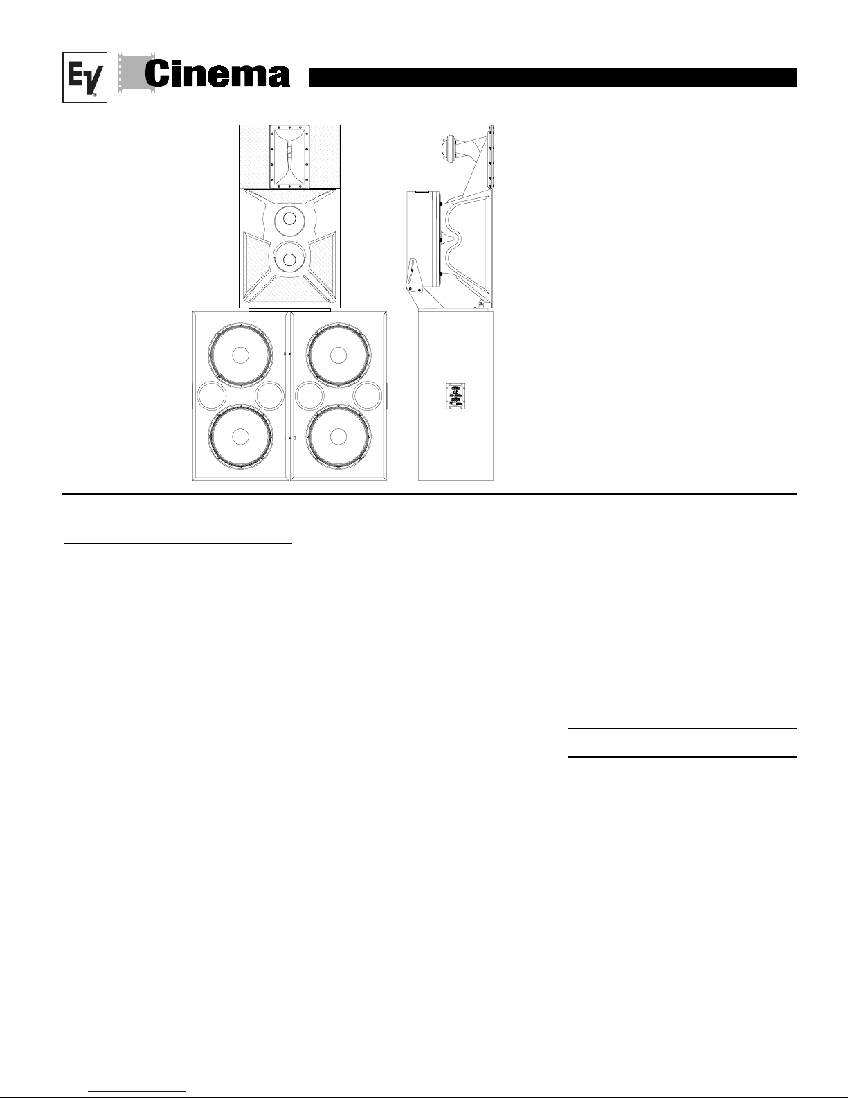
VariplexTM-XL
3-Way Screen System
· THX® approved*
· Patented high-frequency system
· Vari-Intense Technology for
smooth, even coverage
· Compact design for use in large
to small rooms
TM
TM
)
· Ring Mode Decoupling(RMD
provides greater Intelligiblity
· Digital Dynamics Capable
· Factory pre-assembled mid/high
unit
Description
The Electro-Voice Variplex
TM
-XL is designed specifically for use in ultra-high-fidelity cinema applications. The system is
®
THX
approved* and offers Electro-Voice
patented technologies. The V ariplex
TM
-XL is
a full three-way configuration that addresses
many performance issues not addressed in
other three-way designs. The V ariplex
employs ElectroVoice’s patented
TM
-XL
2
Vari Intense- (VI) variable-intensity low distortion
horn system. This design offers two fundamental advantages. The variable horn throat
impedance provides uniform sound pressure
levels over the entire auditorium. Conventional horn systems attempt to do the same
by aiming the center of the high-frequency/
mid-frequency horn toward the rear of the
room. This conventional approach wastes
fully one-half of the system energy and headroom, and radiates that wasted energy onto
the ceiling and walls, thus producing reflections that further degrade overall intelligibility and system clarity. The patented variable- intensity approach, on the other hand,
compensates for the natural phenomenon of
sound reduction with distance and produces
______________________
1
THX is a registered trademake of Lucasfilm Ltd.
* The Variplex-XL is THX approved for, screen to last row
distances, greater than 80 feet
2
U.S. Patent 5,020,630, Loudspeakers & Horn Therefor.
extremely uniform coverage for the entire
seating area. The same level of fidelity in
the front, middle and the back of the room is
achieved while substantially reducing reflected energy and consequently greatly improving tonal quality and intelligibility. The
advantages are twice the headroom and
greatly improved fidelity.
The Variplex
TM
-XL is also unique in that its
three-way design utilizes a bass/mid-bass/
high-frequency approach rather than a conventional bass mid-range/high-frequency
design. This mid-bass/high-frequency approach produces superior vocal clarity. Also
incorporated into the Variplex
Electro-Voice’s RMD
TM
RMD
,or Ring Mode Decoupling, employ-
TM
TM
-XL is
technology.
ees mechanical and acoustical equalization to resolve system resonances (or ringing modes) and frees electrical equalizers to
perform the job they were originally intended
to perform, that being room equalization and
correction of the spectral characteristics
inherent in the tranducers themselves. Prior
designs have frequently attempted to "resolve” loudspeaker design issues with electrical equalizers. RMD
TM
substantially im-
proves system transient detail and further
refines system clarity.
The unique performance enhancements and
system capabilities are ideally suited to the
high dynamic-range demands of digital material. When the pre-assembled HPKVariplex
Electro-Voice’s THX
TM
-XL is used in conjunction with
®
approved
subwoofers, the combination defines a new
standard for realism and total system accuracy.
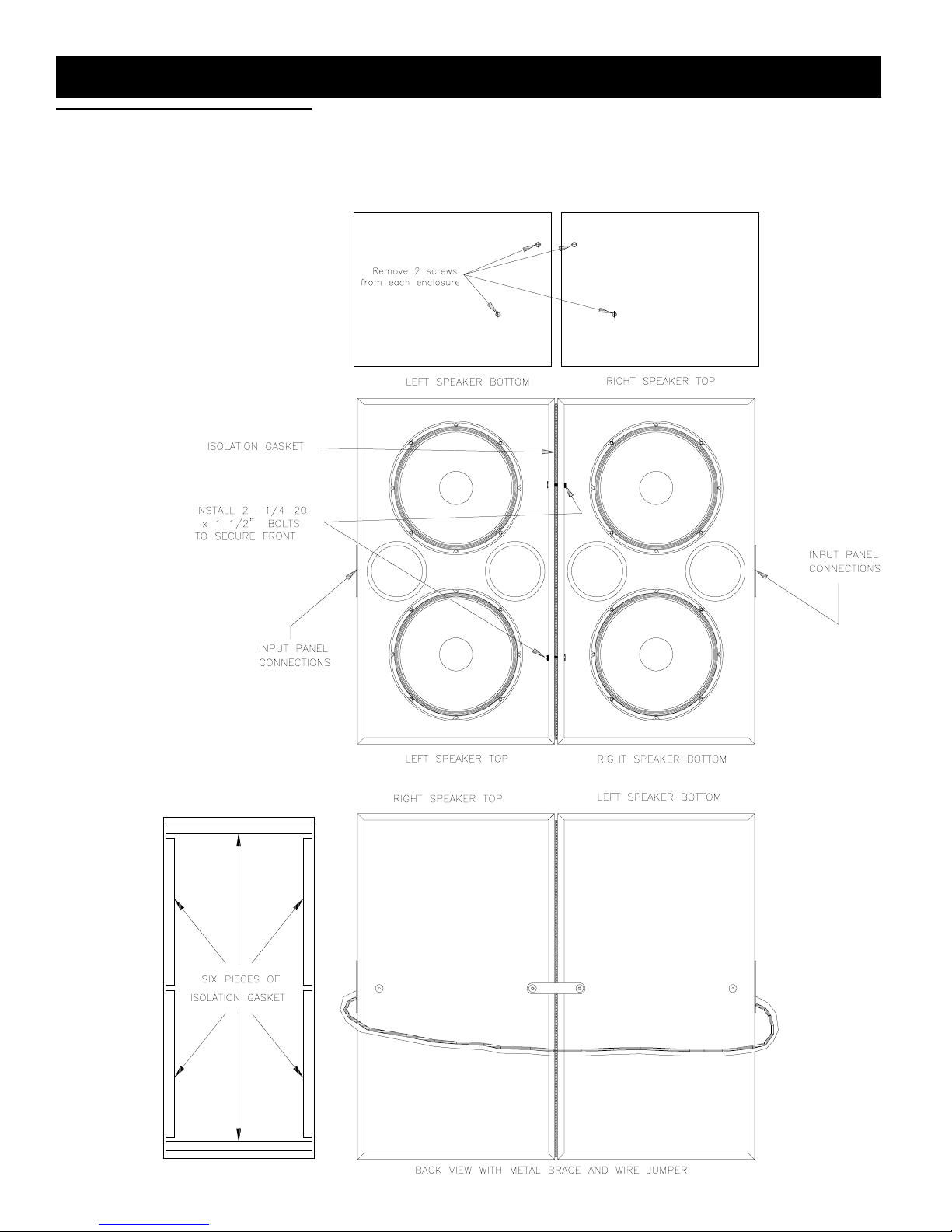
Low Frequency Assembly Instructions
Refer to Figures l and 2 for the following
The Low Frequency Unit comes shipped as
two pieces (2-TL606MXL's).
1. Turn one of the low frequency units upside down and the other is right side up, arrange as illustrated in figure 1.
2. Remove the isolation gasket stips from the
low frequency accesory bag (shipped with
the HPK-V ariplex
TM
-XL. Attach the strips to
the up-side down speaker as shown in figure 1.
3. Remove the locking brace the low frequency acessory bag and attach it to the back
of the unit right side up.
Page 2
V ariple x™- XL 3- Way Screen System
Figure 1—Low Frequency Speaker
Assembly
Variplex™ XL 3-Way Screen System
Page 3
V ariple x™-XL 3-W ay Screen System
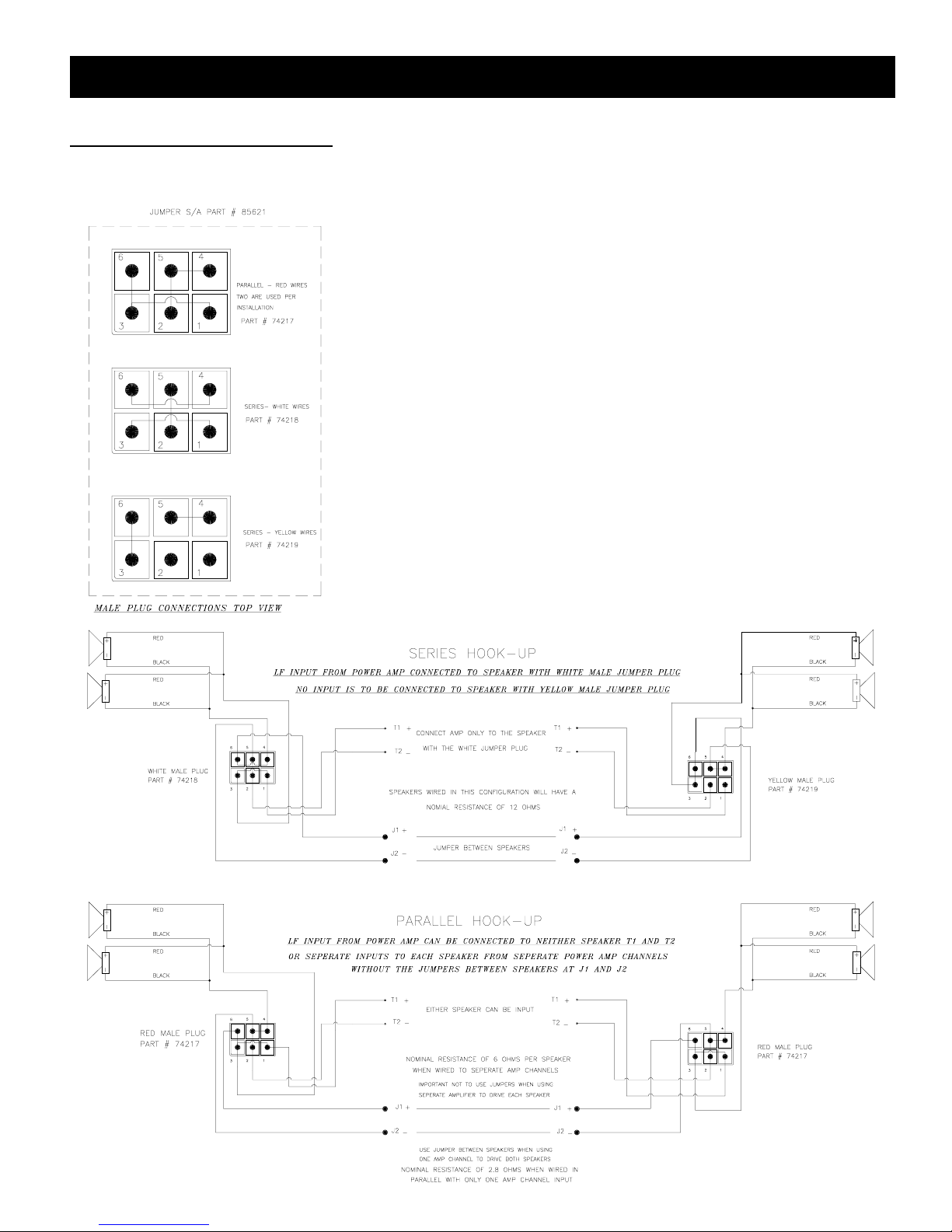
Figure 2—Low Frequency Wiring
Configuration
4. Slide to two units together, with the backs
almost touching and the front slightly appart.
Engage the brace to the other speaker and
tighten the bolt. Pull the front of the units
together. Pass the 1/4-20 x 1 1/2 inch bolts
through the holes opposite the T-nuts in each
of the enclosures front baffle inside edge.
(see figure 1) Tighten bolts unitl a 1/16 inch
remains between the two enclosures.
5. Now that the Low frequency units are attached, the input panels can be connected.
(See Figure 2 for referance) There are three
wiring configurations possible. The speakers maybe wired in Series with one amp
channel input or wired in Parallel with one
amp channel input. Finally they may be
wired seperately, each speaker on one amp
channel. (NOTE: Use red jumper plugs
but, do not us wire jumpers between J1
and J2 when using this particular configuration.)
Series wiring configuration: Connect J1 to
J1 and J2 to J2, using supplied wire jumper.
Select the supplied white jumper plug and
the yellow jumper plug. The white jumper
plug is to be installed on the speaker which
has T1 and T2 connected to the amplifier
source. The yellow jumper is installed on the
other speaker, for a nominal impedance of
12 ohms.
Parallel wiring configuration: Connect J1
to J1 and J2 to J2, using supplied wire
jumper. Select the two supplied red jumper
plugs and install one in each of the input
panels.
The amplifier source may be connected to
either input panel at T1 and T2, for a nominal impedance of 2.8 ohms.
Seperate wiring configuration: Do not con-
nect J1 to J1 amd J2 to J2. Select the two
supplied red jumper plugs and install one in
each of the input panels. The individual amplifier channels may be connected to each
of the input panels at T1 and T2 for indivdual
nominal impedances of 6 ohms.
Variplex™ XL 3-Way Screen System
Page 4

V ariple x™- XL 3- Way Screen System
Mid/HI Frequency Assembly
Instructions
Refer to Figures 3 for the following steps.
1. Remove four screws on top of the Low
frequency unit (see figure 3), two from each
of theTL606MXL enclosures Two of the
screws are 1 3/4" and will be replaced in the
same holes.
2. Set the mid/high sub-assembly on top of
the two TL606MXL's align the empty holes
on both TI606MXLs with the three slots of
the mid/high sub-assembly mounting board.
Reinstall the screws previously removed , being sure to install the longer two screws in
the back slot under the adjustment bracket.
3. Adjust the horizontal position by rotating the HPK-Variplex
Variplex™ XL 3-Way Screen System
TM
-XL and securely
tighten all the bolts so that the mid/high sub-
assembly does not inadvertently rotate.
4. Now loosen the vertical adjustment bolts
(see figure 3) just enough so the adjustment
guides will slide within the adjustment slot
and the bracket is allowed pivot. Adjust the
vertical angle, by tilting the mid/high subassembly,
which will slide the adjustment
bolts along the slot as shown in figure 3.
5. The aiming point of the mid/high subassembly horn seperates the Mid-frequency
section from the Hi-frequency section, (see
figure 7). The system is approximately positioned 2/3 the way up the screen (see figure 7), then tilted vertically to align the aiming point two feet above the head of the person sitting in the last seat of the theater. (See
figure 7) Tighten the vertical adjustment
bolts, so that the mid/high sub-assembly does
not inadvertently tilt.
Figure 3—Mounting the HPK-VARIPLEXTM-XL (pre-assembled mid/high unit)
Note:Additional tilting may be necessary
depending on the slope of the seating area.
Do not tilt the aiming point below 2ft.
above the last person sitting in the last seat
of the theater . Sound pressur e levels drop
off drastically above zero on axis.
Crossover Equalization
The Electro-Voice Dx38 digital electronic
crossover system may be used to crossover
equilize and set time delay for the
VariplexTM-XL. Figure 6 is a typical transfer curve based on the indivdual frequency
responses of its components as shown in figure 4. Further data on these setting may be
obtained by contacting Electro-V oice for information on specific Dx38 presets.
Page 5

V ariple x™-XL 3-W ay Screen System
Frequency Response
Figure 5 shows V ariplex
TM
-XL frequency response with presets of the Electro-Voice
Dx38 digital electronic crossover system processor (see Crossover Equalization section).
The measurement was made with a swept
sine-wave signal, 4 volts at 500 Hz, in an
anechoic (echoless) environment. The microphone was at a distance of 3.048m (10 ft),
on an axis with the aiming pointof the Mid/
Hi-frequency unit. Figure 5 shows the frequency response of the individual sections
Figure 4—VARIPLEX
TM
-XL Typical Frequency Response of Low / Mid and High Frequency Sections Alone (swept sine-wave
of the Variplex
TM
-XL, measured under the
same conditions but at 1 watt at 2 meters. The
results of which were then normalized to 1
watt/1 meter at 500Hz.
Uniform Limited Warranty Statement
Electro-Voice products are guaranteed
against maltunction due to defects in
materials or workmanship for a specified
period, as noted in the individual productline statement(s) below, or in the individual
product data sheet or owner’s manual,
beginning with the date of original pur-
chase. If such maiflinction occurs during
the specified period, the product will be
repaired or replaced (at our option) without
charge. The product will be returned to the
customer prepaid.
Exclusions and Limitations: The Limited
Warranty does not apply to: (a) exterior
finish or appearance; (b) certain specific
items described in the individual productline statement(s) below, or in the individual
product data sheet or owner’s manual; (c)
malfunction resulting from use or operation
of the product other than as specified in the
product data sheet or
input, anechoic environment, (normialized repsonse, from 1 watt, 2 meters from the horn baffle, at 600Hz, with the Microphone
axis coincident with the aiming point. (Midway between Mid-Frequency horn and High Frequency horn)
Variplex™ XL 3-Way Screen System
Decibels (dB)
Frequency
Figure 5—VARIPLEXTM-XL System Typical Frequency Response with DX38 (Digital Speaker System Precessor) Presets:
Swept sine -wave input, under anechoic environment, (normialized repsonse, for 4 volts, 10 feet at 600hz, with the
Microphone axis coincident with the aiming point. (Midway between Mid-Frequency horn and High Frequency horn)
Decibels (dB)
Frequency
Page 6

V ariple x™- XL 3- Way Screen System
owner’s manual; (d) malfunction resulting
from misuse or abuse of the product; or (e)
malfunction occurring at any time after
repairs have been made to the product by
anyone other than EVI Audio Service or
any of its authorized service representatives.
Obtaining Warranty Service: To obtain
warranty service, a customer must deliver
the product, prepaid, to EVI Audio Service
or any of its authorized service representatives together with proof purchase of the
Figure 6—Transfer function of the
DX38 digital prcessor for the
TM
VARIPLEX
-XL
Variplex™ XL 3-Way Screen System
product in the form of a bill of sale or
receipted invoice. A list of authorized
service representatives is available from
EVI Audio Service at 600 Cecil Street,
Buchanan, MI 49107 (800/234-6831 or
FAX 616/695-4743).
Other Rights: This warranty gives you
specific legal rights, and you may have
other rights which vary from state to state.
For warranty repair, service information,
or a listing ofthe repair facilities nearest
you, contact the service repair departent at:
616/695-6831 or 800/685-2606.
For technical assistance, contact Technical
Support at 800/234-6831 or6 I 6/695-6831,
M-F,8:00 a.m.to 5:00p.m. Eastern time.
Specifications subject to change without notice.
Decibels (dBu)
Figure 7—Aiming the VARIPLEXTM-XL
Frequency
Page 7

V ariple x™-XL 3-W ay Screen System
Specification
Frequency response: (See Figure-5)
40 Hz - 20,000 Hz
Power Handling:
Low Frequency: 1600 watts continuous
(6400 watts peak)
Mid Bass: 500 watts continuous
(2000 watts peak)
High Frequency: 60 watts continuous
(240 watts peak)
Nominal Directivity:
o
Horizontal: 90
short axis/600 long axis
Vertical (from system geometric axis):
o
up at 6dB 50o down at -18 dIB
5
System Impedance:
Bass: 2 x 6 ohms nominal
See figure 2 for minimum
Mid Bass: 4 ohms nominal
3.6 ohms minimum
High Frequency: 16 ohms nominal
10.3 ohms minimum
Sound Pressure at 1Watt, 1Meter Input:
(See Figure -4)
LF 40Hz to 300Hz (average)
104 dB
MF 300 to 1,200Hz (average)
109 dB
HF (1,500Hz to 7,000Hz (average):
112 dB
Crossover Frequencies: (See Figure -6)
LF/MF
300 Hz (24-dIB-per-octave Linkwitz-Riley)
MF/HF
1,560 Hz (24-dIB-per-octave LinkwitzRiley)
High-Pack Mounting Holes:
Five, 1/4-20 bolts, Allowing for smooth
horizontal adjustment and secure
attachment of the pre-assemb led
high-pack.
Material:
Low frequency enclosure is 9-ply
plywood,Black textured painted
enclosure.
Mid/Hi frequency Horn is black
gelcoated fiber glass, with a MFD black
painted dual 10' speaker enclosure
Input Connectors:
#10 screw terminals for bass, mid bass and
high frequency
Dimensions Low Frequency:
System uses two TL606MLX speakers
Single Unit Dimensions:
Height: (100 cm) 39.5 in
Width: (57.2 cm) 22.5 in.
Depth: (44.8 cm) 17.62 in.
Weight: (49.0 kg) 108 lb
Shipping Weight: (54.4 kg) 120 lb
Mid Bass/High Frequency:
Height: (cm) 43.55 in.
Width: (59.7 cm) 23.5 in.
Depth: ( 51.13cm) 20.13 in.
Weight: (39.46 kg) 87.0 lb
Shipping Weight: (66.9 kg) 147.5 lb
Total System Assembled Dimensions:
Height: (209 cm) 8832.3 in.
Width: (115 cm) 45.3 in.
Depth: (51.13cm) 20.13 in.
Weight: (138.35 kg) 305 lb
Variplex™ XL 3-Way Screen System
Page 8

Variplex™ XL 3-Way Screen System
V ariple x™- XL 3- Way Screen System
CINEMA—Speaker Systems Part Number535296—9934
600 Cecil Street, Buchanan, MI 49107
800/234-6831, 616/695-6831, 616/695-1304 Fax
©EVI Audio 1999 • Litho in U.S.A.
 Loading...