

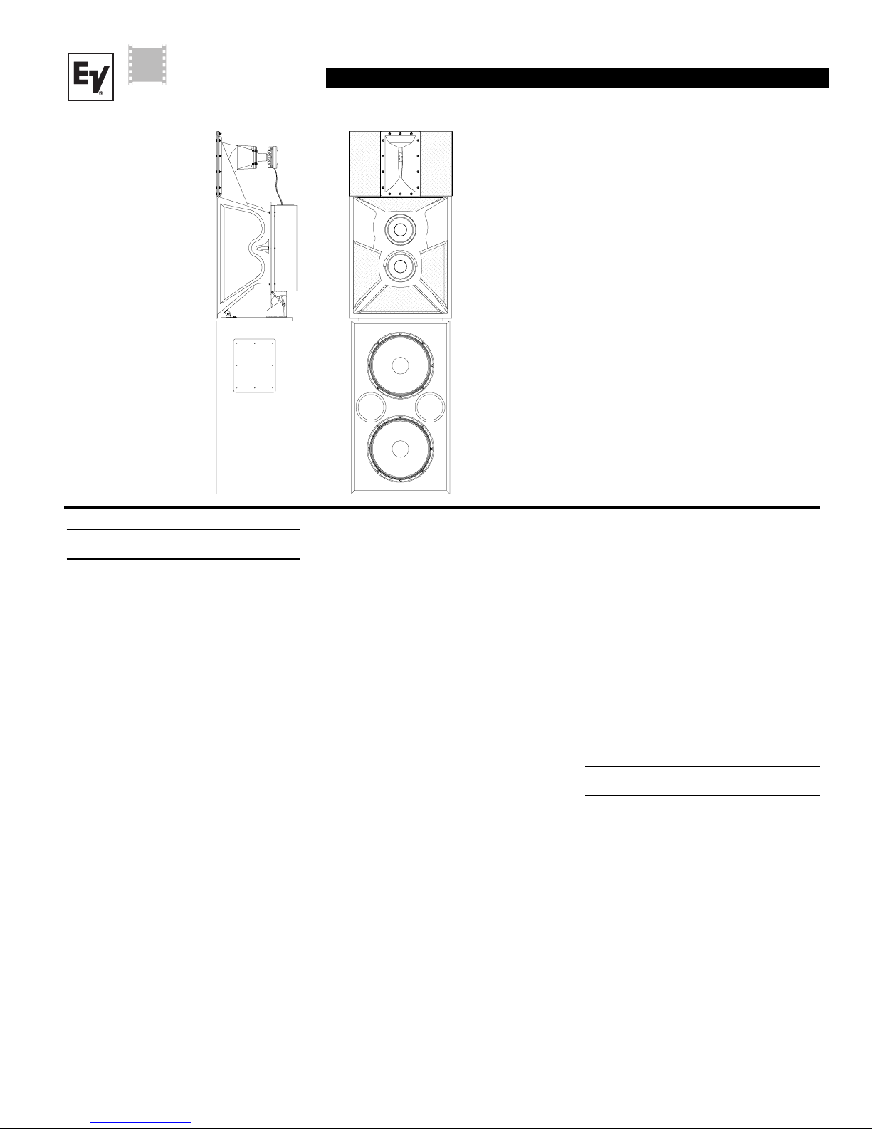
Electro-Voice VARIPLEX-B Quick Start Manual
Cinema
Systems
R
TM
V ARIPLEX
Three-Way Screen System
• Vari-Intense® Technology for
smooth, even coverage
• Passive mid/high design allows
for biamped operation
• Compact design for limited
behind-the-screen space
• Ring-Mode Decoupling (RMD
provides greater Intelligibility
• Digital Dynamics Capable
• Factory pre-assembled mid/
high unit
TM
-B
TM
)
Description
The Electro-Voice Variplex
specifically for use in ultrahigh-fidelity
cinema applications. The system offers
Electro-Voice patented technology. The
Variplex
that addresses many performance issues not
addressed in other three-way designs. The
Variplex
ented
horn system. This design offers two fundamental advantages. The variable horn throat
impedance provides uniform sound pressure
levels over the entire auditorium. Conventional horn systems attempt to do the same
by aiming the center of the high-frequency/
mid-frequency horn toward the rear of the
room. This conventional approach wastes
fully one-half of the system energy and headroom, and radiates wasted energy onto the
ceiling and walls, thus producing reflections
that further degrade overall intelligibility and
system clarity. The patented variable- intensity approach, on the other hand, compensates for the natural phenomenon of sound
reduction with distance and produces
______________________
1
TM
-B is a three-way configuration
TM
-B employs Electro-Voice’s pat-
1
Vari Intense® (VI) variable-intensity
U.S. Patent 5,020,630, Loudspeakers & Horn Therefor.
TM
-B is designed
extremely uniform coverage for the entire
seating area. The same level of fidelity in
the front, middle and the back of the room is
achieved while substantially reducing
reflected energy and consequently greatly
improving tonal quality and intelligibility.
The advantages are twice the headroom and
greatly improved fidelity.
The Variplex
three-way design utilizes a bass/mid-bass/
high-frequency approach rather than a conventional bass mid-range/high-frequency
design. This mid-bass/high-frequency approach produces superior vocal clarity. Also
incorporated into the Variplex
Electro-Voice’s Ring-Mode Decoupling
(RMD
mechanical and acoustical equalization to
resolve system resonances (or ringing
modes) and frees electrical equalizers to perform the job they were originally intended
to perform, that being room equalization and
correction of the spectral characteristics
inherent in the tranducers themselves. Prior
designs have frequently attempted to "resolve” loudspeaker design issues with electrical equalizers. RMD
proves system transient detail and further
refines system clarity.
TM
-B is also unique in that its
TM
-B is
TM
). Ring-Mode Decoupling employs
TM
substantially im-
The compact design of the VariplexTM-B allows
the system to be used even when behind-thescreen space is limited. Compact design can
also provide a cost savings by allowing the
addition of extra seating.
The unique performance enhancements and
system capabilities are ideally suited to the
high dynamic-range demands of digital material. When the Variplex
junction with Electro-Voice’s subwoofers, the
combination defines a new standard for
realism and total system accuracy.
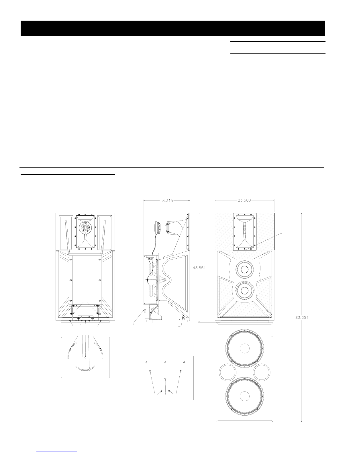
Mounting Instructions
Refer to Figures l and 2 for the following
steps.
1. Remove five screws on top of the
TL606DMT (see figure 2), the two farthest from the front of the enclosure are 1
3/4" and will be needed be replaced in
the same holes.
2. Set the mid/high subassembly on top of
the TL606DMT align the empty holes on
the TL606DMT with the three slots and
center pivot hole of the mid/high subassembly mounting board. Reinstall the
screws previously removed, being sure
to install the longer two screws in the
TM
-B is used in con-
VARIPLEX
TM
-B
back slot under the adjustment bracket.
3. Adjust the horizontal position and securely tighten all the bolts so that the mid/
high subassembly can not inadvertently
rotate.
-B
4. Now loosen the two vertical adjustment
TM
bolts just enough so the adjustment
guides will slide within the adjustment
slot. Adjust the vertical angle, by tilting
VARIPLEX
the mid/high subassembly,
which will
slide the adjustment bolts along the slot
as shown in figure 1.
Figure 1— Mounting the
TM
HPK-Variplex
-B (pre-assembled mid/
high unit)
5. The aiming point of the mid/high subassembly horn separates the mid-frequency
section from the high-frequency section,
(see figure 1). For proper imaging, this
point should be positioned just above the
vertical center line of the screen (typically 0.6 of the overall screen height),
(see figure 2). Then tilt vertically to align
with the head of the person in the last
seat of the theater, (See figure 2), and
tighten the vertical adjustment bolts, so
the mid/high subassembly can not inadvertently tilt backwards.
Frequency Response
Figure 4 shows the Variplex
TM
-B frequency
response with a swept sine-wave signal,
4 volts at 500 Hz, in an anechoic (echo free)
environment. The microphone was at a distance of 3.0 m (10 ft), on an axis with the aiming point of the mid/high-frequency unit.
Loosen for
vertical
adjustment
Loosen for horizontal
adjustment
Back Edge of the Mid/High
sub-assembly Baseboard
(HPK-Variplex-B)
Use longer bolts
in back slot when
mounting the
HPK-Variplex-B
Remove Only These Bolts
Bolt Layout for the TL606DMT
Aiming
Point
Pivot Point
Front of TL606DMT
2
 Loading...