

Page 1
e
EleclroVoice
Commercial
Microphones
US621L
US622L
DYNAMIC
MICROPHONES
•
Touch
•
7-foot,
bare-wire
•
US621l:
US622l:
noise-cancelling
DESKTOP
to
talk
5-conductor
termination
Omnidirectional
Cardioid,
cable
with
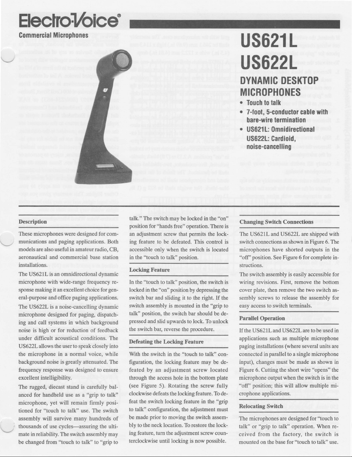
Description
These microphones were designed for com-
munications and paging applications. Both
models are also useful in amateur radio, CB,
aeronautical and commercial base station
installations.
US621L is an omnidirectional dynamic
The
microphone with wide-range frequency response making it an excellent choice for general-purpose and office paging applications.
US622L is a noise-cancelling dynamic
The
microphone designed for paging, dispatching and call systems in which background
of
noise is high or for reduction
under difficult acoustical conditions. The
US622L allows the user to speak closely into
the microphone in a normal voice, while
background noise is greatly attenuated. The
frequency response was designed to ensure
excellent intelligibility.
The rugged, diecast stand is carefully balanced for handheld use as a
microphone, yet will remain firmly positioned for
assembly will survive many hundreds
thousands
mate in reliability. The switch assembly may
be changed from
"touch to talk" use. The switch
of
use cycles--assuring the ulti-
"touch to talk" to "grip to
feedback
"grip to talk"
of
talk." The switch may be locked
position for "hands free" operation. There is
an adjustment screw that permits the locking feature to be defeated. This control is
accessible only when the switch is located
"touch to talk" position.
in the
Locking
In the "touch to talk" position, the switch is
locked in the
switch bar and sliding it to the right.
switch assembly is mounted in the
talk" position, the switch bar should be depressed and slid upwards to lock.
the switch bar, reverse the procedure.
Defeating the Locking
With the switch
figuration, the locking feature may be defeated by an adjustment screw located
through the access hole in the bottom plate
(see Figure 5). Rotating the screw fully
clockwise defeats the locking feature.
feat the switch locking feature in the
to
be made prior
bly to the neck location.
ing feature, tum the adjustment screw counterclockwise until locking is now possible.
Feature
"on" position by depressing the
Feature
in
the "touch to talk" con-
talk" configuration, the adjustment must
to
moving the switch assem-
To
in
the "on"
If
the
"grip to
To
unlock
To
de-
"grip
restore the lock-
Changing
The
switch connections as shown in Figure
microphones have shorted outputs in the
"off"
structions.
The switch assembly is easily accessible for
wiring revisions. First, remove the bottom
cover plate, then remove the two switch assembly screws to release the assembly for
easy access
Parallel
If
the US621L and US622L are to be used
applications such as multiple microphone
paging installations (where several units are
connected in parallel to a single microphone
input), changes must be made as shown
Figure
microphone output when the switch is in the
"off"
crophone applications.
Relocating Switch
The microphones are designed for
talk" or "grip to talk" operation. When received
mounted on the base for
Switch Connections
US621L and US622L are shipped with
6.
The
position. See Figure 6 for complete in-
to
switch terminals.
Operation
in
in
6.
Cutting the short wire "opens" the
position; this will allow multiple mi-
"touch to
from the factory, the
"touch to talk" use.
switch
is
Page 2
US6Z 1 Land
US6ZZL
Dynamic
Microphones
H desired, the switch may be relocated with-
out wiring changes to the neck
phone for "grip to talk" operation.
To relocate the switch, proceed as follows:
Remove the black plastic cover from the
~
1.
c:
neck
of
o
..c
~
'E
S
...J 3.
N
N
\0
V'l
::l
"0
...J
~
V'l
::l
one end with a flat blade. This will expose
0.
o
...
the
u
cover, as it will be needed for the opening
u
on the base
Remove two screws and the cover plate
~
2.
c:
from the bottom
Slip the strain-relief spring from slot.
4. Remove the two screws located in the neck
of
Gently lift switch assembly away from
5.
c:
microphone housing.
~
6. Thrn the entire switch assembly so the top
surface
the microphone with wires protruding
from the bottom
7. Secure switch assembly in the neck with
the two screws.
8. Check the action
that all wires are properly seated and have
not become entangled in the switch assem-
bly.
9. Loop the cable around the bass located in
the housing base and seat the strain-relief
spring at the rear
Secure the bottom plate with two screws.
Place the black plastic cover into the open-
10.
ing
bar was previously removed) by inserting
the two tabs into the opening and snapping cover into position.
Architects'
The model
omnidirectional, dynamic type with uniform
frequency response from
model
cancelling dynamic type with uniform frequency response from 125-5,000 Hz. The microphone output impedance shall be specified
150 ohms. The output level shall be
(0
dB=lm
case shall be
shall include a diecast zinc table stand inte-
the microphone by gently lifting
"grip to talk" switch opening. Save the
of
the microphone.
of
the microphone.
the microphone.
of
the switch bar faces the front
of
the switch.
of
of
on
the base (from which the red switch
and
Engineers'
US621L microphone shall be an
US622L microphone shall be a noise-
WIlO dynes/cm
of
Cycolac and diecast zinc, and
of
the switch to ensure
the microphone base.
Specifications
100-9,000 Hz. The
2
).
The microphone
the micro-
-57
dB
gral with the microphone case. The assembly
mm
shall be 246.1
(4.5 in.) wide x 122.2
A
DPDT
switch shall be provided, one sec-
tion
of
which shall normally short circuit the
transducer when switch is in "off" position.
(Provisions shall be made for connecting the
normally open mode in
ing the microphone circuit for
for multiple microphone paging installations.)
A second switch section shall be provided
with the capability to function either in an
tronic switching mode or for operation
ternal relay. A locking feature shall be provided by means
"on"
position. A 2.13 m (7 ft) black plastic-
in
jacketed, five-conductor, two-shielded cable
shall be furnished. The finish
stand and microphone shall be nonreflecting
blue-black. Net weight shall be 822 g
of
13 oz).
The Electro-Voice commercial microphones
US621L and US622L are specified.
Unifonn
Electro-Voice products are guaranteed against
malfunction due to defects in materials
workmanship for a specified period, as noted
in
below,
or
of
curs during the specified period, the product
will be repaired
without charge. The product will be returned
to the
Limitations:
apply to: (a) exterior finish or appearance; (b)
certain specific items described in the
vidual product-line statement(s) below, or in
the individual product data sheet
manual; (c) malfunction resulting from use or
operation
fied
manual; (d) malfunction resulting from misuse
tion occurring at any time after repairs have
been made to the product by anyone other than
EVI Audio
service representatives.
Limited
the individual product-line statement(s)
or
in the individual product data sheet
owner's
original purchase.
customer
of
in
the product data sheet
or
abuse
(9.69 in.) high x 114.3
mm
(4.81 in.) deep.
"off"
position and clos-
of
which switch may be locked
Warranty
manual, beginning with the date
If
such malfunction oc-
or
replaced (at
prepaid.
The Limited Warranty does not
the product other than as speci-
of
the product;
Service
or
any
Obtaining
Exclusions
or
of
mm
"on"
position
elec-
of
ex-
of
the integral
(lib,
Statement
our
option)
and
indi-
or
owner's
or
owner's
(e) malfunc-
its authorized
Warranty
Service: To obtain warranty service, a customer must deliver the product, prepaid, to
EVI Audio
service representatives together with proof
purchase
sale
service
EVI Audio Service at 600 Cecil Street, Bucha-
nan,
616/695-4743).
tial
replacement and return
the only remedies provided to the customer.
Electro-Voice shall not
cidental
ing, without limitation, injury to persons
property
allow the exclusion or limitation
or consequential damages
tation
Other
cific legal rights, and you may 'also have other
rights which vary from state to state.
Electro-Voice
anteed against malfunction from any cause for
two (2) years from the date
chase. In addition, the Limited Warranty for
or
the acoustic system contained in these microphones shall apply for the life
defined as a period
date that the manufacture
crophone has been discontinued. Any and all
active electronics incorporated in these microphones are guaranteed against malfunction due
to defects in materials
period
nal purchase. The Limited Warranty does not
extend to cables, cable connectors, or switches.
Additional details are included in the Uniform
Limited Warranty statement.
For warranty repair, service information, or a
listing
tact
616/695-6831
For
Support at 800/234-6831 or 616/695-6831, MF, 8:00
time.
Specifications subject to change without notice.
Service
of
the product in the form
or
receipted invoice. A list
representatives
MI
49107
Damages
or
consequential
or
or
exclusion
Rights: This warranty gives you spe-
of
three (3) years from the date
of
the repair facilities nearest you, con-
the
service
technical
a.m. to 5:00 p.m. Eastern Standard
or
any
of
is
available
(800/234-6831
Incidental
Excluded:
loss
of
Wired
often
repair
or
800/685-2606.
and
Product repair
to
the
be
liable for any indamages
use. Some states do not
so
may
not apply to you.
Microphones
of
(10) years from the
of
the specific mi-
or
workmanship for a
department
assistance, contact Technical
its authorized
of
a bill
of
authorized
from
or
FAX
Consequen-
customer
of
the above limi-
original pur-
of
the product,
are
includ-
incidental
are guar-
of
origi-
at:
of
of
or
or
Page 3

Figure
l-US621L
US6Z I Land
Frequency Response
US6ZZL
Dynamic
Microphones
Figure
2-US622L
Frequency Response
+10
·10
+10
·10
21.
CLOSE
TALK
RESPONSE
1.1
'"
j
..
1.
III
III
FREQUENCY IN HERTZ
CLOSE
TALK
RESPONSE
I.
1/4
INCH
~
./
_
1/4
INCH
,
-
V'\
,,-
~
,
V
1\
,
Figure
270·
3-US621L
"I-1-+-+-+-+--i
Polar Response
0°
1--+-+-+-+-+-190°
180°
lePEA
DM8ION
21.
I.
..
1.
III III
FREQUENCY IN HERTZ
_
Figure
4-US622L
270"l-t-+Irt+-+-+-;
Polar
Response
----
180°
-VERTICAL
l-H--+-:'-fH--l9O°
HORIZONTAL
Page 4

US62 I Land
US622L
Dynamic
Microphones
0/)
CI)
c:
o
..c:
a.
o
...
u
~
.~
E
~
c:
~
...J
N
N
\l)
V')
::l
'"0
c:
~
...J
FIGURE
View
5-US621L/US622L
Et
~
lADE
II
U.S.A
TURN SCREW CLOCKWISE TO
Bottom
US621L
DYNAIlIC IIICROPHONE
LOW
....
DoUICI:
~.
.
..--,_U.aA.
--
DEFEAT LOCKING FEATURE
FIGURE
Diagram
CUT THIS LEAD
L()'Z
DUTPUT
RED
GREEN
I
I
-------
WHITE
6--US621L/US622L
10
DPEN
UNE
IN OFF
POsmON
-1-
--
~
Wiring
...
::
III
...
i
~
o
SPECIFICATIONS
US621UUS622L:
Dynamic
Frequency Response,
US621L (see Figure 1):
100-9,000 Hz
US622L (see
Polar
Pattern,
US621L (see
Omnidirectional
US622L (see Figure 4):
Cardioid, noise-cancelling
COMMERCIAL MICROPHONES
Figure
125-5,000 Hz
Figure
2):
3):
Impedance, US621UUS622L:
150 ohms
Output
Level, US621UUS622L:
-57
Case Material, US621UUS622L:
Finish, US621UUS622L:
Dimensions, US621UUS622L,
dB (0 dB = 1
Pressure-cast zinc and Cycolac
Bluelblack
Height:
146
Width: 114.3
Depth: 122.2
.1
mm
(9.
mm
(4.5 in.)
mm (4.
mW/I0
69
in
.)
81
in
dynes/em')
.)
Net Weight, US621UUS622L:
822 g
(lIb, 13
Switch, US621UUS622L:
Leaf, DPDT, switches external circuit and
shorts or opens mike in "off" position
Cable, US621UUS622L:
2.13 m (7 ft) long, 5-conductor, 2-shielded,
vinyl jacket, black
8
oz)
ElecfroVoice
600 Cecil Street , Buchanan, MI 49107
616/695-6831,616/695-1304 Fax
©EVI Audio 1997 • Litho in U.S.A. Part Number
532591-9744
 Loading...