

Page 1
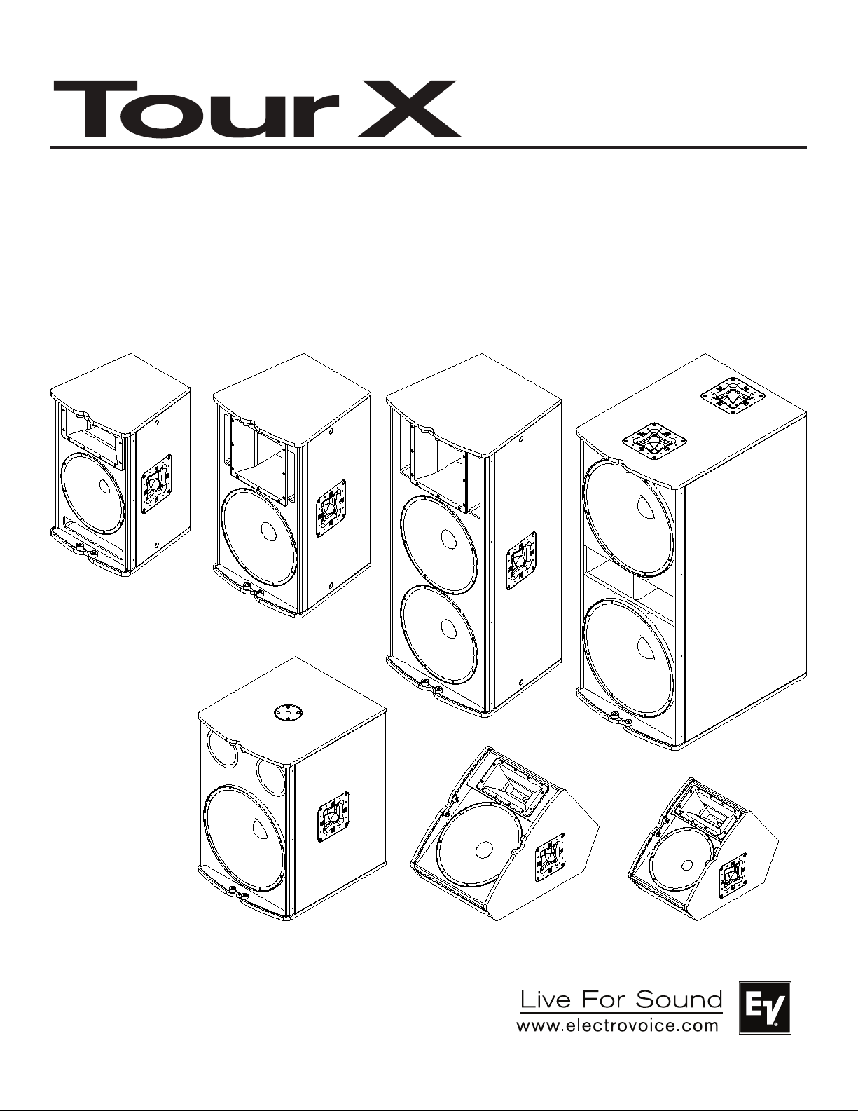
Tour X Series
Loudspeaker
Owner’s Manual
TX1122
TX1152
TX2152
TX1181
TX2181
TX1122FM
TX1152FM
Electro-Voice® Tour X Owner’s Manual
Page 2
Important Safety Instructions
1. Read these instructions.
2. Keep these instructions.
3. Heed all warnings.
4. Follow all instructions.
5. Do not use this apparatus near water.
6. Clean only with a dry cloth.
The lightning flash with arrowhead symbol, within an equilateral
triangle is intended to alert the user to the presence of uninsulated “dangerous voltage” within the product’s enclosure that
may be of sufficient magnitude to constitute a risk of electric
shock to persons.
The exclamation point within an equilateral triangle is intended
to alert the user to the presence of important operating and
maintenance (servicing) instructions in the literature accompanying the appliance.
The asterisk within an equilateral triangle is intended to inform
the user to necessary installation or removal instructions regarding equipment or hardware use relating to the system.
Tour X Series Owner’s Manual
Thank you for choosing the Electro-Voice® Tour X series loudspeaker system. Please take time to con-
sult this manual so that you can understand all the features built into your EV system and fully utilize all its
performance capabilities.
Table of Contents
Important Safety Instructions ...........................................................................................................................................1
Tour X Series Owner’s Manual ........................................................................................................................................1
Safety First ..........................................................................................................................................................................2
Description ..........................................................................................................................................................................3
General System Features .................................................................................................................................................3
Suspending TX1122, TX1152, and TX2152 ...............................................................................................................3
Rotating the Horn on TX1152 and TX2152 .................................................................................................................7
Rotating the Logo ...............................................................................................................................................................8
TX-W1 Wheel Kit for TX1181 and TX2181 ................................................................................................................9
Specifications ................................................................................................................................................................... 10
Recommended Configurations ..................................................................................................................................... 12
Notes .................................................................................................................................................................................. 14
1
Electro-Voice® Tour X Owner’s Manual
Page 3
Safety First
Suspension: The Electro-Voice® TX1122, TX1152, and TX2152 have threaded points that can be used
for suspension. Please consult pages 3-6 on properly suspending Tour X models prior to installation.
WARNING: Suspending any object is potentially dangerous and should only
be attempted by individuals who have a thorough knowledge of the techniques and regulations of suspending objects overhead. Electro-Voice®
strongly recommends that Tour X speakers be suspended taking into account all current national, federal, state and local regulations. It is the responsibility
of the installer to ensure that all loudspeakers are safely installed in accordance
with all such regulations. If Tour X loudspeakers are suspended, Electro-Voice®
strongly recommends that the system be inspected at least once a year. If any sign
of weakness or damage is detected, remedial action should be taken immediately.
Any hardware used to suspend a Tour X loudspeaker that is not associated with
Electro-Voice® is the responsibility of others.
Stand Mount: The Electro-Voice® TX1122 and TX1152 include 1-3/8” stand mounts for use with tripod
stands. Check the specifications of the speaker stand to be certain it is capable of supporting the weight
of the speaker. Place the speaker stand on a flat, stable surface and be sure to fully extend the legs of the
stand. Do not try to make the stand “taller” and compromise its structural integrity. Do not attempt to suspend more than one speaker on a stand designed for a single speaker. Unless you are confident that you
can safely handle lifting the weight of the speaker onto the stand, ask another person to help you place it.
Route cables and position the stand so that performers, production crew and audience members will not
trip over the stand or cables and pull the speaker system over. Secure the cables with wire ties or tape
whenever possible.
Ground Stack: The Electro-Voice® TX2152 can be vertically stacked on a TX2181 to elevate the horn
above the audience. Unless you can safely lift the weight of the loudspeaker on to the ground stack, have
another person to help you place it. The ground stack should be placed on a solid, level surface. When
using subs on a surface that is hard or slick, take precautions to prevent the stacks from “walking”. When
using a ground stack in windy outdoor conditions, when the surface is slippery, or when in adverse conditions, Electro-Voice® recommends using a ratchet strap to secure the speakers.
Hearing Exposure: Electro-Voice® Tour X loudspeakers are capable of producing sound pressure levels sufficient to produce permanent hearing damage. Caution should be taken to avoid prolonged exposure to sound pressure levels exceeding 90 dB.
Moisture: Electro-Voice® does not recommend using Tour X loudspeakers in the rain or in high moisture
environments without protection.
Electro-Voice® Tour X Owner’s Manual
2
Page 4
Description
The Electro-Voice® Tour X professional loudspeakers are a unique and highly-functional package of pro
audio performance, versatility and aesthetics. Many of the design features are taken from EV’s many years
of experience in designing transducers and loudspeaker systems for high quality concert touring applications. The TX1122, TX1152, and TX2152 are multipurpose full-range loudspeakers that are equally
suited for portable and fixed installation applications. The TX1181 and TX2181 subwoofers are designed
for low frequency reinforcement of the full-range loudspeakers. The TX1122FM and TX1152FM are
purpose-built vertical floor monitors with (patent pending) Signal Synchronized Transducers (SSTTM) for
small to medium sized stages.
General System Features
· Low distortion, high excursion SMX and EVS woofers
· DH3 and ND2 compression drivers mated to Constant DirectivityTM horns
· Lightweight and durable enclosures with EVCoat
· High strength, 16GA steel “backbone” design grilles with rotatable logos
· High order crossovers with equalization and HF protection
· Dual NL4 input connectors
· Multi grip handles
· High sensitivity and power handling
· (6) 3/8” threaded points for eyebolt suspension (TX1122, TX1152, and TX2152 only)
· Signal Synchronized TransducersTM (TX1122FM and TX1152FM only)
TM
Suspending TX1122, TX1152, and TX2152
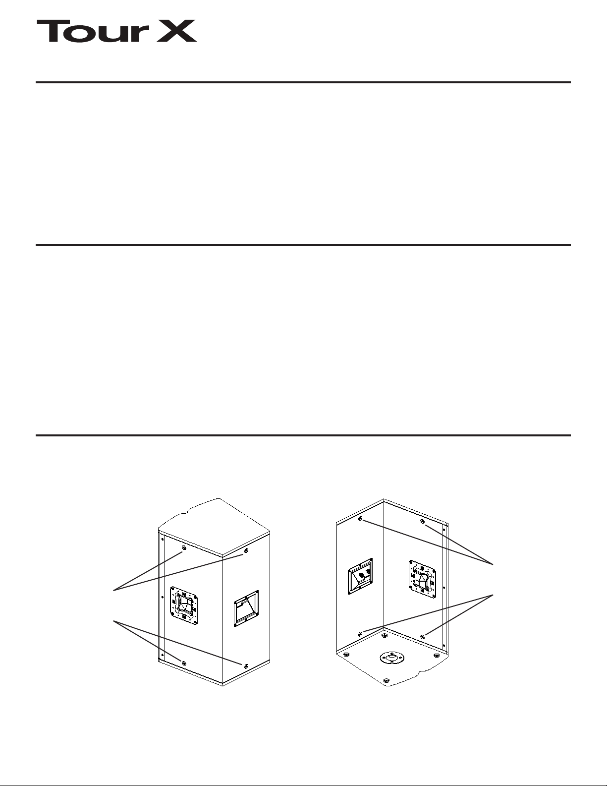
The TX1122, TX1152, and TX2152 enclosures have (6) 3/8” threaded points; (3) points on the top of the
enclosure and (3) points on the bottom (Figure 1). Forged shoulder eyebolts that are rated for overhead
suspension may be used to suspend an individual loudspeaker, such as the EBK-1 accessory.
Top Suspension
Points
Top Suspension
Points
Bottom Suspension
Points
3
Figure 1a:
TourX Suspension Points
(Right-Top View)
Figure 1b:
TourX Suspension Points
(Left-Bottom View)
Electro-Voice® Tour X Owner’s Manual
Bottom Suspension
Points
Page 5
Suspending TX1122, TX1152, and TX2152 (cont’)
Prior to use, inspect the suspension point(s) and associated hardware for any cracks, deformations,
broken welds, corrosion, missing or damaged components which could reduce the suspension point(s)
strength. Replace any damaged hardware. Never exceed the limitations or maximum recommended load
intended for the suspension point(s). As an added safety measure, it is suggested that the user install an
extra suspension point back to the building structural supports. This redundant safety point should have
as little slack as possible (less than one inch is preferable). Prior to each use, inspect the loudspeaker
enclosures for any cracks, deformations, missing or damaged components, which could reduce enclosure
strength. Replace any loudspeaker systems that are damaged or missing hardware.
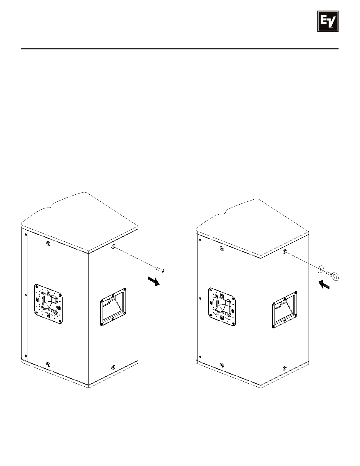
To install the eyebolts, remove the 3/8” screw in the desired locations and replace with the fender washer
and eyebolt (Figure 2). If the eyebolts are removed, reinstall the screw; otherwise air leaks will occur in
the enclosure, resulting in undesirable performance.
Figure 2a:
Removing the 3/8” Screws from
the Loudspeaker
Electro-Voice® Tour X Owner’s Manual 4
Installing the Fender Washers and
Eyebolts to the Loudspeaker
Figure 2b:
Page 6
Suspending TX1122, TX1152, and TX2152 (cont’)
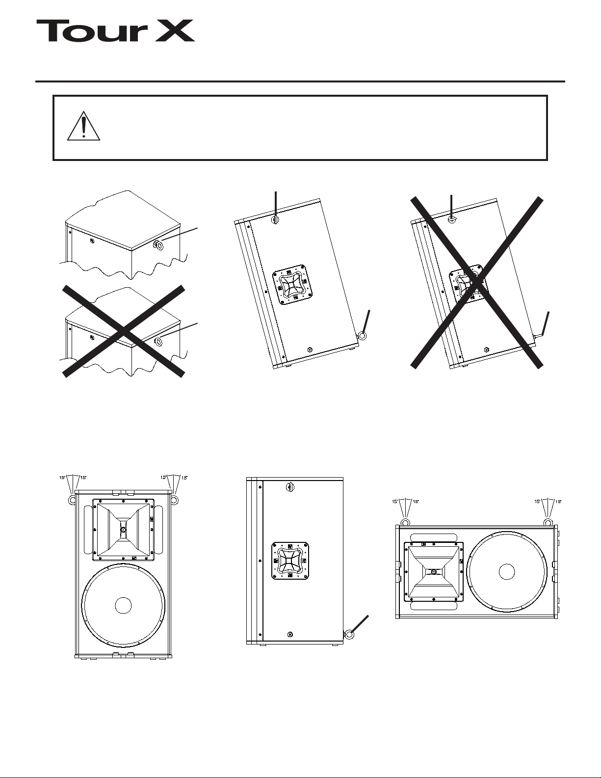
WARNING: Eyebolts must be fully seated and orient in the plane of pull as
shown. Always use fender washers at least 1.5” in diameter and 1/16” thick
under the eyebolt to distribute the load on the enclosure (Figure 3). See
Figures 5-6 on proper ways to suspend a Tour X loudspeaker.
Washer
Used
No
Washer
Used
Figure 3a:
Eyebolt Shown with and
without Washer
50 lbs per
Suspension Point
Figure 3b:
Eyebolts Shown Oriented in the
Plane of Pull (CORRECT)
50 lbs Max Force in any
Direction, Pull-Back Only
Figure 3c:
Eyebolts not Oriented in the Plane
of Pull (INCORRECT)
50 lbs per
Suspension Point
Figure 4a:
Maximum Working Load -
Vertical Orientation
Figure 4b:
Maximum Working Load -
Pull-Back (Rear) Point
Figure 4c:
Maximum Working Load -
Horizontal Orientation
Electro-Voice® Tour X Owner’s Manual5
Page 7
Suspending TX1122, TX1152, and TX2152 (cont’)
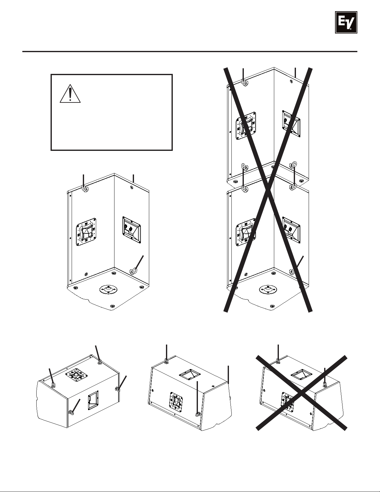
WARNING: Suspension
points are to be used
for a single enclosure
only, never arrays.
Never exceed the limitations
or maximum recommended
working load for the TX1122,
TX1152, and TX2152 systems.
Figure 5a:
Tour X Vertically Suspended
(CORRECT)
Figure 6a:
Tour X Horizontally Suspended
(CORRECT)
Electro-Voice® Tour X Owner’s Manual 6
Tour X Horizontally Suspended
Figure 6b:
(CORRECT)
Tour X Vertically Suspended
Figure 5b:
(INCORRECT)
Figure 6c:
Tour X Horizontally Suspended
(INCORRECT)
Page 8
Rotating the Horn on TX1152 and TX2152
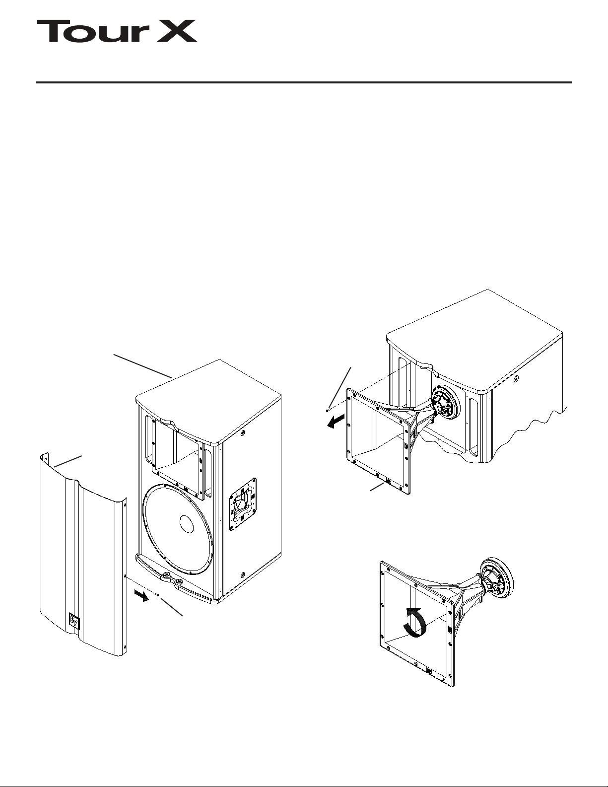
The TX1152 and TX2152 loudspeakers have horns that can be rotated to change the coverage pattern.
The coverage pattern angles are indicated on the horn flange.
1. Remove the (6 or 8) screws that attach the grille to the enclosure (Figure 8).
2. Remove the (12) screws that attach the horn to the enclosure, and disconnect the wires that attach the
compression driver to the input panel (Figure 9).
3. Rotate the horn 90° to the desired vertical coverage pattern (Figure 10).
4. Reconnect the wires that attach the compression driver to the input panel (reverse of Figure 9). The
yellow wire corresponds to the positive terminal, and the yellow and black wire corresponds to the negative terminal. Reattach the horn to the enclosure using the (12) screws.
5. Reattach the grille using the (6 or 8) screws (reverse of Figure 8).
TX1152 or TX2152
Loudspeaker
(TX1152 Shown)
Loudspeaker
Grille
Grille Screw
(x6) or (x8)
Horn Screw
(x12)
Horn/
High-Frequency
Subassembly
Figure 9:
Removing the Horn from
the Enclosure
Figure 8:
Removing the Grille from
the Enclosure
Figure 10:
Rotating the Horn to
Desired Horn Pattern
Electro-Voice® Tour X Owner’s Manual7
Page 9
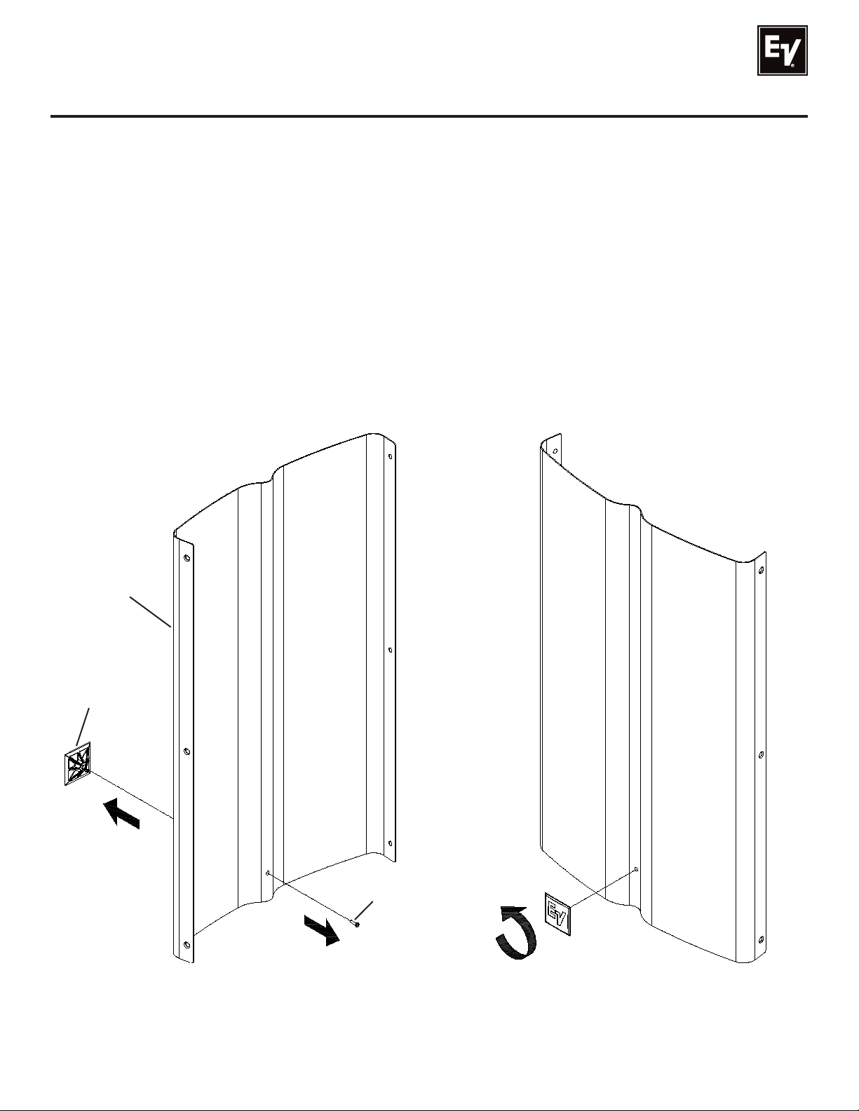
Rotating the Logo
All Tour X loudspeakers have logos that can be rotated (horizontally or vertically) to the user’s desired
orientation. The logo is mounted on a spacer that has the signature “backbone” notch profile of Tour X
grilles.
1. Remove the (6 or 8) screws that attach the grille to the enclosure (Figure 8).
2. Remove the (1) screw on the back of the grille that attaches the spacer to the grille (Figure 11).
3. Rotate the logo and spacer (in increments of 90°) to the desired orientation (Figure 12).
4. Reattach the spacer to the grille using the (1) screw (reverse of Figure 11). Be sure that the screw is
tight enough so as not to rattle during use, but not so tight the logo warps inward.
5. Reattach the grille using the (6 or 8) screws (reverse of Figure 8).
Loudspeaker
Grille
Logo and
Logo Spacer
Logo Spacer
Screw
Figure 11:
Removing the Screw from
the back of the Grille
Electro-Voice® Tour X Owner’s Manual 8
Rotating the Logo and Spacer to
the Desired Orientation
Figure 12:
Page 10
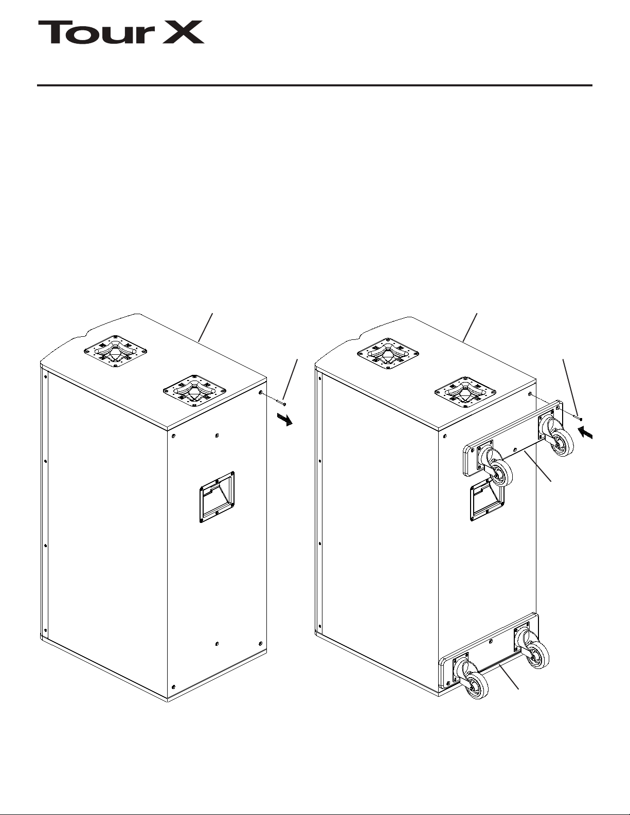
TX-W1 Wheel Kit for TX1181 and TX2181
The TX1181 and TX2181 loudspeakers have (6) mounting points for the TX-W1 Wheel Kit on their rear
panels. The TX-W1 Wheel Kit is made up of (2) skid plates with (2) castors on each skid plate. When
mounted on the rear of a TX1181 or TX2181, they can greatly reduce setup time and virtually eliminate
the need to carry subwoofers.
1. Remove the (6) screws on the rear of the TX1181 or TX2181 loudspeaker (Figure 13).
2. Align the (3) holes at the top of the loudspeaker with the (3) holes of the skid plate. Install (3) screws
back into the rear of the TX1181 or TX2181 loudspeaker. Repeat this step at the bottom of the loudspeaker, ensuring all (6) screws are tight (Figure 14).
TX1181 or TX2181
Loudspeaker
(TX2181 Shown)
Wheel Kit
Mounting
Screw
(x6)
TX1181 or TX2181
Loudspeaker
(TX2181 Shown)
Wheel Kit
Mounting
Screw
(x6)
TX-W1
Wheel Kit
(Top Skid
Plate)
Figure 13:
Removing the (6) Screws from the Rear
of a TX1181 or TX2181 (shown)
TX-W1 Wheel Kit
(Bottom Skid Plate)
Figure 14:
Attaching the TX-W1 and (6) Screws to the
Rear of a TX1181 or TX2181 (shown)
Electro-Voice® Tour X Owner’s Manual9
Page 11
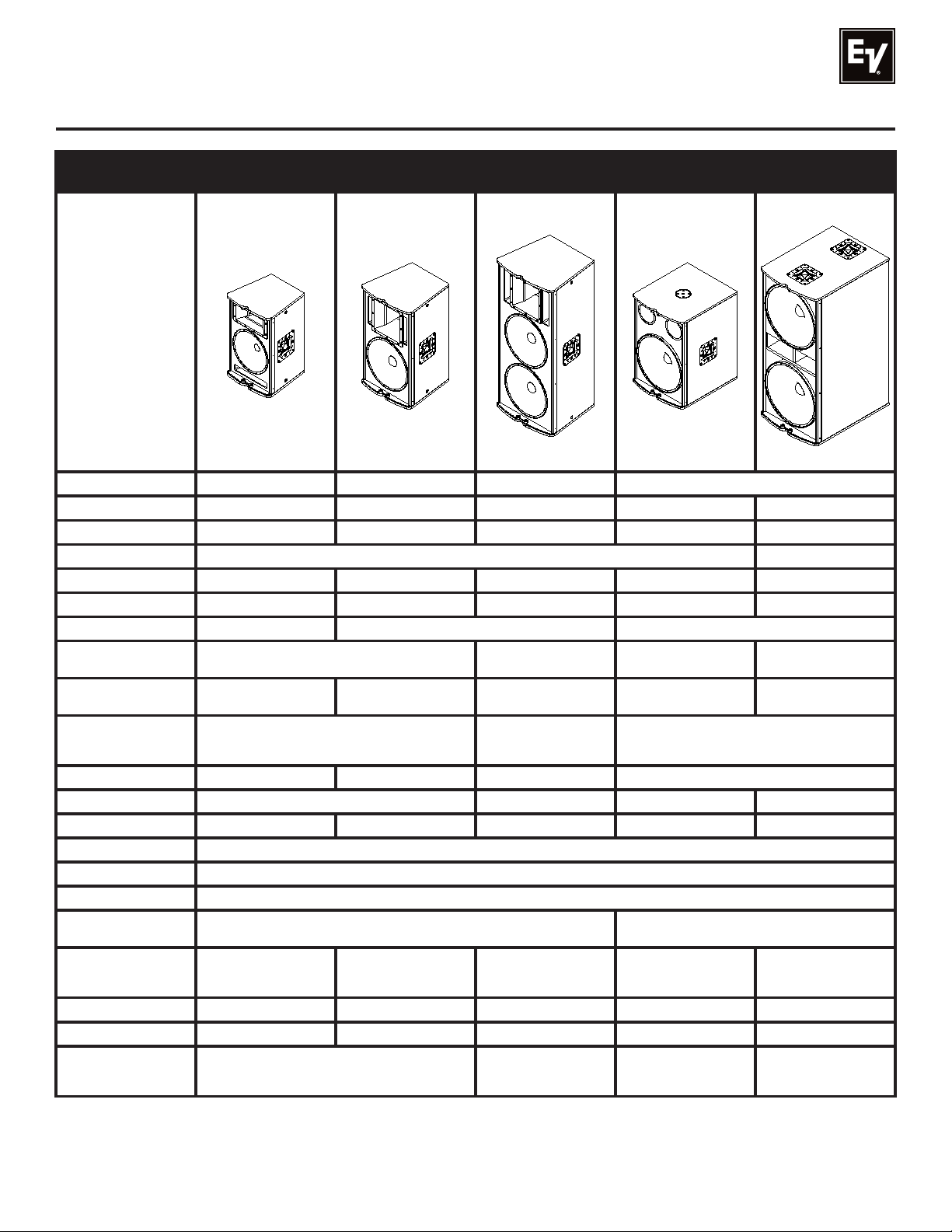
Specifications
Model
(Part Number)
Freq. Response1 (-3 dB): 60 Hz - 20 kHz 55 Hz - 20 kHz 55 Hz - 13 kHz 50 Hz - 160 Hz
Freq. Range1 (-10 dB): 45 Hz - 20 kHz 40 Hz - 20 kHz 50 Hz - 18 kHz 45 Hz - 700 Hz 40 Hz - 1.5 kHz
Rec. Hipass Frequency: 45 Hz 40 Hz 40 Hz 30 Hz N/A
Rec. Low pass Freq.: N/A 80 Hz - 120 Hz
Axial Sensitivity1: 97 dB (1W/1m) 100 dB (1W/1m) 103 dB (1W/1m) 100 dB (1W/1m) 103 dB (1W/1m)
Max. Calculated SPL: 130 dB 133 dB 139 dB 132 dB 138 dB
Coverage (Horiz. x Vert.): 90° x 50° 60° x 40° or 40° x 60° Omnidirectional
Power Handling: 500W Continuous, 2000W Peak
LF Transducer(s):
HF Transducer:
Crossover Frequency: 1750 Hz 1650 Hz 1750 Hz N/A
Nominal Impedance: 8 Ohms 4 Ohms 8 Ohms 4 Ohms
Minimum Impedance: 5.4 Ohms 5.6 Ohms 3.1 Ohms 7.5 Ohms 2.9 Ohms
Connectors: (2) Neutrik Speakon NL4’s
Enclosure Material: Plywood and MDF with EVCoat
Grille: 16GA Steel, Black Powdercoat, with Rotatable Logo
Suspension:
Dimensions (H x W x D):
Net Weight: 44.5 lbs (20.2 kg) 61.2 lbs (27.8 kg) 94.3 lbs (42.8 kg) 74.5 lbs (33.8 kg) 123.5 lbs (56.1 kg)
Shipping Weight: 50.0 lbs (22.7 kg) 68.7 lbs (31.2 kg) 105.8 lbs (48.0 kg) 88.0 lbs (40.0 kg) 139.0 lbs (63.1 kg)
Accessories:
(Part Number)
1
Half Space Measurement.
TX1122
(PRD000138-001)
SMX2120, 12 in
(305mm) Driver
DH3, 1 in (25.4mm) exit
Compression Driver
(6) 3/8” Threaded Points - (2) on each side of Enclosure,
24.3” x 15.0” x 15.0”
(618mm x 382mm x
380mm)
EBK-1 (5542930)
TSP-1 (302053-000)
TSS-1 (302053-001)
TX1152
(PRD000139-001)
SMX2151, 15 in
(381mm) Driver
and (2) on rear of Enclosure
30.6” x 17.5” x 17.5”
(778mm x 446mm x
446mm)
TX2152
(PRD000140-001)
1000W Continuous,
4000W Peak
(2) SMX2151, 15 in
(381mm) Drivers
ND2, 1 in (25.4mm) exit
Neodymium
Compression Driver
45.5” x 20.0” x 18.5”
(1156mm x 508mm x
471mm)
EBK-1 (5542930)
TX1181
(PRD000142-001)
500W Continuous,
2000W Peak
EVS-18S, 18 in
(457mm) Driver
TM
30.3” x 20.0” x 23.3”
(769mm x 508mm x
591mm)
TX-W1 (ACC000043-000)
PCL35 (301397-135)
TX2181
(PRD000143-001)
1000W Continuous,
4000W Peak
(2) EVS-18S, 18 in
(457mm) Drivers
N/A
N/A
45.5” x 20.0” x 27.2”
(1156mm x 508mm x
691mm)
TX-W1 (ACC000043-000)
Electro-Voice® Tour X Owner’s Manual 10
Page 12
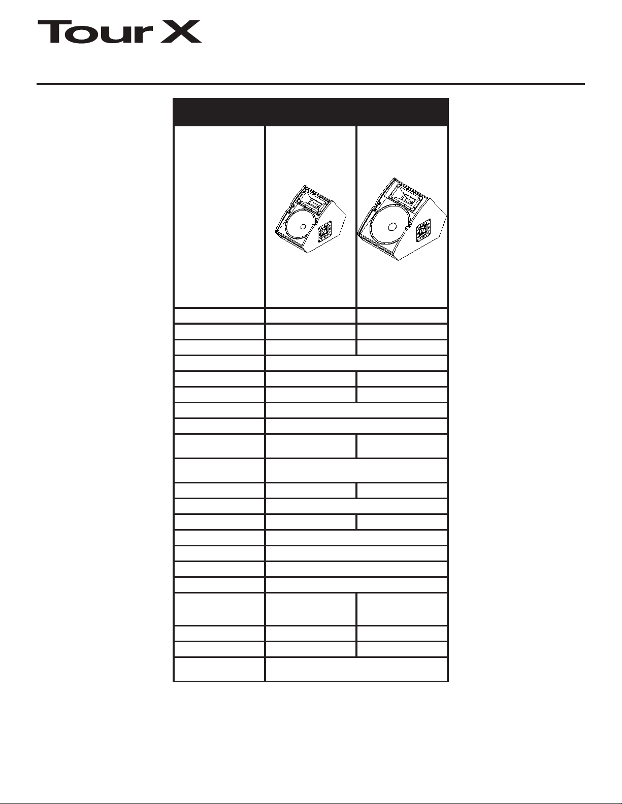
Specifications (cont’)
Model
(Part Number)
Freq. Response1 (-3 dB): 70 Hz - 20 kHz 65 Hz - 20 kHz
Freq. Range1 (-10 dB): 55 Hz - 20 kHz 45 Hz - 20 kHz
Rec. Hipass Frequency: 60 Hz 45 Hz
Rec. Low pass Freq.: N/A
Axial Sensitivity1: 99 dB (1W/1m) 100 dB (1W/1m)
Max. Calculated SPL: 132 dB 133 dB
Coverage (Horiz. x Vert.): 90° x 50°
Power Handling: 500W Continuous, 2000W Peak
LF Transducer(s):
HF Transducer:
Crossover Frequency: 1600 Hz 1750 Hz
Nominal Impedance: 8 Ohms
Minimum Impedance: 6.4 Ohms 6.2 Ohms
Connectors: (2) Neutrik Speakon NL4’s
Enclosure Material: Plywood and MDF with EVCoat
Grille: 16GA Steel, Black Powdercoat, with Rotatable Logo
Suspension: N/A
Dimensions (H x W x D):
Net Weight: 43.7 lbs (19.8 kg) 51.9 lbs (23.5 kg)
Shipping Weight: 49.2 lbs (22.4 kg) 59.4 lbs (27.0 kg)
Accessories:
(Part Number)
TX1122FM
(PRD000144-001)
SMX2121, 12 in
(305mm) Driver
DH3, 1 in (25.4mm) exit
Compression Driver
17.3” x 14.3” x 22.6”
(440mm x 364mm x
573mm)
TX1152FM
(PRD000145-001)
SMX2151, 15 in
(381mm) Driver
TM
18.7” x 17.3” x 25.8”
(475mm x 439mm x
655mm)
N/A
11
1
Half Space Measurement.
Electro-Voice® Tour X Owner’s Manual
Page 13
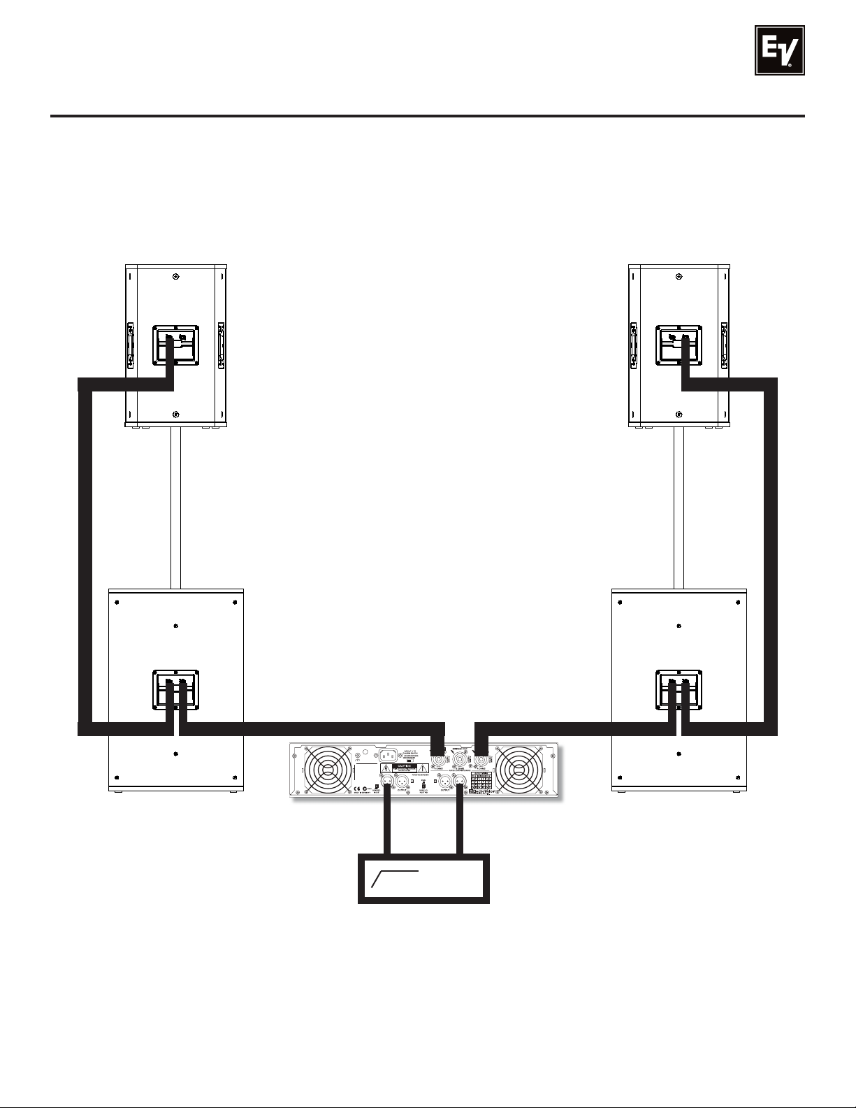
Recommended Configurations
Examples of typical configurations using Tour X series loudspeakers:
TX1122
or TX1152
Loudspeaker
(Sold Separately)
TX1181
Loudspeaker
PCL35
Pole
TX1122
or TX1152
Loudspeaker
PCL35
Pole
(Sold Separately)
TX1181
Loudspeaker
Output A
Input A
Q99
Amplifier
Input B
30 Hz
Output B
From
Mixer
Figure 14a:
(1) TX1122 (or TX1152) and (1) TX1181 per side, paralleled, on (1) Q99 Ampifier
Electro-Voice® Tour X Owner’s Manual 12
Page 14
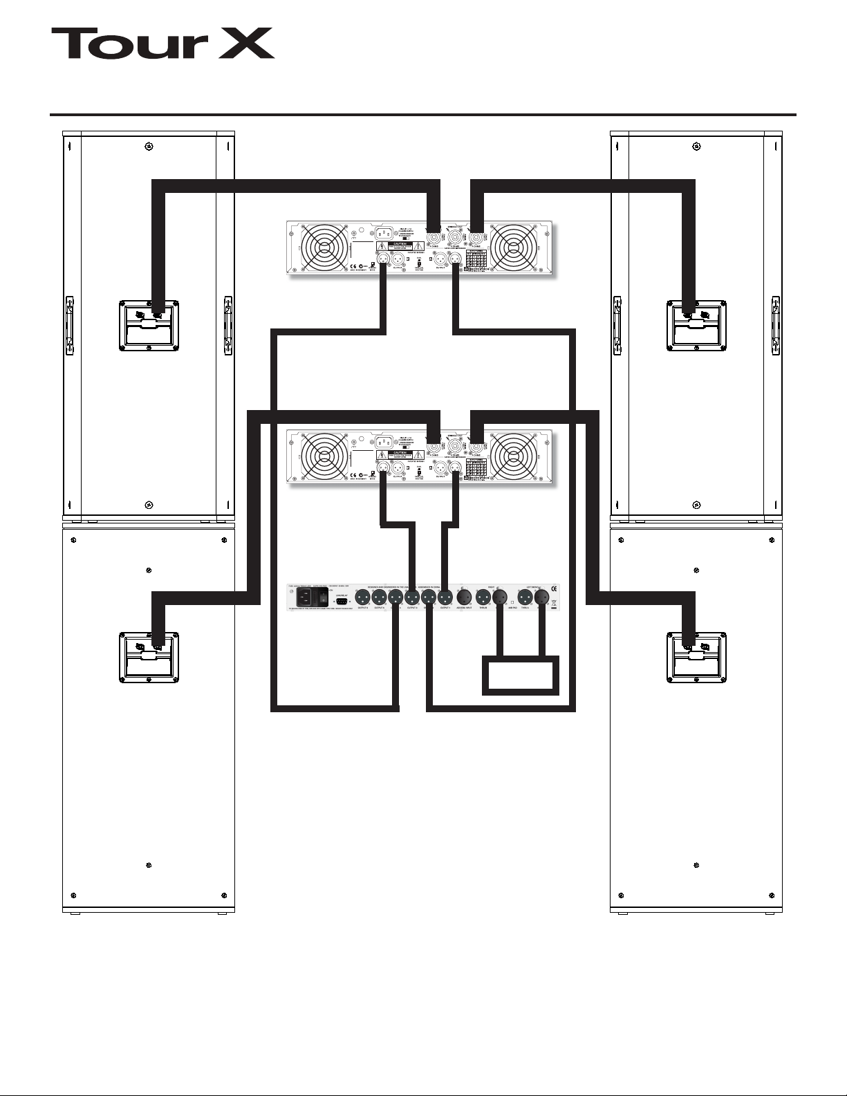
Recommended Configurations (cont’)
TX2152
Loudspeaker
Q1212
Amplifier
Q1212
Amplifier
Input B
Input B
Output 3
Output B
Output B
Output 1
Output A
Input A
Output A
Input A
Input
TX2152
Loudspeaker
A
B
Input
TX2181
Loudspeaker
DC-One
Processor
Output 4
Output 2
From
Mixer
Processor settings are available at
www.electrovoice.com
Figure 14b:
(1) TX2152 and (1) TX2181 per side, on
(2) Q1212 Amplifiers and (1) DC-One Processor
Electro-Voice® Tour X Owner’s Manual13
TX2181
Loudspeaker
Page 15
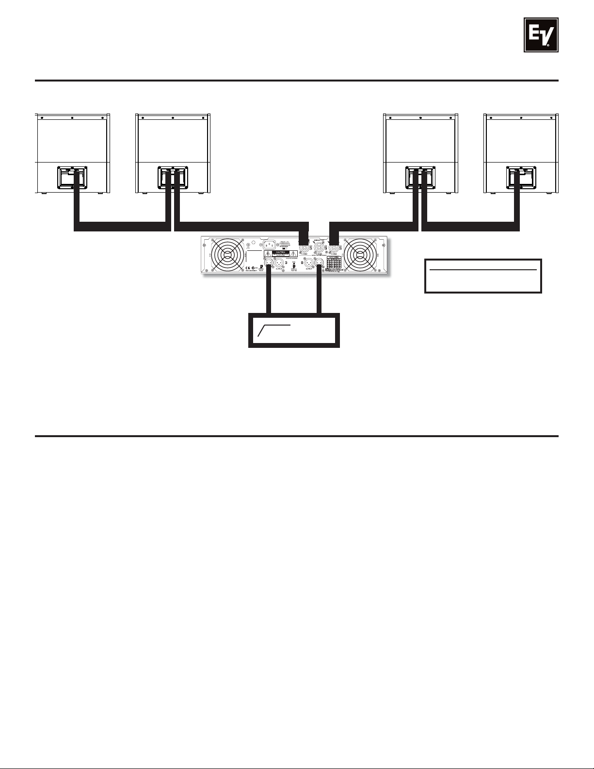
Recommended Configurations (cont’)
TX1122FM
or TX1152FM
Loudspeaker
TX1122FM
or TX1152FM
Loudspeaker
Q99
Amplifier
Input B
60 Hz
Output B
From
Mixer
Output A
Input A
TX1122FM
or TX1152FM
Loudspeaker
Recommended Microphones
Figure 14c:
(4) TX1122FM’s (or TX1152FM’s) paralleled on (1) Q99 Amplifier
TX1122FM
or TX1152FM
Loudspeaker
PL Series
N/Dym Series
Notes
Electro-Voice® Tour X Owner’s Manual 14
Page 16

Electro-Voice
12000 Portland Avenue South, Burnsville, MN 55337
Phone: 952/884-4051, Fax: 952/884-0043
®
www.electrovoice.com
© Bosch Communications Systems 04/2009
Part Number LIT000174 Rev B
U.S.A. and Canada only. For customer orders, contact Customer Service at:
Europe, Africa, and Middle East only. For customer orders, contact Customer Service at:
Other Internatonal locations. For customer orders, Contact Customer Service at:
For warranty repair or service information, contact the Service Repair department at:
Electro-Voice® Tour X Owner’s Manual
For technical assistance, contact Technical Support at: 866/78AUDIO
Specifications subject to change without notice.
800/392-3497 Fax: 800/955-6831
+ 49 9421-706 0 Fax: + 49 9421-706 265
+ 1 952 884-4051 Fax: + 1 952 887-9212
800/685-2606
 Loading...